
Related Manuals for Danfoss VACON NX


Summary of Contents for Danfoss VACON NX
- Page 1 ® vacon ac drives hxl120 cooling unit, ss-piping commissioning and maintenance manual...
-
Page 3: Quick Start- Up Guide
11. Do not energize the main drives before the HX-unit has been running for 30 min without any alarms. Refer to the Chapter 5.4.3, Checklist before starting main NX drives. Vacon Ltd is not responsible for the use of its products contrary to these instructions. Local contacts: http:/ / dr ives.danfoss.com/ danfoss- dr ives/ local - contacts/... - Page 4 The manual contains hyperlinks to web pages. To visit these web pages through the links, you must have access to the Internet and have an Internet browser installed in your computer. Local contacts: http:/ / dr ives.danfoss.com/ danfoss- dr ives/ local - contacts/...
- Page 5 HX control unit The air-cooled NXP 0009 drive that is placed inside the HX-unit for the purpose of controlling and monitoring the primary circuit pump and instruments. Local contacts: http:/ / dr ives.danfoss.com/ danfoss- dr ives/ local - contacts/...
-
Page 6: Table Of Contents
FTSA11 flow switch function ..................31 5.3.6 Temperature set points....................33 5.3.7 Temperature alarm settings ..................38 5.3.8 Low pressure alarm ....................39 5.3.9 Leak switch alarm specifications ................39 Local contacts: http:/ / dr ives.danfoss.com/ danfoss- dr ives/ local - contacts/... - Page 7 Temperature alarms and shutoffs ................52 7.1.3 Low pressure alarm ....................54 7.1.4 Leak alarms ........................ 55 TECHNICAL SPECIFICATION .................... 56 APPENDIX 1..........................58 APPENDIX 2..........................59 APPENDIX 3..........................60 APPENDIX 4..........................61 Local contacts: http:/ / dr ives.danfoss.com/ danfoss- dr ives/ local - contacts/...
-
Page 8: Safety
Risk of damage. Instr uctions on pr eventing possible damage to equipment. WARNING Hot sur face. Instr uctions on pr eventing a possible minor hazar d to per sons or equipment. HOT SURFACE Notification NOTE Local contacts: http:/ / dr ives.danfoss.com/ danfoss- dr ives/ local - contacts/... -
Page 9: General Warnings And Notes When Working With The Hx-Unit
HX-unit frame to the cubicle frame. If the HX-unit is to be without a cubicle, it should be fixed to a floor or wall. Local contacts: http:/ / dr ives.danfoss.com/ danfoss- dr ives/ local - contacts/... - Page 10 REMARQUE Vous pouvez tél échar ger l es ver sions angl aise et fr ançaise des manuel s pr oduit sur l e site http:/ / dr ives.danfoss.com/ knowl edge-center / technical -documentation/ Local contacts: http:/ / dr ives.danfoss.com/ danfoss- dr ives/ local - contacts/...
-
Page 11: Eu Directive
EU DIRECTIVE Manufactur er 's decl ar ation of confor mity ® Below is the Manufacturer's Declarations of Conformity assuring the compliance of VACON drives with the EMC-directives. Local contacts: http:/ / dr ives.danfoss.com/ danfoss- dr ives/ local - contacts/... -
Page 12: Receipt Of Delivery
HX unit type designation code Standar d del iver y var iants HXL-M/V/R-040-N-P/S HXL-M/V/R-120-N-P/S HXM-M/V/R-120-N-P/S HXL-M/R-300-N-S HXM-M/R-300-N-S Connections HX-Module; Threads or flanges, HXL300 and HXM300 flanges only VEDA/Rittal; Flanges Local contacts: http:/ / dr ives.danfoss.com/ danfoss- dr ives/ local - contacts/... -
Page 13: Introduction
Chapter 7 TROUBLESHOOTING includes fault tracing to help the user identify and solve a problem ® when the HX control unit (air-cooled VACON NXP 0009) has an active alarm or fault. Chapter 8 TECHNICAL SPECIFICATION Local contacts: http:/ / dr ives.danfoss.com/ danfoss- dr ives/ local - contacts/... -
Page 14: Process And Instrumentation
HX-unit floor, all instruments are placed in the primary circuit. Therefore the temperature and flow monitoring in the secondary circuit is the responsibility of the customer and/or end-user. Local contacts: http:/ / dr ives.danfoss.com/ danfoss- dr ives/ local - contacts/... -
Page 15: Primary Circuit Components And Function
Keeping the temperature as high as possible in the primary circuit, with regards to the type and load of the main drive, lowers the risk of condensation inside the drive cubicle. Figure 4.2-4 Local contacts: http:/ / dr ives.danfoss.com/ danfoss- dr ives/ local - contacts/... -
Page 16: Control Unit
It can also be used to get a pressure reference value if the pressure transmitter is thought to be malfunctioning. Local contacts: http:/ / dr ives.danfoss.com/ danfoss- dr ives/ local - contacts/... -
Page 17: Control / Supervision Parameters
If the flow for some reason is shut down in the secondary circuit, the HX-unit will main drive load, due to a high-temperature shutoff. NOTE Local contacts: http:/ / dr ives.danfoss.com/ danfoss- dr ives/ local - contacts/... -
Page 18: Hx-Unit Electrical Box
AISI pipes, PTFE and Tesnit BA-S seals. When adding liquid to the primary circuit it is recommended that a filter be used so that no particles larger than 0.3 mm can enter the primary circuit. Local contacts: http:/ / dr ives.danfoss.com/ danfoss- dr ives/ local - contacts/... - Page 19 HX-unit e.g. high amounts of chloride, chlorine, oil etc. The HX-unit with the PVC-C pipes uses EPDM rubber seals that will deteriorate if they come in contact with oil. Local contacts: http:/ / dr ives.danfoss.com/ danfoss- dr ives/ local - contacts/...
-
Page 20: Required Ambient Conditions
Metal to metal waste Electrical equipment to electrical waste Glycol and corrosion inhibitors: Check national or local ecological directives for information on how to dispose of the drained liquid. Local contacts: http:/ / dr ives.danfoss.com/ danfoss- dr ives/ local - contacts/... -
Page 21: Commissioning
If required, e.g. by national regulations or generally acknowledged safety standards, additional protection must be added to the unit, e.g. warning signs or additional protective gear. Figure 5.1-3 Local contacts: http:/ / dr ives.danfoss.com/ danfoss- dr ives/ local - contacts/... -
Page 22: Pipe Connections
If the welding has been done by other means the pipes have to be thoroughly flushed with water at a minimum of 3 m/s for 5 minutes. Local contacts: http:/ / dr ives.danfoss.com/ danfoss- dr ives/ local - contacts/... -
Page 23: Pressure Test
The pressure in the primary circuit can be monitored from the pressure indicator PI11 during the pressure test. If the pressure remains constant for 15 minutes, the system is airtight. If the pressure Local contacts: http:/ / dr ives.danfoss.com/ danfoss- dr ives/ local - contacts/... -
Page 24: Setting Up The Primary Circuit
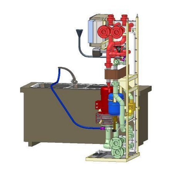
If corrosion inhibitors are used they can be mixed, in the right amount, with the water in the barrel. • Depending on the system size there has to be 20-200 litres of liquid in the barrel. Figure 5.1-11 Local contacts: http:/ / dr ives.danfoss.com/ danfoss- dr ives/ local - contacts/... -
Page 25: Adding Liquid And De-Airing
V161 filling valve is closed again. 7. Close the valve V310 first, and then the valve V311. This procedure will leave the specific drive section filled with water. Local contacts: http:/ / dr ives.danfoss.com/ danfoss- dr ives/ local - contacts/... - Page 26 The pre-pressure in the primary circuit should be set to 1.5 bar. During operation the pre-pressure should be between 1.0 to 1.5 bar. If the pre-pressure is reduced to below 1.0 bar during operation -pressure is below 0.5 bar. Local contacts: http:/ / dr ives.danfoss.com/ danfoss- dr ives/ local - contacts/...
-
Page 27: Adding Corrosion Inhibitor When Using A Fresh Water System
+70°C. There are two alternatives to bring the supply cables to HX- unit: from under or from above (Figure 5.2-1, Figure 5.2-2). Figure 5.2-1 Figure 5.2-2 Local contacts: http:/ / dr ives.danfoss.com/ danfoss- dr ives/ local - contacts/... -
Page 28: Signal Cables
The control unit also includes a Fieldbus uplink card (Profibus). The customer can use this uplink to ® get any of the VACON uplink the customer can monitor the HX-unit from an external interface at a chosen location. More Local contacts: http:/ / dr ives.danfoss.com/ danfoss- dr ives/ local - contacts/... -
Page 29: Application Parameter List
Fieldbus outlet 4 1511 P2.11.5 Fieldbus outlet 5 P2.11.6 Fieldbus outlet 6 P2.11.7 Fieldbus outlet 7 P2.11.8 Fieldbus outlet 7 P3.5 *) FV11 reference temperature Table 5.3-1, Parameter list Local contacts: http:/ / dr ives.danfoss.com/ danfoss- dr ives/ local - contacts/... -
Page 30: Parameter Description
This is useful for testing and commissioning purposes because all shutoffs are also deactivated during these 30 seconds. The value, 169, will deactivate the attempt to change the pump and should be used when operating the HXL040 or HXL120. Local contacts: http:/ / dr ives.danfoss.com/ danfoss- dr ives/ local - contacts/... -
Page 31: General Information About Alarms And Shutoff Limits
Adjusting the FTSA11 flow switch: 1. Turn the pump power switch (the black and white switch in Figure 4.2-7) connect the power to the HX-unit. This will activate the FTSA11. Local contacts: http:/ / dr ives.danfoss.com/ danfoss- dr ives/ local - contacts/... - Page 32 1 "3" 3 actual switching switching output switching point point "1" 2 3 1 "2" 3 1 2 "3" Star t "S0" "SP" "123" Figure 5.3-2 FTSA11 parameter hierarchy Local contacts: http:/ / dr ives.danfoss.com/ danfoss- dr ives/ local - contacts/...
-
Page 33: Temperature Set Points
The primary circuit temperature is individual for every project. Here are three examples that show how the primary circuit temperature is calculated depending on which of the three above-mentioned factors is the deciding one: Local contacts: http:/ / dr ives.danfoss.com/ danfoss- dr ives/ local - contacts/... - Page 34 Ambient temperature = 40C Maximum relative humidity = 80% Acc. to chart 3.3-1Dew point is @ 36C Local contacts: http:/ / dr ives.danfoss.com/ danfoss- dr ives/ local - contacts/...
- Page 35 RH from 80% to 50%, by using a humidity remover, will allow the primary circuit temperature to be set to 30C therefore allowing the main drives to be run at full load. Local contacts: http:/ / dr ives.danfoss.com/ danfoss- dr ives/ local - contacts/...
- Page 36 Ambient temperature = 30C Maximum relative humidity = 95% Because the ambient temperature is beneath the primary circuit temperature there is no risk of condensation in the main drive. Local contacts: http:/ / dr ives.danfoss.com/ danfoss- dr ives/ local - contacts/...
- Page 37 40C that would make a scenario with an ambient temperature over 40C impossible. In a case like this it is Local contacts: http:/ / dr ives.danfoss.com/ danfoss- dr ives/ local - contacts/...
-
Page 38: Temperature Alarm Settings
The HX-unit over temperature fault is designed to work as protection in case of a sudden change in the primary circuit for example if the flow in the secondary circuit for some reason is stopped. Local contacts: http:/ / dr ives.danfoss.com/ danfoss- dr ives/ local - contacts/... -
Page 39: Low Pressure Alarm
The leak sensor generates an alarm if there is liquid on the floor plate inside the HX-unit due to a leak in the unit. If there is condensation inside the HX-unit, the leak switch can Local contacts: http:/ / dr ives.danfoss.com/ danfoss- dr ives/ local - contacts/... -
Page 40: Step 4, Adjusting The Flow
9. Wait for 5 min. and open the manual de-airing valve V162 to let out any air that might have been stuck in the pump housing. 10. Add water to get the pressure back up to 1.5 bars. Then start the pump again and leave it running. Local contacts: http:/ / dr ives.danfoss.com/ danfoss- dr ives/ local - contacts/... -
Page 41: Adjusting The System Flow And Setting The Switch Point Of The Ftsa11
3. Adjust the frequency of the pump to match the required total nominal flow + 10% (see example). Exampl e: If you are using 3 x Ch74 drive, the nominal flow according to the NX Liquid drive manual Local contacts: http:/ / dr ives.danfoss.com/ danfoss- dr ives/ local - contacts/... - Page 42 5 seconds, the control unit application filters out the alarm. If the alarm is still active -unit pump and the drives shut down. HX_-120, pure water, B=1 70,0 60,0 50,0 40,0 30,0 20,0 10,0 Flow [L/min} Diagram 5.4-1 Pure water, B = 1 Local contacts: http:/ / dr ives.danfoss.com/ danfoss- dr ives/ local - contacts/...
- Page 43 Diagram 5.4-2 20% glycol/ 80% water, B = 1.35 HX_-120, 40% glycol, B=1,82 40,0 35,0 30,0 25,0 20,0 15,0 10,0 Flow [L/min} Diagram 5.4-3 40% glycol / 60% water, B = 1.82 Local contacts: http:/ / dr ives.danfoss.com/ danfoss- dr ives/ local - contacts/...
-
Page 44: Checklist Before Starting Main Nx Drives
The load of the drives should also be increased step by step, otherwise the temperature might change too fast and cause an alarm, or in the worst case, a drive malfunction. Before starting the drives: Local contacts: http:/ / dr ives.danfoss.com/ danfoss- dr ives/ local - contacts/... - Page 45 Troubleshooting information and unit service information is located in the last two chapters of this manual. For further information contact your local distributor. Local contacts: http:/ / dr ives.danfoss.com/ danfoss- dr ives/ local - contacts/...
-
Page 46: Unit Maintenance
HX control box can used to re-route the alarms to a place where they are monitored at all times. e Fieldbus interface then the indicators on the HX electrical box must be moved to a position where they can be monitored at all times. Local contacts: http:/ / dr ives.danfoss.com/ danfoss- dr ives/ local - contacts/... -
Page 47: Maintenance By Component
® 3. Take the main drives connected to the HX-unit offline, according to the VACON NX Liquid 4. Shut down the power to the HX- 4.2-7. Local contacts: http:/ / dr ives.danfoss.com/ danfoss- dr ives/ local - contacts/... -
Page 48: Heat Exchanger
If the flow in the secondary circuit is too low, there may be some biological residue clogging the heat exchanger. Local contacts: http:/ / dr ives.danfoss.com/ danfoss- dr ives/ local - contacts/... - Page 49 HX-unit. 5. Connect the clean unit in reverse order using the instructions above. Add liquid and de-air the unit according to the instructions in chapter 5.1.6 and 5.1.7. Local contacts: http:/ / dr ives.danfoss.com/ danfoss- dr ives/ local - contacts/...
-
Page 50: Pressure Vessel
V161, otherwise the air in the filling hose will enter the unit during filling. 10. Due to the small amount of liquid removed during this process it is not necessary to add any corrosion inhibitor. Local contacts: http:/ / dr ives.danfoss.com/ danfoss- dr ives/ local - contacts/... -
Page 51: Troubleshooting
FTSA11 (refer to chapter 5.4.2 stage). Adjusting the system flow and setting commissioning. the switch point of the FTSA11). Table 7.1-1, Flow fault detection Local contacts: http:/ / dr ives.danfoss.com/ danfoss- dr ives/ local - contacts/... -
Page 52: Temperature Alarms And Shutoffs
The FTSA11 setup values Check the project parameters (refer have been wrongly Table 5.3-1, Parameter list) and adjusted during compare with actual commissioning. temperature. Table 7.1-2 High temperature fault detection Local contacts: http:/ / dr ives.danfoss.com/ danfoss- dr ives/ local - contacts/... - Page 53 FTSA11. To get an accurate value the portable temperature gauge must be connected close to the FTSA11. Replace the FTSA11 if necessary. Table 7.1-3, Low temperature fault detection Local contacts: http:/ / dr ives.danfoss.com/ danfoss- dr ives/ local - contacts/...
-
Page 54: Low Pressure Alarm
Compare the value from the pressure gauge, PI11, with the value from the pressure transmitter PT11. pressure transmitter is broken it has to be replaced. Table 7.1-4, Pressure fault detection Local contacts: http:/ / dr ives.danfoss.com/ danfoss- dr ives/ local - contacts/... -
Page 55: Leak Alarms
If the yellow light is still on then the sensor is most likely broken and will need to be replaced. Figure 7.1-5, Leak fault detection Local contacts: http:/ / dr ives.danfoss.com/ danfoss- dr ives/ local - contacts/... -
Page 56: Technical Specification
• 180 kg, PVC-C (+165kg for Rittal cubicle and +190 kg for VEDA cubicle) • 250 kg, AISI304 (+165kg for Rittal cubicle and +190 kg for VEDA cubicle) Local contacts: http:/ / dr ives.danfoss.com/ danfoss- dr ives/ local - contacts/... - Page 57 The pressure before 3- or 2-way valve must be at least 2 bar to prevent cavitations. See cavitations diagram in Components Specifications and Maintenance Instructions n:o 2 , TAC Venta, page 2. Local contacts: http:/ / dr ives.danfoss.com/ danfoss- dr ives/ local - contacts/...
- Page 58 0.46 bar 0.58 bar 90 l/min 90 l/min 0.03 bar 0.46 bar 0.49 bar 180 l/min 0.46 bar 0.46bar => Pressure drop varies between 0.46 bar – 0.58 bar Local contacts: http:/ / dr ives.danfoss.com/ danfoss- dr ives/ local - contacts/...
- Page 59 0.16 bar 90 l/min 90 l/min 0.03 bar 0.04 bar 0.07 bar 180 l/min 0.04 bar 0.04 bar => Pressure drop varies between 0.04 bar – 0.20 bar Local contacts: http:/ / dr ives.danfoss.com/ danfoss- dr ives/ local - contacts/...
- Page 60 Never use force when installing plastic fittings. It is especially important that the pipe installation is low stress. Local contacts: http:/ / dr ives.danfoss.com/ danfoss- dr ives/ local - contacts/...
- Page 61 4 x M12 4 x M16 4 x M16 4 x M16 4 x M16 8 x M16 Thread connections: Steel threads tighten by pipe wrench or other suitable tool. Local contacts: http:/ / dr ives.danfoss.com/ danfoss- dr ives/ local - contacts/...
- Page 62 Document ID: Vacon Ltd DPD01506B Member of the Danfoss Group Rev. B Runsorintie 7 65380 Vaasa Sales code: DOC-INSNXHXL120+DLUK Finland...
Need help?
Do you have a question about the VACON NX and is the answer not in the manual?
Questions and answers