Sign In
Upload
Manuals
Brands
Danfoss Manuals
Controller
176F7307
Danfoss 176F7307 Manuals
Manuals and User Guides for Danfoss 176F7307. We have
1
Danfoss 176F7307 manual available for free PDF download: Manual
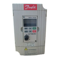
Danfoss 176F7307 Manual (91 pages)
VLT MICRO
Brand:
Danfoss
| Category:
Controller
| Size: 0.82 MB
Table of Contents
Table of Contents
1
Getting Started
3
Chapter 1 Introduction
3
Description of Serial Number
4
Nameplate Information
4
Receiving, Inspection, and Storage
4
Receiving, Transporting, Inspecting, and Storage
4
General Technical Data
5
Specifications
8
External Parts and Labels
9
Installation Requirements
10
Chapter 2 Installation and Wiring
10
Wiring
11
200-240 VAC Units
12
Main Circuit Standard Wiring Chart
12
Control Terminal Designations (Factory Settings)
13
Installation Notes
14
Safety Precautions
14
Description of the Digital Keypad/Display
16
Operating Modes and Functions
16
Chapter 3 Digital Keypad/Display Operation
16
Explanation of the LED Indicators
17
Function / Program
17
Electrical Installation, Power
18
Motor Start
18
Programming
18
Quick Set-Up
18
Explanation of Displayed Messages
19
Operating the Digital Control Panel
20
Operation
21
Description of Parameters
22
Pin Header/Jumper Diagrams
22
Pr.00 Master Frequency Source Select
22
Chapter 4 Description of Parameters
22
Pr.01 Operation Command Source Select
23
Pr.02 Motor Stop Method Select
23
Pr.03 Maximum Output Frequency
24
Pr.04 Motor Frequency
24
Pr.05 Motor Voltage
24
Pr.06 MID-Point Frequency
24
Pr.08 Minimum Output Frequency
25
Pr.09 Minimum Output Voltage
25
Custom V/F Curve
25
Fan/Pump V/F Curve
25
Commonly Used V/F Pattern Settings
26
General Purpose
26
Fans and Pumps
26
High Starting Torqu
26
Pr.11 Deceleration Time
27
Pr.12 Acceleration Time
27
Pr.13 Deceleration Time
28
Pr.14 S-Curve
28
Pr.15 Jog Accel. / Decel. Time
29
Pr.16 Jog Frequency
29
Pr.24 Reverse Run Inhibit
30
Pr.25 Over-Voltage Stall Prevention
30
Pr.26, Pr.27 Over-Current Stall Prevention
30
Pr.26 Over-Current Stall Prevention During Acceleration
30
Pr.27 Over-Current Stall Prevention During Operation
31
Pr.28 DC Braking Current
31
Pr.29 DC Braking Time During Start-Up
32
Pr.30 DC Braking Time During Stopping
32
Pr.31 DC Braking Start-Up Frequency
32
Pr.32 Momentary Power Loss Operation Mode Selection
32
Pr.33 Maximum Allowable Power Loss Time
33
Pr.34 Minimum Base Block Time
33
Pr.35 Speed Search Deactivation Current Level
33
Pr.36 Reference Frequency Upper Limit
34
Pr.37 Reference Frequency Lower Limit
34
Pr.38 Multi-Function Input Terminals (M0, M1)
34
Pr.39 Multi-Function Input Terminals (M2)
34
Pr.40 Multi-Function Input Terminals (M3)
35
Pr.41 Multi-Function Input Terminals (M4)
35
Pr.42 Multi-Function Input Terminals (M5)
35
Parameter - Function List
35
D05: External Reset
37
D06, 07, 08: Multi-Step Speed Command
37
D09: Jog Frequency Control
38
D10: Accel./Decel. Speed Inhibit
38
D11: First or Second Accel./Decel. Time Select
38
D12, D13: External Base Block
39
D14, D15: Increase/Decrease Output Frequency Control
40
D16, D17: PLC Function Control
40
D18: Counter Trigger
41
D19: Counter Reset
41
Pr.43 Analog Output to Drive External Meter
42
Pr.44 Analog Output Gain
42
Pr.45 Multi-Function PHC Output Terminal (MO1)
43
Pr.46 Multi-Function Output Relay Contact RA-RC (NO), RB-RC (NC)
43
Multi-Function Output Program Values
43
Multi-Function Terminals Wiring Example
44
Pr.47 Desired Frequency Attained
44
Multi-Function Output Terminal Operation (D01 and D08)
45
Pr.48 Output Frequency Offset
45
Pr.49 Process Signal Bias
45
Pr.50 Process Signal Gain
45
Pr.52, Pr.53 – Motor Operating Specifications
48
Pr.52 Motor Rated Current
48
Pr.53 Motor No-Load Current
49
Pr.54 Torque Compensations
49
Pr.55 Slip Compensation
49
Pr.56 Special Output Display
49
Pr.58, Pr.59 – Electronic Thermal Overload Relay
50
Pr.58 De-Rating for Output Current Vs. Temperature
50
Pr.60, Pr.61, Pr.62 – Over-Torque Detection
51
Pr.60 Over-Torque Detection Mode
51
Pr.61 Over-Torque Detection Level
51
Pr.62 Over-Torque Detection Time
51
Pr.64 User Defined Function for Display
52
Pr.65 Coefficient of Line Speed
52
Pr.66 Master Frequency
52
Pr.67, Pr.68, Pr.69 Frequency Setting Prohibited
52
Pr.70 Frequency Bandwidth Setting Prevention
53
Pr.71 PWM Carrier Frequency Select
53
Pr.72 Auto-Reset / Restart Operation Following a Fault
54
Pr.73, 74, 75 the 1St, 2Nd, 3Rd most Recent Fault Record
54
Pr.76 Parameter Key
55
Pr.77 Reserved
55
Pr.78 PLC (Programmable Logic Controller) Operation Mode
55
Example 1 (Pr.78 = D01): Execute One Cycle through the PLC Program
56
Example 2 (Pr.78 = D02): Continuously Execute Program Cycles
56
Example 3 (Pr.78 = D03): Execute One Cycle Step by Step
57
Pr.79 PLC Forward/Reverse
58
Pr.80 Manufacturer Model Information
60
Pr.81 ~ Pr.87 PLC Program Step Time Intervals
60
Pr.95 Auto Energy-Saving
60
Output Characteristics Curve of Energy-Saving Operation
60
Pr.96 Count down Completion Settings
61
Pr.97 Preset Count down Completion Settings
61
Pr.100 Software Version
61
Pr.101 Auto Acceleration/Deceleration Adjustment Selection
62
Pr.102 Auto Voltage Regulation (AVR)
62
Pr.111 Deceleration S Curve Setting
63
Pr.112 External Terminal Scanning Time
63
Chapter 5 Summary of Parameters
64
Chapter 6 Troubleshooting and Fault Information
71
The Over-Current Hardware
72
The AC Drive Temperature
72
Internal Electronic Overload
73
Motor Overload
73
Over-Current During Acceleration
73
Over-Current During Deceleration
73
AC Motor Drive Internal
74
AC Motor Drive E2PROM
74
Ground Fault or Fuse Failure
74
External Baseblock
74
Dimensions 200-240V Series
75
Appendix A Dimensions
75
Dimensions 200-240V CE Series
76
Brake Resistors
77
Remote Keypad Kit
77
Appendix B Accessories
77
DIN Rail Adaptor Bracket Kit
78
Appendix C CE Labeling
79
Pr.88 Communication Address
84
Pr.89 Transmission Speed
84
Pr.90 Transmission Fault Treatment
84
Appendix D Serial Communication
84
Computer Control
85
Data Format
85
Communication Protocol
87
Communication Data Frame
87
ASCII Mode
87
Adr
88
CMD
88
AC Drive Responding Mode
89
Data Characters
89
Chk
89
AC Drive Communication Error
90
Advertisement
Advertisement
Related Products
Danfoss 176F7300
Danfoss 176F7302
Danfoss 176F7303
Danfoss 176F7304
Danfoss 176F7305
Danfoss 176F7301
Danfoss 176F7306
Danfoss 176F7308
Danfoss 11156465
Danfoss 100B1601
Danfoss Categories
Controller
DC Drives
Thermostat
Control Unit
Water Pump
More Danfoss Manuals
Login
Sign In
OR
Sign in with Facebook
Sign in with Google
Upload manual
Upload from disk
Upload from URL