Advertisement
Quick Links
SSV WORKS, 201 N. Rice Ave Unit A, Oxnard, CA 93030
www.SSVworks.com
|
Phone: 818-991-1778
3
pg
Panels and Dash
Disassembly
5
pg
Amp Tray
Installation
7
pg
JVC MR1
Installation
10
pg
Subwoofer
Installation
12
pg
Door Panel Speakers
Installation
|
Fax: 866-293-6751
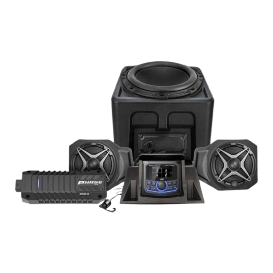
Ranger XP1000
RG4-Q3A1
2018-Up Polaris Ranger XP1000
3 Speaker Audio Kit
Phase 3 with JVC MR1
Advertisement

Subscribe to Our Youtube Channel
Related Manuals for SSV Works RG4-Q3A1


Summary of Contents for SSV Works RG4-Q3A1
- Page 1 RG4-Q3A1 2018-Up Polaris Ranger XP1000 3 Speaker Audio Kit SSV WORKS, 201 N. Rice Ave Unit A, Oxnard, CA 93030 Phase 3 with JVC MR1 www.SSVworks.com Phone: 818-991-1778 Fax: 866-293-6751 Ranger XP1000 Panels and Dash Disassembly Amp Tray Installation JVC MR1...
- Page 2 WIRING DIAGRAM OF COMPLETE KIT Figure 1 Figure 1 is designed to show the installer a reference overview of the complete 3 speaker wiring diagram. Each installation section will have its own detailed wiring diagram. Description Part # Bluetooth Media Receiver w/ 2.7” color display B-MR1 JVC to SSV Harness Adapter, 3 ft.
-
Page 3: Tools Needed For Installation
All SSV Works enclosures are covered by a limited lifetime warranty against defects in material or workmanship. instructions completely before All SSV Works Electronics are covered by a limited 1 year warranty against defects in material or workmanship. installation to avoid possible injury, or All Kicker Speakers are covered by a limited 1 year warranty against defects in material or workmanship. - Page 4 G. Extract push pins exposed from cup holder removal. H. Extract push pins exposed from gauge cluster removal. I. Extract push pins located above driver and passenger side cup J. Lift to remove the dash. holders. K. Extract push pins located beneath 12v sockets. L.
- Page 5 WARRANTY INFORMATION: Please read and understand these All SSV Works enclosures are covered by a limited lifetime warranty against defects in material or instructions completely before workmanship. All SSV Works Electronics are covered by a limited 1 year warranty against defects installation to avoid possible injury, or in material or workmanship.
- Page 6 A. Unscrew the two (2) torx screws connecting the dash bracket at the rear B. Move the factory wiring to the rear of the dash cavity. Place the of the dash cavity. Remove the under dash bracket. RG4 Amp mounting plate in the former location of the factory NOTE: IT WILL NOT BE RE-INSTALLED.
-
Page 7: Installation Notes
DASH KIT ASSEMBLY PARTS LIST PARTS LIST IMAGES 3. M6 x 1.0 Screws 4. U-Clips x2 5. Push Pins x2 1. DMR1 Dash Kit x1 2. JVC MR1 Headunit and x2 (T-30 torx) Trim Ring JVC MR1 Media Player, base mounting plate, trim ring and dash screws included with kit compatible head INSTALLATION NOTES units not included with RG4-DMR1. - Page 8 C. Using a panel removal tool gently lift the existing plastic panel on the center dash support. Install the two (2) supplied U-Nut clips by sliding them onto the bottom of the center dash panel support and align holes as needed. E.
- Page 9 J. Secure the backside of the R1 with (2) push pins (circled in blue). I. Secure the MR1 with the (4) M3.5 screws provided with the MR1. Fasten (2) M6 T30 screws and washers into each front hole (circled in pink). K.
- Page 10 SUBWOOFER ENCLOSURE PARTS LIST PARTS LIST IMAGES 1. RG4-US10 Enclosures 2. Enclosure Bracket A 2. Enclosure Bracket B 4. M6 Flathead 4mm 5. M6 Allen Torx 5. Foam Circles Hex Screws x4 Screws x2 NOTE: To avoid subwoofer damage, do not face the subwoofer down or rest the enclosure on the subwoofer when installing bracket to the bottom of the enclosure.
- Page 11 E. Place SSV bracket B over the factory screw holes and refasten F. With the bracket secured to the floorboard, place the enclosure in front of down with the (3) factory T40 torx screws removed in the the floorboard bracket. To allow proper engagement, tilt the enclosure back previous step.
- Page 12 SUBWOOFER WIRING DIAGRAM Description Part # Detail Description 800.5 Amplifier 32-Pin Universal Harness B-H2605 Connect Subwoofer Output from B-H2605 to B-H2702 2-Pin Audio, Sub Extension Harness B-H2702 Connect B-H2702 directly to the Subwoofer FRONT KICK PODS PARTS LIST PARTS LIST IMAGES 1.
- Page 13 C. Remove factory T25 torx screws located underneath the dash. D. Located on the inside top of the pocket you will have two holes, route speaker wire though the larger hole. The smaller hole will be used to mount the pod in Step P. E.
- Page 14 FRONT KICK PODS WIRING DIAGRAM Description Part # Front Speaker Harness (48”) B-H1909 Detail Description Connect Front Output from B-H2605 to B-H1909 Connect Speaker Pods connectors to B-H2935 CONNECTING POWER & GROUND CABLE TO BATTERY Battery Terminal Cable Power Wire Break Break off tab...
-
Page 15: Amp Wiring Diagram
Connect Rock & Ride rocker switch to “Ext. Switch” Install fuseholder between B-H1587 & battery terminal cable. Connect ground ring terminal to chassis ground. THIS CONCLUDES THE INSTALLATION PROCESS. REPLACE THE FACTORY PANELS AND SEATS. QUESTIONS? PLEASE CONTACT SSV WORKS AT 818-991-1778 OR EMAIL SUPPORT@SSVWORKS.COM... - Page 16 © 2023 SSV Works, Oxnard, CA 93030 RG4-Q3A3 8-15-23...
Need help?
Do you have a question about the RG4-Q3A1 and is the answer not in the manual?
Questions and answers