Advertisement
Quick Links
SSV WORKS, 201 N. Rice Ave Unit A, Oxnard, CA 93030
www.SSVworks.com | Phone: 818-991-1778 | Fax: 866-293-6751
WARRANTY INFORMATION:
All SSV Works enclosures are covered by a limited lifetime warranty against defects in
material or workmanship. All SSV Works Electronics are covered by a limited 1 year warranty
against defects in material or workmanship. All SSV Works Speakers are covered by a
limited 1 year warranty against defects in material or workmanship. Labor for replacement of
defective components is not covered. Contact SSV Works for further warranty information.
TOOLS NEEDED FOR INSTALLATION
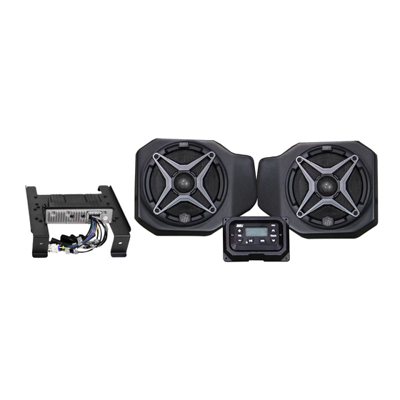
PARTS LIST IMAGES
1. MRB3 Dash Kit
6. USB/AUX Input Port
DASH DISASSEMBLY
A. Remove hood by turning locking pins and lifting up.
- T-40/30/25 Torx Driver - Phillips Screwdriver - Drill - 3/32" Bit
2. MRB3 Controller
7. B-H1221 MRB3 Power &
Ground Connector
A
3. Mounting Plate with
4. MRB3 Controller/Dash
MRB3 Brain
8. 3-Pin T-harness
BO-SS-HPGAT
B. Use a panel tool to extract push pins circled in pink.
Polaris Ranger
2-Speaker with MRB3 Dash Kit
Please read and understand these
!
instructions completely before
installation to avoid possible injury, or
damage to the accessory or vehicle.
- 9/16" Bit
5. Front B-H1149 Speaker
Screws x6
9. Antenna
RG4-2A
- Uni-Bit
Harness
10. Zip Ties
B
Advertisement

Subscribe to Our Youtube Channel
Related Manuals for SSV Works RG4-2A


Summary of Contents for SSV Works RG4-2A
- Page 1 All SSV Works enclosures are covered by a limited lifetime warranty against defects in Please read and understand these material or workmanship. All SSV Works Electronics are covered by a limited 1 year warranty instructions completely before against defects in material or workmanship. All SSV Works Speakers are covered by a installation to avoid possible injury, or limited 1 year warranty against defects in material or workmanship.
- Page 2 D. Lift and disconnect gauge cluster for removal. C. With push pins extracted, lift to remove the cup holder. E. Unscrew (4) torx screws located in upper glove box and F. Extract push pins that are now exposed from removing the remove box.
- Page 3 K. Extract push pins located beneath 12v sockets. L. Remove front dash panel and disconnect the 12v socket harness. M. Unscrew (2) torx screws that were behind the front dash panel. N. Unscrew the two (2) torx screws connecting the dash bracket at the rear of the dash cavity.
- Page 4 S. Make pilot holes using a 3/32” drill bit. T. Drill out the center of the cup holder for the controller cable to be routed through with a 9/16” drill bit. NOTE: Control drill bit depth to avoid puncturing through other side of cup holder.
- Page 5 FRONT KICK PANEL SPEAKER PODS INSTALLATION PARTS LIST IMAGES 1. RG4-F65 Enclosures 2. Enclosure Brackets x 4 3. M6 x 16mm Screws 4. M6 Washers x 8 (small) 4. M6 Washers x 2 (large) (1 pair) x 10 A. Using the supplied M6 screws and small washers, install B.
- Page 6 E. Place the speaker pod in location and resecure the factory screws through the pod brackets on the front and underneath the dash. F. From the inside-top of the dash, secure the top mounting M6 screw and large washer to the pod through the smaller hole next to the routed speaker wire (figure F1).
-
Page 7: Connecting Power
C. Connect the HPGAT harness to an empty port on the factory buss bar located under the hood. THIS CONCLUDES THE INSTALLATION PROCESS. REPLACE THE FACTORY PANELS. QUESTIONS? PLEASE CONTACT SSV WORKS AT 818-991-1778 OR EMAIL SUPPORT@SSVWORKS.COM © 2018 SSV Works, Oxnard, CA 93030 RG4-2A Rev. A 7-17-18...
Need help?
Do you have a question about the RG4-2A and is the answer not in the manual?
Questions and answers