Advertisement
Quick Links
SSV WORKS, 201 N. Rice Ave Unit A, Oxnard, CA 93030
www.SSVworks.com
|
Phone: 818-991-1778
RED
RZR3
FOLLOW THE COLOR CODE ON EACH STEP FOR YOUR VEHICLE'S SPECIFIC INSTRUCTIONS
8
pg
Panels, Dash Disassembly, and Wiring
12
pg
Glovebox Subwoofer Installation
15
pg
Amp Tray Installation
17
pg
Kick Panel Speakers Installation
19
pg
Cage Mount Speakers Installation
22
pg
MRB3 and Dash Kit Installation
|
Fax: 866-293-6751
2014-2018
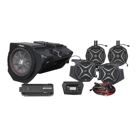
RZ34-Q5A3
RZR 3 and RZR 4
SSV Works 5 Speaker Audio Kit
BLUE
RZR4
2019+
Phase 5
Advertisement

Related Manuals for SSV Works RZ34-Q5A3


Summary of Contents for SSV Works RZ34-Q5A3
- Page 1 RZ34-Q5A3 RZR 3 and RZR 4 SSV Works 5 Speaker Audio Kit SSV WORKS, 201 N. Rice Ave Unit A, Oxnard, CA 93030 Phase 5 www.SSVworks.com Phone: 818-991-1778 Fax: 866-293-6751 BLUE RZR3 RZR4 2014-2018 2019+ FOLLOW THE COLOR CODE ON EACH STEP FOR YOUR VEHICLE’S SPECIFIC INSTRUCTIONS...
-
Page 2: Parts List
All SSV Works enclosures are covered by a limited lifetime warranty against defects in instructions completely before material or workmanship. All SSV Works Electronics are covered by a limited 1 year warranty installation to avoid possible injury, against defects in material or workmanship. All Kicker Speakers are covered by a limited 1 or damage to the accessory or vehicle. - Page 3 All SSV Works Electronics are covered by a limited 1 year warranty against installation to avoid possible injury, defects in material or workmanship. All SSV Works Speakers are covered by a limited 1 year or damage to the accessory or vehicle.
- Page 4 All SSV Works enclosures are covered by a limited lifetime warranty against defects in instructions completely before material or workmanship. All SSV Works Electronics are covered by a limited 1 year warranty installation to avoid possible injury, against defects in material or workmanship. All Kicker Speakers are covered by a limited 1 or damage to the accessory or vehicle.
-
Page 5: Installation Notes
All SSV Works enclosures are covered by a limited lifetime warranty against defects instructions completely before in material or workmanship. All SSV Works Electronics are covered by a limited 1 year installation to avoid possible injury, or warranty against defects in material or workmanship. All Kicker Speakers are covered damage to the accessory or vehicle. - Page 6 All SSV Works enclosures are covered by a limited lifetime warranty against defects in instructions completely before material or workmanship. All SSV Works Electronics are covered by a limited 1 year warranty installation to avoid possible injury, or against defects in material or workmanship. All SSV Works Speakers are covered by a damage to the accessory or vehicle.
-
Page 7: Tools For Installation
All SSV Works enclosures are covered by a limited lifetime warranty against defects in instructions completely before material or workmanship. All SSV Works Electronics are covered by a limited 1 year warranty installation to avoid possible injury, or against defects in material or workmanship. All SSV Works Speakers are covered by a damage to the accessory or vehicle. - Page 8 PANELS AND DASH DISASSEMBLY (ALL MODELS) A. Remove all seats by releasing the handle behind each seat, B. Disconect the negative battery cable from the battery. push forward slightly while lifting up. PANELS AND DASH DISASSEMBLY (RZR3) C. Remove hood by turning locking pins and lifting up. D.
- Page 9 G. Remove the factory dash pocket by first extracting the 10mm bolt on the dash frame (G1). Then pull out the dash pocket with bracket attached (G2) - NOTE this bracket will no longer be used for any part of this installation. Save this screw as it will be use later during the amp plate installation. Extract (2) screws securing the sub dash (G3).
- Page 10 PANELS AND DASH DISASSEMBLY (RZR4) C. Remove hood by turning locking pins and lifting up. D. Unscrew the (4) T40 torx screws and extract the (2) push pins from the top-center dash compartment. Lift and remove the top-center dash compartment. From inside the machine, pull the dash towards you to unclip.
- Page 11 D. Starting from under the hood compartment, feed the connector of the power wire and B-H1912 & B-H1913 rear harness female connector through the grommet into the dash cavity. In order to connect to the amplifier in a later step, pull about 18” of the amp power wire and B-H1912 & B-H1913 into the dash cavity (D1).
- Page 12 I. Starting from under the hood compartment, feed the connector of the power wire, MRB3 power connector, and B-H1912 & B-H1913 rear harness female connector through the grommet into the dash cavity. In order to connect to the amplifier in a later step, pull about 18” of the amp power wire and B-H1912 &...
- Page 13 E. With the dash removed, extract the (2) 10mm bolts retaining the glovebox and remove the glovebox. F. Lift the enclosure into place. Using the factory glove box mounting hardware, fasten the enclosure into place. Pull sub enclosure wiring towards the center of the vehicle to avoid being pinched by the chassis.
- Page 14 I. Feed the sub amp power wire out of the dash cavity through the grommet hole, down the firewall, and back through the center console to the battery. J. Strip back ¼” – ½” of the Red and Black wires (This loom can K.
- Page 15 AMP PLATE INSTALLATION 1. INPUT (FRONT) 2. INPUT (REAR) 3. INPUT (SUB) 4. OUTPUT (SUB) 5. B-H2701 6. OUTPUT (FRONT) 7. OUTPUT (REAR) 8. EXT SWITCH 9. AMP TURN-ON 10. TO POWER INPUT 800 0 .5 AMP 800.5 AMP .5 AMP...
- Page 16 AMP PLATE INSTALLATION (RZR3) Place the pre-installed amp plate with MRB3 Brain on the frame of the dash and line up the hole on the top of the amp plate to the factory hole where the pocket bracket was previously installed (1). Loosely screw in the factory 10mm screw in this hole location.
- Page 17 C. Secure the amp tray by using the 10mm factory bolt at the top, and D. Using a scribe or punch, mark the location of the needed pilot hole two (2) T-30 torx bolts at the bottom mounting locations. on the passenger side of the tray. E.
- Page 18 FRONT KICK PANELS (ALL MODELS) A. Starting at driver side footwell, remove the factory T40 torx B. Place the driver kick pod into location so that both vehicle screw as shown. Save this screw for Step D. screw bosses line up with kick pod brackets. C.
- Page 19 CAGE POD KICKER 6.5” SPEAKER (ALL MODELS) A. Find the best orientation for the speaker on your bar and B. Loosely install the clamp base to the cage mount pod with the screw in the Set Screws in the OPPOSITE holes of where the two (2) 8mm M6 hex head bolts and washers, place the cage clamp will install into.
- Page 20 D. Position the speaker to your liking and tighten the hex head E. From the rear of the center console, route the B-H2195 bolts by hand with a 8mm wrench. harness up to each speaker pod and connect. G. Connect the B-H1912 and B-H1913 speaker harness to the SSV F.
- Page 21 C. Feed in the wires and cable through the factory 12v hole. Keep the D. Feed the plastic nut back through the wires and cables and fuse holder open and empty until it has passed through the hole. screw back onto the port. Hand tighten only. Replace fuse and close fuse holder.
- Page 22 DASH KIT FOR MRB3 (RZR3) A. Take the MRB3 Remote and pass the din cable through the dash kit panel. Once MRB3 remote is laying flat on the dash panel pass (2) M3 Screws through the remote and kit panel. Flip the kit around and use (2) M3 washers and (2) M3 Nuts to secure the MRB3 down into position. Do not over tighten the nuts, this can cause damage to the dash kit panel.
- Page 23 DASH KIT FOR MRB3 (RZR4) B. Using a 3/32” drill bit, drill out each template guide point and a A. Cut the template to size. Align the template onto the face of the pilot hole into the center guide point. compartment and tape template into place.
- Page 24 G1. Connect the power/ground wire. G2. Connect the antenna. Route the antenna G3.Re-assemble dash and route controller cable wire under dash. into dash cavity and connect to MRB3 brain. NOTE Some RZR models come with the ground “GND” terminal not connected as shown.
- Page 27 CONNECTING POWER & GROUND CABLE TO BATTERY (ALL MODELS) Battery Terminal Cable Power Wire Break Break off tab off tab A1. Remove the bottom cover of the fuse holder A2. Extract both fuse holder screws. A3. Attach both the Power Wire and Battery by extracting the 2 screws.
- Page 28 © 2022 SSV Works, Oxnard, CA 93030 RZ34-Q5A3 7-26-22...
Need help?
Do you have a question about the RZ34-Q5A3 and is the answer not in the manual?
Questions and answers