
Related Manuals for SSV Works RZ3-3A


Summary of Contents for SSV Works RZ3-3A
- Page 1 RZ3-3A Polaris RZR XP 1000 & 900 SSV Works 3 Speaker Audio Kit Disassembly, Wire and Amplifier Plate Installation Glovebox Subwoofer Installation Kick Panel Speakers Installation MRB3 and Dash Kit Installation...
-
Page 3: Tools Needed For Installation
All SSV Works enclosures are covered by a limited lifetime warranty against defects in instructions completely before material or workmanship. All SSV Works Electronics are covered by a limited 1 year warranty installation to avoid possible injury, or against defects in material or workmanship. All SSV Works Speakers are covered by a damage to the accessory or vehicle. - Page 4 PANELS AND DASH DISASSEMBLY A. Remove all seats by releasing the handle behind each seat, B. Disconect the negative battery cable from the battery. push forward slightly while lifting up. C. Remove hood by turning locking pins and lifting up. D.
- Page 5 PANELS AND DASH DISASSEMBLY G. Remove the factory dash pocket by first extracting the 10mm bolt on the dash frame (G1). Then pull out the dash pocket with bracket attached (G2) - NOTE this bracket will no longer be used for any part of this installation. Save this screw as it will be use later during the amp plate installation. Extract (2) screws securing the sub dash (G3).
- Page 6 RUNNING AMP POWER CABLE AND REAR SPEAKER WIRE A. Unwrap the tape and pull the rubber wire grommet out of the firewall. B. Pull the MRB3 POWER and GROUND wires through the rubber grommet and feed through the hole in the firewall to the power strip located on the opposite side of the firewall.
- Page 7 RUNNING AMP POWER CABLE AND REAR SPEAKER WIRE TOP VIEW UNDERNEATH VIEW E. Route the front speaker wire through the opening where the firewall and roll cage bar meet on both the driver and passenger side. Leave these wires loose until the front speaker pods are to be installed.
-
Page 9: Parts List
All SSV Works enclosures are covered by a limited lifetime warranty against defects instructions completely before in material or workmanship. All SSV Works Electronics are covered by a limited 1 year installation to avoid possible injury, or warranty against defects in material or workmanship. All SSV Works Speakers are damage to the accessory or vehicle. - Page 10 A. Remove the ten T40 Torx bolts that secure the 2 piece fender. B. Remove the two 10mm bolts the secure factory glove box and Note: there is one screw inside the fender well. Remove the remove the factory glove box two additional screws from the striker plate, slide fender up the cage rail and secure C.
- Page 11 H. For 2014 model year vehicles remove the factory glove box G. For 2015-up model year vehicles, install the supplied bracket door latch. Mount the latch to the supplied bracket and using the short screws provided and adjust forward or back so secure to the enclosure using the short screws provided glove box latch closes tight I.
- Page 13 All SSV Works enclosures are covered by a limited lifetime warranty against defects instructions completely before in material or workmanship. All SSV Works Electronics are covered by a limited 1 year installation to avoid possible injury, or warranty against defects in material or workmanship. All SSV Works Speakers are damage to the accessory or vehicle.
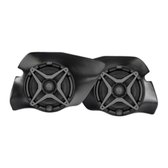
- Page 14 A. Using the utility knife or another cutting tool cut off the two plastic factory nubs in the foot well, cut these as smooth as you can to the panel. NOTE: If pod does not come pre-installed with speaker, do not use provided paper templates. Use the pod mounting holes as your drill template. Hold the pod in position and mark the drill holes through the empty pod using a scribe tool.
- Page 15 C. Drill a pilot hole at the places just marked with a 1/8” drill bit. Then follow up by using a 1/4” drill bit in the lower pilot hole (for mounting the pod) and a 1/2” drill bit in the upper pilot hole (for speaker cable). D.
- Page 16 E. Drill a pilot hole at the places just marked with a 1/8” drill bit. Then follow up by using a 1/4” drill bit for both pilot holes (for mounting the pod). F. Route the speaker cable attached to the pod through the inside footwell 1/2” hole.
- Page 17 RZ3-F65 2017 Polaris RZR Kick Pod, Cut Template Driver Outside Template Drill Point Drill Point Cut along parimeter...
- Page 21 RZ3-F65 2017 Polaris RZR Kick Pod, Cut Template Passenger Outside Template Drill Point Drill Point Cut along parimeter...
-
Page 25: Installation Notes
All SSV Works enclosures are covered by a limited lifetime warranty against defects in instructions completely before material or workmanship. All SSV Works Electronics are covered by a limited 1 year warranty installation to avoid possible injury, or against defects in material or workmanship. All SSV Works Speakers are covered by a damage to the accessory or vehicle. - Page 26 A. Take the MRB3 Remote and pass the din cable through the dash kit panel. Once MRB3 remote is laying fl at on the dash panel pass (2) M3 Screws through the remote and kit panel. Flip the kit around and use (2) M3 washers and (2) M3 Nuts to secure the MRB3 down into position. Do not over tighten the nuts, this can cause damage to the dash kit panel.
- Page 27 Polaris RZR XP 1000 & 900 USB/AUX Input Port SSV WORKS, 201 N. Rice Ave Unit A, Oxnard, CA 93030 www.SSVworks.com | Phone: 818-991-1778 | Fax: 866-293-6751 A. Unscrew and remove the plastic nut from the port. Make sure to B.
- Page 28 40A fuse, screw the 2 screws back in and reattach the fuse holder top. column away from the drive shaft. THIS CONCLUDES THE INSTALLATION PROCESS. REPLACE THE FACTORY PANELS AND SEATS. QUESTIONS? PLEASE CONTACT SSV WORKS AT 818-991-1778 OR EMAIL SUPPORT@SSVWORKS.COM © 2018 SSV Works, Oxnard, CA 93030 RZ3-3A Rev. C 2-1-18...
- Page 29 SAFETY INFORMATION SSV Works Electronics are covered by a limited 1 year warranty against defects in material or workmanship. Labor for replacement of defective components is not covered. All SSV Works Speakers are covered by a limited 1 year warranty against defects in material or workmanship.
-
Page 30: Button Locations And Functions
AMPLIFIER WIRING DIAGRAM BUTTON LOCATIONS AND FUNCTIONS 1. Play/Pause 12v+ Yellow Power On/Off MRB3 Mute 2. Volume Up/Down 3. Mode 4. Track Forward/Back Station Forward/Back Menu Settings Up/Down USB 1A charge input 5. LCD Display does not read USB data Signal ground (Black) AMP turn on... - Page 31 WARRANTY INFORMATION: All SSV Works amplifiers are covered by a limited 1 year warranty against defects in material or workmanship. All SSV Works electronics are covered by a limited 1 year warranty against defects in material POWER / PROTECT LED LIGHT or workmanship.
- Page 32 Inputs UNIT ADJUSTING AMPLIFIER INPUT GAIN CONTROLS The WP-A360s4 has been tuned to match SSV Works source units. If you are using a non SSV Works source BATTERY you unit follow the instructions below to adjust the input gain settings.
- Page 33 All SSV Works enclosures are covered by a limited lifetime warranty against defects instructions completely before in material or workmanship. All SSV Works Electronics are covered by a limited 1 year installation to avoid possible injury, or warranty against defects in material or workmanship. All SSV Works Speakers are damage to the accessory or vehicle.
- Page 34 A. Remove the ten T40 Torx bolts that secure the 2 piece fender. B. Using the utility knife or another cutting tool cut off the two Note: there is one screw inside the fender well. Remove the plastic factory nubs in the foot well, cut these as smooth as two additional screws from the striker plate, slide fender up you can to the panel.
- Page 35 D. Drill a pilot hole at the places just marked with a 1/8” drill bit. Then follow up by using a 1/4” drill bit in the lower pilot hole (for mounting the pod) and a 1/2” drill bit in the upper pilot hole (for speaker cable). E.
-
Page 36: Wiring Instructions
If you are not using the WP-H1149 the amplifier wiring instructions for harness, simply cut off the two-pin connector more detailed wiring information. and follow the wiring instruction below. RZ3-F65 © 2017 SSV Works, Oxnard, CA 93030 RZ3-F65 Rev. A 5-19-17... - Page 37 INSTALLATION NOTES If the vehicle has SSV Works front kick panels (RZ3-FKP65) installed, the passenger side kick panel will need to be removed prior to installation of the WP-RZ3GBS10. Removal of the passenger fender is not required (Step C); however it will make the installation and...
- Page 38 A. Remove the hood, remove the two T40 Torx bolts that secure B. Remove the two T40 Torx bolts that secure the front dash. top center dash. From inside the vehicle, release the dash Carefully release the panel clips along the perimeter of the by gently pulling toward the rear of the vehicle.
- Page 39 G. To properly align the box, slide the box firmly toward the front of the vehicle. It should sit approximately 1/4” from the factory glove box mount. If not properly installed, the dash of the vehicle will not securely push back into position. I.
- Page 40 4 pin connector to that location) be sure to avoid moving parts and sharp edges while routing the cables. If you have purchased the optional SSV Works Subwoofer Level Control (WP-ASLC), plug in now and route to dash mounting location C.
Need help?
Do you have a question about the RZ3-3A and is the answer not in the manual?
Questions and answers