Table of Contents
Advertisement
Available languages
Available languages
Quick Links
Download this manual
See also:
Instruction Manual
I N S T R U C T I O N M A N U A L
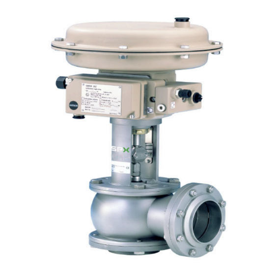
APV DELTA RG4 DN25-150,1"-4"
M O D U L AT I N G VA LV E
S A F E T Y A G A I N S T E X P L O S I O N - F O R S P E C I F I C AT E X - A P P L I C AT I O N S
F O R M N O . : H 3 3 3 9 2 7
R E V I S I O N : U K - 0 - AT E X
R E A D A N D U N D E R S TA N D T H I S M A N U A L P R I O R TO O P E R AT I N G O R S E RV I C I N G T H I S P R O D U C T.
Advertisement
Table of Contents

Related Manuals for SPX FLOW APV DELTA RG4


Summary of Contents for SPX FLOW APV DELTA RG4
- Page 1 I N S T R U C T I O N M A N U A L APV DELTA RG4 DN25-150,1”-4” M O D U L AT I N G VA LV E S A F E T Y A G A I N S T E X P L O S I O N - F O R S P E C I F I C AT E X - A P P L I C AT I O N S F O R M N O .
- Page 3 Directive on the Protection against Explosion 2014/34/EU ATEX (superseding 94/9/EC) for Equipment Category -/2G IIB TX For official inspections, SPX FLOW presents a technical documentation according to Appendix VII of the Machinery Directive, this documentation consisting of documents of the development and construction, description of measures taken to meet the conformity and to correspond with the basic requirements on safety and health, incl.
-
Page 5: Table Of Contents
APV_RG4_ATEX_UK-0_032018.indd Content Page General Terms 1.1. Symbols 1.2. Responsibility for ATEX certification - Scope of supply Safety Instructions 3 - 4 Identification of valve, Temperature classes, Responsibilites 5 - 6 3.1. Identification of valves for application in ATEX environment 3.2. Temperature classes and permissible temperatures 3.3. Responsibilities Intended Use Mode of Operation 7 - 8 5.1. General terms Cleaning 6.1. Flow areas Installation 9 - 10 7.1. General terms 7.2. -
Page 7: General Terms
1.2. Responsibility for ATEX certification - scope of supply SPX FLOW will be held responsible only for the valves supplied and selected according to the operating conditions indicated by the customer or end user and as stated in the order confirmation. If in doubt, contact your SPX FLOW partner. -
Page 8: Safety Instructions
APV_RG4_ATEX_UK-0_032018.indd Safety Instructions Danger! Do not touch the open valve body or the yoke! Risk of injury due to sudden valve operation. Risk of injury in dismantled valve state due to sudden valve operation. Regular maintenance including the replacement of all seals and bearing bushes must be scheduled in order to prevent leakages and discharge of liquids.. -
Page 9: Safety Instructions
APV_RG4_ATEX_UK-0_032018.indd Safety Instructions Installation, connection, start-up, maintenance and repair work must only be carried out by qualified personnel. The following aspects must be observed: The instructions of this manual together with all relevant instructions for the components, equipment and installations installed. Warnings and installations fixed to the components. The specific regulations for and requirements to the system in which the valve is installed. The currently valid regional, national and international regulations. -
Page 10: Temperature Classes And Permissible Temperatures
All data (temperature classes) refer to an ambient temperature of 0°C to 40°C. If the ambient temperature is above 40°C, the temperature difference must be adjusted. In all cases, contact your responsible SPX FLOW representative! Modulating Valve DELTA RG4-ATEX Instruction Manual: UK-0... -
Page 11: Responsibilities
APV_RG4_ATEX_UK-0_032018.indd Identification of valves, Temperature classes, Responsibilities 3.3. Responsibilites It is within the operator`s responsibility to ensure that the specified product temperatures are not exceeded and that regular inspections and maintenance are carried out to provide for proper function of the valve. Intended Use The intended use as field of application of the modulating valve DELTA RG4 is the flow and pressure regulation of liquids and gases. - Page 12 APV_RG4_ATEX_UK-0_032018.indd Mode of Operation 5.1. General terms Hygienic modulating valves DELTA RG4 are used for the continuous control of liquid flows in beverage and food positioner technology as well as in the chemical and pharmaceutical integrated industry. Modulating valves are suited for the flow and pressure control of liquids and gases.
-
Page 13: Mode Of Operation
APV_RG4_ATEX_UK-0_032018.indd Mode of Operation Depending on the specific requirement, the modulating valve can be operated either with spring opening or with spring closing function. MFS - diaphragm actuator, spring closing The actuator opens by actuating pressure and closes by spring pressure. MFH - diaphragm actuator, spring opening. The actuator closes by actuating pressure and opens by spring pressure. -
Page 14: General Terms
APV_RG4_ATEX_UK-0_032018.indd Cleaning 6.1. Flow areas The passages of the valve are cleaned by the cleaning liquid during cleaning of the connected pipelines. The compatibility of the individually selected cleaning processes and liquids with the respective seal material must be verified. Installation 7.1. General terms Installation must be undertaken in such a way that liquids can drain off the valve housing and should preferably be carried out in vertical position. -
Page 15: Welding Instructions
APV_RG4_ATEX_UK-0_032018.indd Installation 7.2. Welding instructions Welding may only be carried out by certified welders (DIN EN ISO 9606-1). (Seam quality DIN EN ISO 5817). Before welding, the insert and the seals must be dismantled. During tacking, the lower and lateral flange must be connected with the housing. -
Page 16: Dimensions / Weights
APV_RG4_ATEX_UK-0_032018.indd Dimensions / Weights 8.1. Integrated Ø E positioner (metric dimensions) dimensions in mm weight actuating surface in kg Ø Di Ø E (cm²) 163,5 49,5 10,8 11,7 169,5 55,5 12,1 15,1 12,2 175,5 61,5 12,7 15,7 15,1 184,0 70,0 17,4 16,2 191,5 77,5 19,8... - Page 17 APV_RG4_ATEX_UK-0_032018.indd Dimensions / Weights 8.2. Integrated Ø E positioner (Inch dimensions) dimensions in mm weight actuating surface in kg Inch Ø Di Ø E (cm²) 367,2 1" 161,6 47,5 22,2 375,2 10,8 379,9 11,7 1,5" 387,9 167,5 53,9 34,9 12,1 407,9 15,1 392,6 12,2 2"...
- Page 18 APV_RG4_ATEX_UK-0_032018.indd Technical Data 9.1. General data max. premissible operating pressure: DN 25 - DN 65 25 bar DN 80 - DN 100 16 bar DN 125 - DN 150 10 bar correcting ratio: 1 : 50 standard design: housing 1.4404 inner surface electro- polished Ra 0,8μm external surface satin finish air pressure of diaphragm actuator:...
-
Page 19: Technical Data
APV_RG4_ATEX_UK-0_032018.indd Technical Data 9.2. Compressed air quality Compressed air quality: quality class according to ISO 8573-1 Content of solid particles: quality class 3, max. number of particles per m³ 10000 of 0,5 μm < d ≤ 1,0 μm 500 of 1,0 μm < d ≤ 5,0 μm Content of water: quality class 3, max. dew point temperature -20 °C For installations at lower temperatures or at higher altitudes, additional measures must be considered to reduce... -
Page 20: Materials
APV_RG4_ATEX_UK-0_032018.indd Technical Data 9.3. Materials RG4 components Material housing, valve shaft, housing 1.4404 (DIN EN 10088) cover, valve seat, flange valve yoke 1.4308 (DIN EN 10088) coupling (compl.) 1.4301 (DIN EN 10088) screws, nuts Standard: EPDM housing seal Optional: HNBR, FPM, VMQ seat seal, shaft seal, Standard: EPDM FGN1 seal... - Page 21 APV_RG4_ATEX_UK-0_032018.indd Technical Data 9.4. Kvs - values in m³/h, valve stroke, Ø valve seat (S) DN25 DN40 DN 50 DN 65 DN 80 DN 100 DN 125 DN 125 DN 150 stroke stroke stroke stroke stroke stroke stroke stroke stroke 15 mm 15 mm 15 mm 15 mm 15 mm 15 mm 15 mm 30 mm 30 mm Kvs S Ø...
-
Page 22: Maintenance
APV_RG4_ATEX_UK-0_032018.indd 10. Maintenance The maintenance intervals depend on the corresponding application and are to be determined by the operator himself carrying out temporary checks. The valve must not be cleaned with products containing abrasive or polishing material. Especially the valve shaft must not, under any circumstances, be cleaned with such agents. -
Page 23: Service Instructions
APV_RG4_ATEX_UK-0_032018.indd 11. Service Instructions Corresponding spare parts see Spare Parts List: RN ATEX 01.170.1, RN ATEX 01.170.0 11.1. Dismantling from line system Before start of assembly the operator must make sure that an explosive atmohsphere does not exist (detection/measurement of potential concentration of hazardous substances). Alternatively, use spark-resistant tools! 1. Shut off line pressure and drain lines if possible. 2. - Page 24 APV_RG4_ATEX_UK-0_032018.indd 11. Service Instructions 11.3. Disassembly of the valve for change of flow rate and characteristics 1. See chapter 11.2. pos. 1. - 4. 2. If, in case of change of flow rates, the diaphragm actuator (28) must be exchanged, loosen nut by means of hammer and chisel and take off actuator.
- Page 25 APV_RG4_ATEX_UK-0_032018.indd 11. Service Instructions 11.4. Assembly of the valve and installation of new parts Attention! To ensure a trouble-free assembly and a high service life of all wear parts (seals, guides, etc.), all parts must be slightly greased. Sharp-edged tools (screwdrivers or similar tools) must not be used for the installation to avoid damage to the parts and provide their faultless function.
-
Page 26: Service Instructions
APV_RG4_ATEX_UK-0_032018.indd 11. Service Instructions 11.5. Assembly of valve to change flow rates and characteristics 1. The available wear parts (seals and guides) have to be checked for their proper function. Damaged parts must be replaced immediately. (designations and ref.-No. see spare parts list pos. 14). 2. See chapter 11.4. pos. 1. - 6. 3. -
Page 27: Installation Of Seat Seal
APV_RG4_ATEX_UK-0_032018.indd Installation of Seat Seal 12.1. Manual installation of seat seal (pos. 12). Before assembly provide the seat seal with a thin layer of grease. The groove for the seat seal must not be greased. Clamp the valve shaft into a vice. The valve shaft must not be damaged. Use protective cloth! Press the slightly greased seal at four spots with the wide side to the front into the groove (see sketch 1). -
Page 28: Trouble Shooting
APV_RG4_ATEX_UK-0_032018.indd 13. Trouble Shooting Failure Remedy Leakage between upper housing flange and yoke flange Replace housing seal. Leakage between lower housing flange and Replace housing seal and flange seal. counterflange Leakage at lateral flange connection Replace flange seal. Positioner type 3277 Check screw connection, if necessary replace rolling Air escapes from diaphragm actuator. -
Page 29: Spare Parts Lists
APV_RG4_ATEX_UK-0_032018.indd 14. Spare parts list The reference numbers of the spare parts for the different valve designs and sizes are included in the attached spare parts drawings with corresponding lists. Please indicate the following data to place an order for spare parts: - required number of parts - reference number - designation. -
Page 31: Rn Atex 01.170.1
Name: Trytko Geprüft: Knöchel Ersatzteilliste: spare parts list SPX FLOW Regelventil RG41- Pneumatischer Stellantrieb MAT3277 (MFS oder MFH) 120,240,350,700cm2, Germany digitaler el.-pneumatischer Stellungsregler IP3730; lineare oder gleichproz. Kennlinie. -Ex II -/2G IIB TX Blatt Modulating valve RG41- with diaphragm actuator MAT3277 (spring: closed or open) 120,240,350,700cm2 digital electro-pneumatic positioner IP3730;... -
Page 43: Rn Atex 01.170.0
Name: Trytko Geprüft: Knöchel Ersatzteilliste: spare parts list SPX FLOW Regelventil RG41- Pneumatischer Stellantrieb MAT3277 (MFS oder MFH) 120,240,350,700cm2, Germany digitaler el.-pneumatischer Stellungsregler IP3730; lineare oder gleichproz. Kennlinie. -Ex II -/2G IIB TX Blatt Modulating valve RG41- with diaphragm actuator MAT3277 (spring: closed or open) 120,240,350,700cm2 digital electro-pneumatic positioner IP3730;... -
Page 61: Rn Atex 01.170.13-4
Geprüft: Knöchel Knöchel ATEX - Ausführungen / designs Ersatzteilliste: spare parts list SPX FLOW RG4-Pneumat. Stellantrieb MAT 3277 MFS-federschließend und MFH-federhebend Germany mit digitalem elektro-pneumatischem Stellungsregler IP3730 Blatt RG4-Pneum. actuator MAT 3277 spring closed and open with digital el.-pneum. positioner RN ATEX 01.170.13-4... -
Page 62: Modulating Valve
F: (+48) 52 525 99 09 SPX FLOW reserves the right to incorporate the latest design and material changes without notice or obligation. Design features, materials of construction and dimensional data, as described in this manual, are provided for your information only and should not be relied upon unless confirmed in writing.
Need help?
Do you have a question about the APV DELTA RG4 and is the answer not in the manual?
Questions and answers