Table of Contents
Advertisement
Quick Links
I N S T R U C T I O N M A N U A L
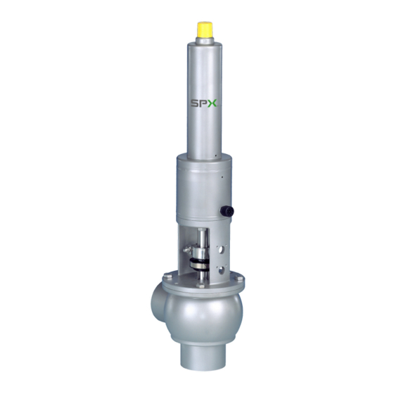
APV DELTA UF3(A) / UFR3(A) DN25-100,1"-4"
R E L I E F VA LV E
S A F E T Y A G A I N S T E X P L O S I O N - F O R S P E C I F I C AT E X - A P P L I C AT I O N S
F O R M N O . : H 3 3 2 8 4 4
R E V I S I O N : U K - 0 - AT E X
R E A D A N D U N D E R S TA N D T H I S M A N U A L P R I O R TO O P E R AT I N G O R S E RV I C I N G T H I S P R O D U C T.
Advertisement
Table of Contents

Related Manuals for SPX FLOW APV DELTA UF3


Summary of Contents for SPX FLOW APV DELTA UF3
- Page 1 I N S T R U C T I O N M A N U A L APV DELTA UF3(A) / UFR3(A) DN25-100,1”-4” R E L I E F VA LV E S A F E T Y A G A I N S T E X P L O S I O N - F O R S P E C I F I C AT E X - A P P L I C AT I O N S F O R M N O .
- Page 3 Directive on the Protection against Explosion 2014/34/EU ATEX (superseding 94/9/EC) for Equipment Category -/2G IIB TX For official inspections, SPX FLOW presents a technical documentation according to Appendix VII of the Machinery Directive, this documentation consisting of documents of the development and construction, description of measures taken to meet the conformity and to correspond with the basic requirements on safety and health, incl.
-
Page 5: Table Of Contents
APV_UF3 ATEX_UK-0_122018.indd Content Page General Terms 1.1. Symbols 1.2. Responsibility for ATEX certification - Scope of supply Safety Instructions 3 - 4 Identification of valves, Temperature classes, Responsibilities 5 - 6 3.1. Identification of valves for application in ATEX environment 3.2. Temperature classes and permissible temperatures 3.3. Responsibilities Intended Use Mode of Operation 5.1. General terms Auxiliary Equipment 6.1. Seat lift actuator 6.2. Valve seat variants 6.3. -
Page 7: General Terms
1.2. Responsibility for ATEX certification - scope of supply SPX FLOW will be held responsible only for the valves supplied and selected according to the operating conditions indicated by the customer or end user and as stated in the order confirmation. If in doubt, contact your local supplier. -
Page 8: Safety Instructions
Danger to life! Actuators which are no longer used or defective must be diposed in professional manner. Defective actuators must be returned to your SPX FLOW representative for their professional disposal and free of charge for you. Please address to your local SPX FLOW representative. - Page 9 APV_UF3 ATEX_UK-0_122018.indd Safety Instructions Installation, connection, start-up, maintenance and repair work must only be carried out by qualified personnel. The following aspects must be observed: The instructions of this manual together with all relevant instructions for the components, equipment and installations installed. Warnings and installations fixed to the components. The specific regulations for and requirements to the system in which the valve is installed. The currently valid regional, national and international regulations.
-
Page 10: Identification Of Valves, Temperature Classes, Responsibilities
All data (temperature classes) refer to an ambient temperature of 0°C to 40°C. If the ambient temperature is above 40°C, the temperature difference must be adjusted. In all cases, contact your responsible SPX FLOW representative! Relief Valve DELTA UF3-ATEX Instruction Manual UK-0... -
Page 11: Responsibilities
APV_UF3 ATEX_UK-0_122018.indd Identification of valves, Temperature classes, Responsibilities 3.3. Responsibilites It is within the operator`s responsibility to ensure that the specified product temperatures are not exceeded and that regular inspections and maintenance are carried out to provide for proper function of the valve. Intended Use The intended use as field of application of the DELTA UF3 relief valve is to prevent the max. -
Page 12: Mode Of Operation
APV_UF3 ATEX_UK-0_122018.indd Mode of Operation 5.1. General terms The valve has been developed for use in the brewing and beverage, dairy and food industries as well as for chemical and pharmaceutical DELTA UF3/ UFR3 applications. relief valve The valves are designed for universal applications and stand out for their increased mechanical reliability and absolute ease of service. -
Page 13: Auxiliary Equipment
APV_UF3 ATEX_UK-0_122018.indd Auxiliary Equipment 6.1. Seat lift actuator fig. 6.1. The UF3 valve can be equipped with a seat lift cylinder if requied for cleaning technical reasons . (see chapter 7.) 6.2. Valve seat variants (fig. 6.2.) Valve seat in flat and conical design, for special requirements, are available. Through the use of a valve seat with regulating cone, seat lift actuator the flow behaviour at low flow quantities is improved and a "softer"... -
Page 14: Cleaning
APV_UF3 ATEX_UK-0_122018.indd Cleaning Optimum cleaning is given if the seat lift actuator (E) drives the valve seat into the position “on” during the cleaning process (fig. 5.1). During this process, the cleaning liquid can flush the seal surfaces. After termination of the cleaning step, the seat lift actuator is vented and the valve seat moves into "closed"... -
Page 15: Installation
APV_UF3 ATEX_UK-0_122018.indd Installation 8.1. General terms Installation has to be done in such a way that liquids can drain off the valve housing. Vertical position is preferred. Valves can be welded direct into the pipeline (valve insert completely dismantable). After the installation, the set value must be adjusted by a pressure gauge. -
Page 16: Welding Instructions
APV_UF3 ATEX_UK-0_122018.indd Installation 8.2. Welding Instructions Before welding of the valve, the valve insert must be dismantled from the housing. Careful handling to avoid damage to the parts is necessary. Welding should only be carried out by certified welders (DIN EN ISO 9606-1). (Seam quality DIN EN ISO 5817). -
Page 17: Dimensions / Weights
APV_UF3 ATEX_UK-0_122018.indd Dimensions / Weights spring cylinder ØK spring cylinder with seat lift actuator without / with regulating cone weight without/with seat lift act. *** dimension without/with seat lift act. pressure range Weight in Ø Di Ø K (bar) with- with- with- with- with- Inch flat cone with Inch 1" 0-6,8 0-5,4 22,2 1" 0-10,0 0-10,0 22,2... -
Page 18: Technical Data
APV_UF3 ATEX_UK-0_122018.indd 10. Technical Data 10.1. General data Product-wetted parts: 1.4404 (DIN EN 10088) Other parts: 1.4301 (DIN EN 10088) Seals: standard design EPDM option: HNBR, VMQ, FPM max. line pressure 10 bar or acc. to drawing data max. operating temperature: 135°C EPDM, HNBR *FPM, *VMQ short-term load: 140°C EPDM,... -
Page 19: Maintenance
APV_UF3 ATEX_UK-0_122018.indd 11. Maintenance The maintenance intervals depend on the corresponding application and are to be determined by the operator himself carrying out temporary checks. The valve must not be cleaned with products containing abrasive or polishing material. Especially the valve shaft must not, under any circumstances, be cleaned with such agents. - Page 20 APV_UF3 ATEX_UK-0_122018.indd 11. Maintenance Additionally required maintenance for applications in ATEX environment Valve maintenance Note for spring-bearing components Functional test, 1 x per year visual inspection of actuator stroke and control of abnormal running noise of the spring Change interval In case of damage, (spring cylinder and seat lift incomplete actuator movement, actuator)
-
Page 21: Service Instructions
APV_UF3 ATEX_UK-0_122018.indd 12. Service Instructions Corresponding spare parts list: RN ATEX 01.054.53 12.1. Dismantling from the line system Before start of maintenance and assembly the operator must make sure that an explosive atmohsphere does not exist (detection/ measurement of potential concentration of hazardous substances). Alternatively, use spark-resistant tools! 1. Shut off line pressure in the product line and drain lines if possible. 2. -
Page 22: Dismantling Of Wear Parts (Product-Wetted Parts)
APV_UF3 ATEX_UK-0_122018.indd 12. Service Instructions 12.2. Dismantling of wear parts (product-wetted parts) UF3 - without seat lift actuator 1. Remove housing screws (7) from housing cover (6). 2. Release screw of coupling (13) and dismantle. 3. Take the valve shaft (3) from the housing cover, simultaneously removing the operating cam (12) and the intermediate piece (14) of the UF valve without seat lift actuator. -
Page 23: Installation Of Seals And Assembly Of Valve
APV_UF3 ATEX_UK-0_122018.indd 12. Service Instructions 12.4. Installation of seals and assembly of valve 1. Fasten the spring cylinder (21) at the yoke (15) by the screws (16). 2. Insert the guide bush (9) in the guide ring (8) and press the complete unit into the yoke flange. 3. Insert the greased seal parts (4, 5) into the groove of the housing cover. -
Page 24: Installation Of Valve
APV_UF3 ATEX_UK-0_122018.indd 12. Service Instructions 12.5. Installation of valve 1. Place the complete valve insert carefully into the valve housing (1). 2. Enter the screws (10) and tighten them crosswise. 3. UF3 valve with seat lift actuator: mount the pneumatic air lines. 4. Installation of valve feedback. basic adjustment: Push the proximity switch into the holder with a 2 mm distance to the operating cam... -
Page 25: Installation Of Seat Seal
APV_UF3 ATEX_UK-0_122018.indd 13. Installation of Seat Seal 13.1 Installation of seat seal (2) in valve shaft The assembly tool (fig. 13.1) consists of: thrust ring ring with venting nose housing threaded bolt thrust ring 1. Insert the valve shaft into the housing in such a way that the seal groove is in the housing. 2. -
Page 26: Trouble Shooting
APV_UF3 ATEX_UK-0_122018.indd 14. Trouble Shooting Failure Remedy Valve closed Replace seat seal (2, 2.1). Leakage at discharge side Check line pressure (max. 10 bar). Check control of seat lift actuator. Check housing seal (7) and shaft seal (4, 5), replace Leakage between housing and yoke flange damaged seals. -
Page 27: Spare Parts Lists
APV_UF3 ATEX_UK-0_122018.indd 15. Spare Parts Lists The reference numbers of the spare parts for the different valve designs and sizes are included in the attached spare parts drawings with corresponding lists. Please indicate the following data to place an order for spare parts: number of required parts reference number designation... -
Page 29: Rn Atex 01.054.53
Trytko Trytko Geprüft: Goebel Ersatzteilliste: spare parts list SPX FLOW Überströmventil / Relief valve UF3, UFE3, UFR3, UFRE3 -Ex II -/2G IIB TX Germany Ausführungen: I. Federzylinder und II. Federzylinder mit Anlüftzylinder Blatt Designs: I. spring cylinder and II. spring cylinder with seat lift actuator RN ATEX 01.054.53... - Page 31 Trytko Trytko Geprüft: Goebel Ersatzteilliste: spare parts list SPX FLOW Überströmventil / Relief valve UF3, UFE3, UFR3, UFRE3 -Ex II -/2G IIB TX Germany Ausführungen: I. Federzylinder und II. Federzylinder mit Anlüftzylinder Blatt Designs: I. spring cylinder and II. spring cylinder with seat lift actuator RN ATEX 01.054.53...
- Page 40 F: (+48) 52 525 99 09 SPX FLOW reserves the right to incorporate the latest design and material changes without notice or obligation. Design features, materials of construction and dimensional data, as described in this manual, are provided for your information only and should not be relied upon unless confirmed in writing.
Need help?
Do you have a question about the APV DELTA UF3 and is the answer not in the manual?
Questions and answers