Table of Contents
Advertisement
Quick Links
Advertisement
Table of Contents

Related Manuals for SPX FLOW APV DELTA RG4


Summary of Contents for SPX FLOW APV DELTA RG4
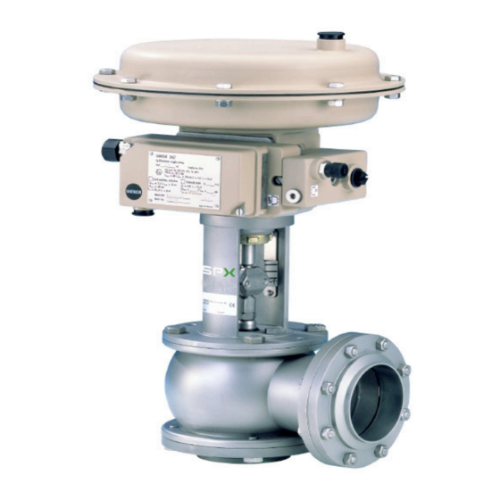
- Page 1 I N S T R U C T I O N M A N U A L APV DELTA RG4 M O D U L AT I N G VA LV E F O R M N O . : 1 7 0 7 1 9 R E V I S I O N : U K - 5 R E A D A N D U N D E R S TA N D T H I S M A N U A L P R I O R TO O P E R AT I N G O R S E RV I C I N G T H I S P R O D U C T.
- Page 3 Directives 2006/42/EC (superseding 89/392/EEC and 98/37/EC) and ProdSG (superseding GPSG - 9.GPSGV). For official inspections, SPX FLOW presents a technical documentation according to Appendix VII of the Machinery Directive, this documentation consisting of documents of the development and construction, description of measures taken to meet the conformity and to correspond with the basic requirements on safety and health, incl.
-
Page 5: Table Of Contents
APV_RG4_UK-6_092017.qxp Contents: Page General Terms Safety Instructions Mode of Operation 2 - 3 Intended Use Installation Welding Instructions Maintenance Materials 5 - 6 Dimensions 6 - 10 Installation of integrated valve positioner (metric dimensions) Installation of integrated valve positioner (inch dimensions) Installation of valve positioner according to NAMUR (metric dimensions) Installation of valve positioner according to NAMUR (inch dimensions) Technical Data... -
Page 7: General Terms
APV_RG4_UK-6_092017.qxp General Terms This instruction manual should be read carefully by the competent operating and maintenance personnel. We point out that we will not accept any liability for damage or malfunctions resulting from the non-compliance with this manual. Descriptions and data are subject to technical changes. Safety Instructions DANGER! - The technical safety symbol draws your attention to important... -
Page 8: Mode Of Operation
APV_RG4_UK-6_092017.qxp Mode of Operation - The table (item 11) shows the parts which have to be replaced if flow rates are changed. The design of the valves with regard to the actuating pressure range or flow rate is made by the manufacturer. -
Page 9: Intended Use
APV_RG4_UK-6_092017.qxp Intended Use The intended use as field of application of the DELTA RG4 modulating valve is the continuous control of liquid flows in beverage and food technology as well as in the chemical and pharmaceutical industry. Arbitrary, constructive changes at the valve will influence safety as well as the intended functionality of the valve and are not permissible. -
Page 10: Materials
APV_RG4_UK-6_092017.qxp Maintenance - Dismantling and installation of valve seat / valve cone according to Service Instructions (item 9). - Dismantling and installation of seals according to Service Instructions. - All seals should be lightly greased before being installed. Recommendation: APV assembly grease for EPDM and FPM (0,75 kg/ can - Ref.-No. -
Page 11: Materials
APV_RG4_UK-6_092017.qxp Materials Part : Material: Diaphragm actuator - diaphragm shells sheet steel plastic coated - diaphragm NBR or EPDM with fabric insert - connection rod, intermediate piece 1.4301 (DIN EN 10088) - springs 1.1250 or 1.7102 plastic coated Valve positioner - housing aluminium pressure die casting,plastic coated or... - Page 12 APV_RG4_UK-6_092017.qxp Dimensions 8.1 Installation of Ø E integrated valve positioner (metric dimensions) actuating surface weight Ø D Ø E (cm²) in kg 163,5 49,5 10,8 11,7 169,5 55,5 12,1 15,1 12,2 175,5 61,5 12,7 15,7 15,1 184,0 70,0 17,4 16,2 191,5 77,5 19,8...
- Page 13 APV_RG4_UK-6_092017.qxp Dimensions 8.2 Installation of Ø E integrated valve positioner (inch dimensions) actuating surface weight Inch Ø D Ø E (cm²) in kg 367,2 1” 161,6 47,6 22,2 375,2 10,8 379,9 11,7 1,5” 387,9 167,9 53,9 34,9 12,1 407,9 15,1 392,6 12,2 2”...
- Page 14 APV_RG4_UK-6_092017.qxp Dimensions 8.3 Installation of Ø E valve positioner according to NAMUR (metric dimensions) actuating surface weight Ø D Ø E (cm²) in kg 163,5 49,5 10,8 11,7 169,5 55,5 12,1 15,1 12,2 175,5 61,5 12,7 15,7 15,1 184,0 70,0 17,4 16,2 191,5...
-
Page 15: Dimensions
APV_RG4_UK-6_092017.qxp Dimensions 8.4 Installation of valve positioner Ø E according to NAMUR (inch dimensions) actuating surface weight Inch Ø D Ø E (cm²) in kg 278,2 1” 161,6 47,6 22,2 271,2 10,8 290,9 11,7 1,5” 283,9 167,9 53,9 34,9 12,1 303,9 15,1 303,6... -
Page 16: Technical Data
APV_RG4_UK-6_092017.qxp Technical Data 9.1. General data - premissible operating pressure DN 25 - 65 / 1” - 2,5” 25 bar DN 80 - 100 / 3” - 4” 16 bar DN 125 - 150 10 bar - correcting ratio 1: 50 - standard design housing 1.4404 inner surface... -
Page 17: Technical Data
APV_RG4_UK-6_092017.qxp Technical Data 9.3. Kvs - values in m³/h, valve stroke, Ø valve seat (S) DN25 DN40 DN 50 DN 65 DN 80 DN 100 DN 125 DN 125 DN 150 stroke stroke stroke stroke stroke stroke stroke stroke stroke 15 mm 15 mm 15 mm... -
Page 18: Service Instructions
APV_RG4_UK-6_092017.qxp Service Instructions 10.1. Dismantling from the line system (The item numbers refer to the spare parts drawings.) 1. Shut off line pressure. 2. Shut off and disconnect air control line. 3. Shut off control power and disconnect connecting line. 4. - Page 19 APV_RG4_UK-6_092017.qxp Service Instructions 10.2. Dismantling of valve to replace wear parts 1. See chapter 10.1. items 1. - 7. 2. Loosen fastening screws (14) and take valve insert with positioner and diaphragm actuator out of the housing (1). If necessary, screw two fastening screws (14) into the bores provided at the valve yoke (12) and push insert out of the housing.
- Page 20 APV_RG4_UK-6_092017.qxp Service Instructions 10.4. Assembly of the valve and installation of new parts CAUTION! To ensure a trouble-free assembly and a high service life of all wear parts (seals, guides, etc.), all parts must be slightly greased. Sharp-edged tools (screwdrivers or similar tools) must not be used for the installation to avoid damage to the parts and provide their faultless function.
-
Page 21: Service Instructions
APV_RG4_UK-6_092017.qxp Service Instructions 10.5. Assembly of valve to change flow rates and characteristics Parts to be replaced - please see item 11. 1. The available wear parts (seals and guides) have to be checked for their proper function. Damaged parts must be replaced immediately. (designations and ref.-No. - Page 67 Trytko C.Keil Geprüft: Knöchel Knöchel Knöchel Ersatzteilliste: spare parts list SPX FLOW RG4-Pneumat. Stellantrieb MAT 3277 MFS-federschließend und MFH-federhebend Germany mit digitalem elektro-pneumatischem Stellungsregler IP3730 Blatt RG4-Pneum. actuator MAT 3277 spring closed and open with digital el.-pneum. positioner RN 01.170.13-1...
- Page 68 Knöchel Knöchel Knöchel Knöchel Ersatzteilliste: spare parts list SPX FLOW RG4-Pneumat. Stellantrieb MAT 3277 MFS-federschließend und MFH-federhebend Germany mit integriertem Stellungsregler (el-pneum. und pneum.) IP 3767, IP 3725 und P 3766 Blatt RG4-Pneum. actuator MAT 3277 spring closed and open with integrated positioner RN 01.170.13-2...
- Page 69 08-44-001/15 H162486 Datum: 21.05.14 24.07.15 02.03.16 Name: Trytko Trytko Trytko Geprüft: Knöchel Knöchel Knöchel Ersatzteilliste: spare parts list SPX FLOW RG4-Pneumat. Stellantrieb MAT 271 MFS-federschließend und MFH- Germany federhebend Blatt RG4-Pneum. actuator MAT 271 spring closed and open RN 01.170.13-3...
- Page 70 Name: Trytko Trytko Geprüft: Knöchel Knöchel Ersatzteilliste: spare parts list SPX FLOW RG4-Pneumat. Stellantrieb MAT 3277 MFS-federschließend und MFH-federhebend Germany mit digitalem elektro-pneumatischem Stellungsregler IP3730 Blatt RG4-Pneum. actuator MAT 3277 spring closed and open with digital el.-pneum. positioner RN01.170.13-4 IP 3730...
- Page 76 F: (+48) 52 525 99 09 SPX FLOW reserves the right to incorporate the latest design and material changes without notice or obligation. Design features, materials of construction and dimensional data, as described in this manual, are provided for your information only and should not be relied upon unless confirmed in writing.
Need help?
Do you have a question about the APV DELTA RG4 and is the answer not in the manual?
Questions and answers