Puls DIMENSION CP Series Manual
24 v, 10 a, 240 w, single phase
Hide thumbs
Also See for DIMENSION CP Series:
- Manual (278 pages) ,
- Quick start manual (29 pages) ,
- User manual (28 pages)
Table of Contents
Advertisement
Quick Links
CP-Series
P
D
RODUCT
ESCRIPTION
Th
e CP10.241-ETC is a high-quality power supply based on
the popular CP10 series. With the integrated EtherCAT
interface the unit is giving access to real-time and recorded
data informing about the condition of the power supply
itself and the power line. Amongst many electrical operation
parameters, DC OK and Alarm signals are available via the
interface as well as a remote ON/OFF function and "Single /
Parallel Use" feature for load sharing between power
supplies connected in parallel.
Like its series members, the CP10.241-ETC comes with
advanced features like e.g. PowerBoost: Power reserves of
20 %, which may even be used continuously at temperatures
up to +45 °C. Additionally it can deliver 3 times the nominal
output current for 12 ms, which helps to trip fuses on faulty
output branches.
The Dimension CP-Series are cost optimized power supplies
without compromising quality, reliability and performance.
The most outstanding features of this series are the high
efficiency, inrush current limitation, active PFC, wide
operational temperature range and the small size.
O
N
RDER
UMBERS
Power Supply
CP10.241-ETC
ZM10.WALL
Accessory
All parameters are typical values specified 230 Vac, 50 Hz input voltage, 24 V, 10 A output load, +25 °C ambient and after a 5 minutes run-
in time unless otherwise noted.
Apr. 2024 / Rev 1.0 DS- CP10.241-ETC-EN
Wall/Panel mounting
bracket
www.pulspower.com Phone +49 89 9278 0
24 V, 10 A, 240 W, S
P
S
OWER
UPPLY
AC 100-240 V wide-range input
Width 48 mm
Direct access to internal and external parameters via
integrated EtherCAT interface
Efficiency up to 94.8 %
20 % output power reserves (PowerBoost)
Easy fuse breaking – 3 times nominal current for 12 ms
Safe Hiccup
PLUS
overload mode
Full power between -25 °C and +60 °C
Current sharing feature for parallel use
3 year warranty
S
-
D
HORT
FORM
ATA
Output voltage
DC 24 V
Adjustment range
24 – 28 V
Output current
10.0-8.6 A
7.5-6.5 A
Derate linearly between +60 °C and +70 °C
PowerBoost
12.0-10.3 A
Linear decrease to nominal power between
+45 °C and +60 °C
Input voltage AC
AC 100-240 V
Mains frequency
50-60 Hz
Input current AC
2.17 / 1.14 A
Power factor
0.99 / 0.97
Input voltage DC
DC 110-300 V
Input current DC
2.35 / 0.84 A
AC Inrush current
6 / 9 A
Efficiency
93.2 / 94.8 %
Losses
17.6 / 13.3 W
Hold-up time
37 / 37 ms
Temperature range
-25 °C to +70 °C
Size (WxHxD)
48x124x127 mm Without DIN rail
Weight
660 g
M
A
AIN
PPROVALS
For details and the complete approval list, see chapter 21.
UL 61010-2-201
Germany
CP10.241-ETC
P
INGLE
HASE
Nominal
Factory setting 24.1 V
Up to +60 °C ambient
At +70 °C ambient
Up to +45 °C ambient
-15 %/+10 %
±6 %
At 120 / 230 Vac
At 120 / 230 Vac
±20 %
At 110 / 300 Vdc
At 120 / 230 Vac, +40 °C
peak
At 120 / 230 Vac
At 120 / 230 Vac
At 120 / 230 Vac
1/30
Advertisement
Table of Contents

Related Manuals for Puls DIMENSION CP Series


Summary of Contents for Puls DIMENSION CP Series
- Page 1 CP10.241-ETC 24 V, 10 A, 240 W, S CP-Series INGLE HASE OWER UPPLY AC 100-240 V wide-range input Width 48 mm Direct access to internal and external parameters via integrated EtherCAT interface Efficiency up to 94.8 % ...
-
Page 2: Table Of Contents
CP10.241-ETC 24 V, 10 A, 240 W, S CP-Series INGLE HASE Index Page Page Intended Use ............3 21. Approved, Fulfilled or Tested Standards ..22 Installation Instructions ........3 22. Regulatory Product Compliance ...... 22 AC-Input...............5 23. Physical Dimensions and Weight ..... 23 DC-Input...............6 24. -
Page 3: Intended Use
CP10.241-ETC 24 V, 10 A, 240 W, S CP-Series INGLE HASE 1. Intended Use This device is designed for installation in an enclosure and is intended for commercial use, such as in industrial control, process control, monitoring and measurement equipment or the like. Do not use this device in equipment, where malfunctioning may cause severe personal injury or threaten human life without additional appropriate safety devices, that are suited for the end-application. - Page 4 CP10.241-ETC 24 V, 10 A, 240 W, S CP-Series INGLE HASE Keep the following minimum installation clearances: Output power Installation clearance (mm) related to nominal bottom side < 50 % ≥ 50 % The device is designed, tested and approved for branch circuits up to 32 A (IEC) and 30 A (UL) without additional protection device.
-
Page 5: Ac-Input
CP10.241-ETC 24 V, 10 A, 240 W, S CP-Series INGLE HASE 3. AC-Input The device is suitable to be supplied from TN, TT or IT mains networks. AC input nom. AC 100-240 V AC input range 85-264 Vac 264-300 Vac Occasionally for max. -
Page 6: Dc-Input
CP10.241-ETC 24 V, 10 A, 240 W, S CP-Series INGLE HASE 4. DC-Input The device is suitable to be supplied from a DC input voltage. Use a battery or a similar DC source. A supply from the intermediate DC-bus of a frequency converter is not recommended and can cause a malfunction or damage the unit. -
Page 7: Input Inrush Current
CP10.241-ETC 24 V, 10 A, 240 W, S CP-Series INGLE HASE 5. Input Inrush Current An active inrush limitation circuit limits the input inrush current after turn-on of the input voltage. The charging current into EMI suppression capacitors is disregarded in the first microseconds after switch-on. AC 100 V AC 120 V AC 230 V... -
Page 8: Output
CP10.241-ETC 24 V, 10 A, 240 W, S CP-Series INGLE HASE 6. Output The output provides a SELV/PELV rated voltage, which is galvanically isolated from the input voltage. The output is electronically protected against no-load, overload and short circuit. In case of a protection event, audible noise may occur. - Page 9 CP10.241-ETC 24 V, 10 A, 240 W, S CP-Series INGLE HASE Back-feeding loads max. 35 V The unit is resistant and does not show malfunctioning when a load feeds back voltage to the power supply. It does not matter whether the power supply is on or off. The absorbing energy can be calculated according to the built-in large sized output capacitor.
-
Page 10: Hold-Up Time
CP10.241-ETC 24 V, 10 A, 240 W, S CP-Series INGLE HASE 7. Hold-up Time The hold-up time is the time during which a power supply’s output voltage remains within specification following the loss of input power. The hold-up time is output load dependent. At no load, the hold-up time can be up to several seconds. -
Page 11: Remote On / Off Function
CP10.241-ETC 24 V, 10 A, 240 W, S CP-Series INGLE HASE 9. Remote ON / OFF Function This feature enables to switch off the output voltage via the EtherCAT interface. Note: The remote ON / OFF function has no safety feature included. 10. -
Page 12: Efficiency And Power Losses
CP10.241-ETC 24 V, 10 A, 240 W, S CP-Series INGLE HASE 11. Efficiency and Power Losses All values are measured with active EtherCAT communication. AC 100 V AC 120 V AC 230 V Efficiency typ. 92.4 % 93.2 % 94.8% At 24 V, 10 A typ. -
Page 13: Functional Diagram
CP10.241-ETC 24 V, 10 A, 240 W, S CP-Series INGLE HASE 12. Functional Diagram Fig. 12-1 Functional diagram Input Fuse Input Filter Power Output Input Rectifier Converter Converter Filter Inrush Current Limiter Output Voltage Regulator Output DC-OK Output Over- Temperature Power Voltage Shutdown... -
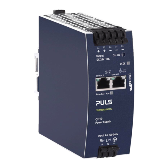
Page 14: Front Side And User Elements
CP10.241-ETC 24 V, 10 A, 240 W, S CP-Series INGLE HASE 13. Front Side and User Elements Fig. 13-1 Front side A Input Terminals Phase (Line) input Neutral conductor input PE (Protective Earth) input Output Terminals Three terminals for the negative and two terminals for the positive pole. -
Page 15: Terminals And Wiring
CP10.241-ETC 24 V, 10 A, 240 W, S CP-Series INGLE HASE 14. Terminals and Wiring The terminals are IP20 Finger safe constructed and suitable for field- and factory wiring. Input Output EtherCAT Connectors Type Spring Terminal Spring Terminal RJ45 Receptable Solid wire max. -
Page 16: Lifetime Expectancy
CP10.241-ETC 24 V, 10 A, 240 W, S CP-Series INGLE HASE 15. Lifetime Expectancy The Lifetime expectancy shown in the table indicates the minimum operating hours (service lifetime) and is determined by the lifetime expectancy of the built-in electrolytic capacitors. Lifetime expectancy is specified in operational hours and is calculated according to the capacitor’s manufacturer specification. -
Page 17: Emc
CP10.241-ETC 24 V, 10 A, 240 W, S CP-Series INGLE HASE 17. EMC The EMC behavior of the device is designed for applications in industrial environment as well as in commercial, light- industrial and residential environments. The device complies with EN IEC 61000-6-1, EN IEC 61000-6-2, EN IEC 61000-6-3, EN IEC 61000-6-8, EN IEC 61000-6-4, EN IEC 61000-3-2 and EN 61000-3-3. - Page 18 CP10.241-ETC 24 V, 10 A, 240 W, S CP-Series INGLE HASE EMC Emission Conducted emission EN 55011, EN 55032, FCC Part 15, CISPR 11, Class B input lines CISPR 32 Conducted emission IEC/CISPR 16-1-2, IEC/CISPR 16-2-1 EN IEC 61000-6-3 Limits for DC power output lines ports fulfilled Conducted emission...
-
Page 19: Environment
CP10.241-ETC 24 V, 10 A, 240 W, S CP-Series INGLE HASE 18. Environment Operational temperature -25 °C to +70 °C The operational temperature is the ambient or surrounding temperature and is defined as the air temperature 2cm below the device. Storage temperature -40 °C to +85 °C For storage and transportation... -
Page 20: Safety And Protection Features
CP10.241-ETC 24 V, 10 A, 240 W, S CP-Series INGLE HASE 19. Safety and Protection Features Insulation resistance min. 500 MOhm At delivered condition between input and output, measured with 500 Vdc min. 500 MOhm At delivered condition between input and PE, measured with 500 Vdc At delivered condition between output and PE, min. -
Page 21: Dielectric Strength
CP10.241-ETC 24 V, 10 A, 240 W, S CP-Series INGLE HASE 20. Dielectric Strength The output voltage is floating and has no ohmic connection to the ground. The output is insulated to the input by a double or reinforced insulation. Type and routine tests are conducted by the manufacturer. -
Page 22: Approved, Fulfilled Or Tested Standards
CP10.241-ETC 24 V, 10 A, 240 W, S CP-Series INGLE HASE 21. Approved, Fulfilled or Tested Standards IEC 61010-2-201 CB Scheme Certificate IEC 61010-2-201 Electrical Equipment for Measurement, Control and Laboratory Use - Particular requirements for control equipment UL 61010-2-201 UL Certificate Listed equipment for category NMTR - Electrical Equipment for Measurement, Control and Laboratory Use - Particular... -
Page 23: Physical Dimensions And Weight
CP10.241-ETC 24 V, 10 A, 240 W, S CP-Series INGLE HASE 23. Physical Dimensions and Weight Width 48 mm Height 124 mm 127 mm Depth The DIN rail depth must be added to the unit depth to calculate the total required installation depth. -
Page 24: Accessories
CP10.241-ETC 24 V, 10 A, 240 W, S CP-Series INGLE HASE 24. Accessories 24.1. ZM10.WALL – Wall/Panel Mounting Bracket This bracket is used to mount the devices on a wall/panel without utilizing the DIN rail. The bracket can be mounted without detaching the DIN rail brackets from the power supply. -
Page 25: Uf20.241 Buffer Module
CP10.241-ETC 24 V, 10 A, 240 W, S CP-Series INGLE HASE 24.2. UF20.241 Buffer Module The UF20.241 buffer module is a supplementary device for DC 24 V power supplies. It delivers power to bridge typical mains failures or extends the hold-up time after the AC power is turned off. -
Page 26: Application Notes
CP10.241-ETC 24 V, 10 A, 240 W, S CP-Series INGLE HASE 25. Application Notes 25.1. Peak Current Capability The unit can deliver peak currents (up to several milliseconds) which are higher than the specified short term currents. This helps to start current demanding loads. Solenoids, contactors and pneumatic modules often have a steady state coil and a pick-up coil. -
Page 27: Output Circuit Breakers
CP10.241-ETC 24 V, 10 A, 240 W, S CP-Series INGLE HASE 25.2. Output Circuit Breakers Standard miniature circuit breakers (MCB’s or UL 1077 circuit breakers) are commonly used for AC-supply systems and may also be used on 24 V branches. MCB’s are designed to protect wires and circuits. -
Page 28: Charging Of Batteries
CP10.241-ETC 24 V, 10 A, 240 W, S CP-Series INGLE HASE 25.3. Charging of Batteries The power supply can be used to charge lead-acid or maintenance-free batteries. Two 12 V SLA or VRLA batteries are needed in series connection. Instructions for charging batteries: Use only matched batteries when putting 12 V types in series. -
Page 29: Parallel Use For Redundancy
CP10.241-ETC 24 V, 10 A, 240 W, S CP-Series INGLE HASE 25.6. Parallel Use for Redundancy 1+1 Redundancy: Devices can be paralleled for redundancy to gain higher system availability. Redundant systems require a certain amount of extra power to support the load in case one device fails. The simplest way is to put two devices in parallel. This is called a 1+1 redundancy. -
Page 30: Operation On Two Phases
CP10.241-ETC 24 V, 10 A, 240 W, S CP-Series INGLE HASE 25.7. Operation on Two Phases The power supply can also be used on two-phases of a three-phase-system. Such a phase-to-phase connection is allowed as long as the supplying voltage is below 240 V +10 % Power Supply Ensure that the wire, which is connected to the N-terminal, is...
Need help?
Do you have a question about the DIMENSION CP Series and is the answer not in the manual?
Questions and answers