Puls DIMENSION CP Series Manual
Single phase input
Hide thumbs
Also See for DIMENSION CP Series:
- Manual (278 pages) ,
- Quick start manual (29 pages) ,
- User manual (28 pages)
Table of Contents
Advertisement
Quick Links
CP-Series
G
D
ENERAL
ESCRIPTION
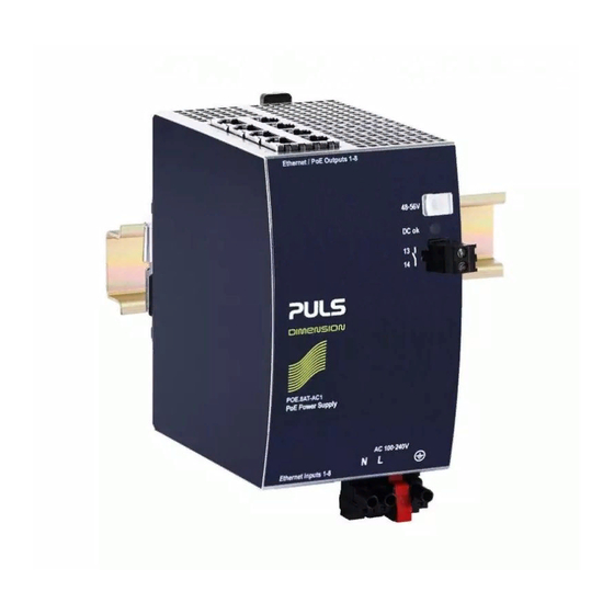
The POE.8AT-AC1 is a DIN-rail mountable single-phase-input
power supply, which provides power for
Power over Ethernet (PoE) applications. It injects
power to 8 individual PoE channels (IEEE 802.3at)
via RJ45 Ethernet ports. The device can supply powered devices
PD of type1 and type2.
O
N
RDER
UMBERS
PoE Power Supply POE.8AT-AC1
Mechanical Accessory
Apr. 2020 / Rev. 0.1a DS-POE.8AT-AC1-EN
All parameters are specified at 48V, 5.4A, 230Vac, 50Hz, 25°C ambient and after a 5 minutes run-in time unless otherwise noted.
PRELIMINARYY
ZM10.WALL
Wall/panel mount bracket
www.pulspower.com Phone +49 89 9278 0 Germany
56V, 8
P
E P
O
OWER SUPPLY
•
AC 100-240V Wide-range input
•
Width only 77mm
•
8x 30W ports (acc.to IEEE 802.3 at)
•
Data transfer rate 1000Mbps
•
Temperature range -25°C and +70°C
•
Plug & Play installation and DIN rail mounting
•
3 Year Warranty
S
-
D
HORT
FORM
ATA
AC Input voltage
AC 100-240V
range
DC Output voltage
48 – 56Vdc
range
Output power
8x 30W
channels
8x 22.5W
Derate linearly between +60°C and +70°C
Output current
0.63A
limitation
0.47A
Efficiency
95.4%
Losses
11.3W
Temperature range
-25°C to +70°C
Size (wxhxd)
77x128x117mm
Weight
900g / 1.98 lb
M
ARKINGS
UL 61010 / planned
POE.8AT-AC1
30W, S
P
I
X
INGLE
HASE
NPUT
Suitable for TN-, TT- and ITIT
mains networks
Factory setting 56V
Below +60°C ambient
At +70°C ambient
Below +60°C ambient
At +70°C ambient
At 230Vac
At 230Vac
Without DIN-Rail
1/19
Advertisement
Table of Contents

Related Manuals for Puls DIMENSION CP Series


Summary of Contents for Puls DIMENSION CP Series
- Page 1 POE.8AT-AC1 PRELIMINARYY 56V, 8 30W, S CP-Series INGLE HASE NPUT OWER SUPPLY • AC 100-240V Wide-range input • Width only 77mm • 8x 30W ports (acc.to IEEE 802.3 at) • Data transfer rate 1000Mbps • Temperature range -25°C and +70°C •...
-
Page 2: Table Of Contents
POE.8AT-AC1 PRELIMINARYY 56V, 8 30W, S CP-Series INGLE HASE NPUT NDEX Page Page Intended Use ..............3 16. Protection Features ........... 13 Installation Requirements ..........3 17. Safety Features ............13 AC-Input ............... 4 18. Dielectric Strength ............. 14 DC-Input ............... 5 19. -
Page 3: Intended Use
POE.8AT-AC1 PRELIMINARYY 56V, 8 30W, S CP-Series INGLE HASE NPUT 1. I NTENDED This device is designed for installation in an enclosure and is intended for commercial use, such as in industrial control, process control, monitoring and measurement equipment or the like. Do not use this device in equipment where malfunction may cause severe personal injury or threaten human life. -
Page 4: Ac-Input
POE.8AT-AC1 PRELIMINARYY 56V, 8 30W, S CP-Series INGLE HASE NPUT 3. AC-I NPUT AC input Nom. AC 100-240V Suitable for TN-, TT- and IT mains networks Allowed voltage L or N to earth Max. 300Vac Continuous according to IEC 62477-1 Input frequency Nom. -
Page 5: Dc-Input
POE.8AT-AC1 PRELIMINARYY 56V, 8 30W, S CP-Series INGLE HASE NPUT Fig. 3-5 Derating requirements Allowed Output C urrent at 48V 5.4A A... below 60°C ambient temperature B ... below 55°C ambient temperature C ... below 45°C ambient temperature 264Vdc DC Input Voltage 4. -
Page 6: Input Inrush Current
POE.8AT-AC1 PRELIMINARYY 56V, 8 30W, S CP-Series INGLE HASE NPUT 5. I NPUT NRUSH URRENT An active inrush limitation circuit (NTCs, which are bypassed by a relay contact) limits the input inrush current after turn-on of the input voltage. The charging current into EMI suppression capacitors is disregarded in the first microseconds after switch-on. AC 100V AC 120V AC 230V... -
Page 7: Hold-Up Time
POE.8AT-AC1 PRELIMINARYY 56V, 8 30W, S CP-Series INGLE HASE NPUT 7. H AC 100V AC 120V AC 230V Hold-up Time Min. 50ms 50ms 50ms At 48V, 2.7A, see Fig. 7-1 Min. 26ms 26ms 26ms At 48V, 5.4A, see Fig. 7-1 Fig. -
Page 8: Efficiency And Power Losses
POE.8AT-AC1 PRELIMINARYY 56V, 8 30W, S CP-Series INGLE HASE NPUT 9. E FFICIENCY AND OWER OSSES AC 100V AC 120V AC 230V Efficiency Typ. 94.3% 94.6% 95.4% at 8x 80W output Power losses Typ. 10.2W 9.5W 7.4W at 8x 80W output 10. -
Page 9: Functional Diagram
POE.8AT-AC1 PRELIMINARYY 56V, 8 30W, S CP-Series INGLE HASE NPUT 11. F UNCTIONAL IAGRAM Fig. 11-1 Functional diagram 12. T ERMINALS AND IRING The terminals are IP20 finger safe constructed and suitable for field- and factory wiring. Input DC-OK-Signal Type Hot swap connector Push-in terminals Max. -
Page 10: Front Side And User Elements
POE.8AT-AC1 PRELIMINARYY 56V, 8 30W, S CP-Series INGLE HASE NPUT Ferrules are allowed. 13. F RONT IDE AND LEMENTS Fig. 13-1 Front side Power input terminal Hot swap connector Ethernet input RJ45 jacks Power-over-Ethernet output RJ45 jacks Output voltage Factory setting 56V potentiometer DC-OK LED (green) ON when the output voltage... -
Page 11: 14. Emc
POE.8AT-AC1 PRELIMINARYY 56V, 8 30W, S CP-Series INGLE HASE NPUT 14. EMC The power supply is suitable for applications in industrial environment as well as in residential, commercial and light industry environments. EMC Immunity According to generic standards: EN 61000-6-1 and EN 61000-6-2 Electrostatic discharge EN 61000-4-2 Contact discharge... -
Page 12: Environment
POE.8AT-AC1 PRELIMINARYY 56V, 8 30W, S CP-Series INGLE HASE NPUT Switching Frequencies PFC converter 110kHz Fixed frequency Main converter 84kHz to 140kHz Output load dependent Auxiliary converter 60kHz Fixed frequency 15. E NVIRONMENT Operational temperature -25°C to +70°C (-13°F to 158°F) Reduce output power according to Fig. -
Page 13: Protection Features
POE.8AT-AC1 PRELIMINARYY 56V, 8 30W, S CP-Series INGLE HASE NPUT 16. P ROTECTION EATURES Output protection Electronically protected against overload, no-load and short-circuits. In case of a protection event, audible noise may occur. Output over-voltage protection Typ. 58.5Vdc In case of an internal power supply defect, a redundant circuit Max. -
Page 14: Dielectric Strength
POE.8AT-AC1 PRELIMINARYY 56V, 8 30W, S CP-Series INGLE HASE NPUT 18. D IELECTRIC TRENGTH The output voltage is floating and has no ohmic connection to the ground. Type and factory tests are conducted by the manufacturer. Field tests may be conducted in the field using the appropriate test equipment which applies the voltage with a slow ramp (2s up and 2s down). -
Page 15: Approvals
POE.8AT-AC1 PRELIMINARYY 56V, 8 30W, S CP-Series INGLE HASE NPUT 19. A PPROVALS The CE mark indicates conformance with the EC Declaration of Conformity - EMC directive, - Low-voltage directive (LVD) Listed as Open Type Device for use in Control Equipment UL 61010 UL Category NMTR, NMTR7 (planned) -
Page 16: Physical Dimensions And Weight
POE.8AT-AC1 PRELIMINARYY 56V, 8 30W, S CP-Series INGLE HASE NPUT 21. P HYSICAL IMENSIONS AND EIGHT Width 77mm 3,03” 128mm 5,06” Depth 117mm 4.61’’ The DIN-rail height must be added to the unit depth to calculate the total required installation depth. Weight 900g / 1.98lb DIN-Rail... -
Page 17: Accessories
POE.8AT-AC1 PRELIMINARYY 56V, 8 30W, S CP-Series INGLE HASE NPUT 22. A CCESSORIES 22.1. ZM10.WALL – W ANEL OUNT RACKET This bracket is used to mount the devices on a wall/panel without utilizing a DIN-Rail. The bracket can be mounted without detaching the DIN-rail brackets. -
Page 18: Application Notes
POE.8AT-AC1 PRELIMINARYY 56V, 8 30W, S CP-Series INGLE HASE NPUT 23. A PPLICATION OTES 23.1. E XTERNAL NPUT ROTECTION The unit is tested and approved for branch circuits up to 30A (UL) and 32A (IEC). An external protection is only required if the supplying branch has an ampacity greater than this. -
Page 19: Mounting Orientations
POE.8AT-AC1 PRELIMINARYY 56V, 8 30W, S CP-Series INGLE HASE NPUT 23.4. M OUNTING RIENTATIONS Mounting orientations other than all terminals on the bottom require a reduction in continuous output power or a limitation in the maximum allowed ambient temperature. The amount of reduction influences the lifetime expectancy of the power supply. Therefore, two different derating curves for continuous operation can be found below: Curve A1 Recommended output current.
Need help?
Do you have a question about the DIMENSION CP Series and is the answer not in the manual?
Questions and answers