Omron CJ2 CPU UNIT User Manual
Cj2 cpu unit hardware
Hide thumbs
Also See for CJ2 CPU UNIT:
- User manual (670 pages) ,
- Connection manual (68 pages) ,
- Manual (40 pages)

Subscribe to Our Youtube Channel
Related Manuals for Omron CJ2 CPU UNIT


Summary of Contents for Omron CJ2 CPU UNIT
- Page 1 Cat. No. W472-E1-07 SYSMAC CJ Series CJ2H-CPU6@-EIP CJ2H-CPU6@ CJ2M-CPU@@ CJ2 CPU Unit Hardware USER’S MANUAL...
- Page 3 OMRON. No patent liability is assumed with respect to the use of the information contained herein. Moreover, because OMRON is con- stantly striving to improve its high-quality products, the information contained in this manual is subject to change without notice.
- Page 5 SYSMAC CJ Series CJ2H-CPU6@-EIP CJ2H-CPU6@ CJ2M-CPU@@ CJ2 CPU Unit Hardware User’s Manual Revised July 2010...
-
Page 7: Intended Audience
NSJ-series Expansion Units CJ-series Basic I/O Units CS-series Power Supply Units CJ-series Special I/O Units Note: A special Power Supply Unit must be used for CS1D CPU Units. CJ-series CPU Bus Units CJ-series Power Supply Units CJ2 CPU Unit Hardware User’s Manual... - Page 8 • Settings Debugging Operation • Checking I/O wiring, setting the Auxiliary Area settings, and Maintenance performing trial operation • Monitoring and debugging with the CX-Programmer Troubleshooting Error codes and remedies if a problem occurs CJ2 CPU Unit Hardware User’s Manual...
- Page 9 This section describes functions that are built into the CPU Unit. Section 11 Programming Devices This section describes the procedure for connecting the CJ2 CPU Unit to the CX-Pro- and Communications grammer or other Support Software and to other devices.
- Page 10 Section 9 PWM Outputs This section describes the variable-duty-factor (PWM) outputs. The appendices provide a table of flag changes for pulse outputs, a comparison table Appendices with other models, and a performance table. CJ2 CPU Unit Hardware User’s Manual...
-
Page 11: Additional Information
If the locking tabs are not secured properly, the connectors may become loose and not function properly. Be sure to slide the locking tabs until they are securely in place. Manual name CJ2 CPU Unit Hardware User’s Manual 5-13 This illustration is provided only as a sample and may not literally appear in this manual. - Page 12 CJ2 CPU Unit Hardware User’s Manual...
- Page 13 Sections in this Manual Overview Basic System Configuration and Devices Nomenclature and Functions Support Software Installation Troubleshooting Inspection and Maintenance Backup Operations Appendices CJ2 CPU Unit Hardware User’s Manual...
- Page 14 CJ2 CPU Unit Hardware User’s Manual...
-
Page 15: Table Of Contents
CONTENTS Introduction....................... 1 CJ2 CPU Unit Manuals ..................... 2 Manual Structure ...................... 5 Sections in this Manual.................... 7 Safety Precautions ....................17 Application Precautions..................21 Operating Environment Precautions ..............26 Regulations and Standards ................... 27 Unit Versions of CJ2 CPU Units ................29 Related Manuals ..................... -
Page 16: Table Of Contents
Connecting to Connector-Terminal Block Conversion Units or I/O Relay Terminals ....5-33 5-3-5 Connecting Pulse I/O Modules to External I/O Devices (CJ2M CPU Unit Only)....... 5-33 5-3-6 Connecting I/O Devices ......................5-35 5-3-7 Connecting through an Ethernet Cable (CJ2H-CPU6 -EIP and CJ2M-CPU3 Only).... 5-39 CJ2 CPU Unit Hardware User’s Manual... -
Page 17: Table Of Contents
8-3-2 Operating Procedures......................... 8-8 8-3-3 Verifying Backup Operations with Indicators ................8-10 8-3-4 Related Auxiliary Bits/Words ....................8-12 8-3-5 Time Required for Simple Backup .................... 8-12 8-3-6 Data Backed Up Using Simple Backup..................8-12 CJ2 CPU Unit Hardware User’s Manual... -
Page 18: Table Of Contents
Load Short-circuit Protection for CJ1W-OD204/OD212/OD232/MD232 .........A-151 A-7 Relay Output Noise Reduction Methods ................A-153 A-8 Functions Supported for Unit Versions................A-155 A-8-1 CJ2H CPU Units ........................A-155 A-8-2 CJ2M CPU Units ........................A-156 Index ........................ Index-1 Revision History ..................Revision-1 CJ2 CPU Unit Hardware User’s Manual... - Page 19 WHETHER SUCH CLAIM IS BASED ON CONTRACT, WARRANTY, NEGLIGENCE, OR STRICT LIABILITY. In no event shall the responsibility of OMRON for any act exceed the individual price of the product on which liability is asserted. IN NO EVENT SHALL OMRON BE RESPONSIBLE FOR WARRANTY, REPAIR, OR OTHER CLAIMS...
- Page 20 Application Considerations SUITABILITY FOR USE OMRON shall not be responsible for conformity with any standards, codes, or regulations that apply to the combination of products in the customer's application or use of the products. At the customer's request, OMRON will provide applicable third party certification documents identifying ratings and limitations of use that apply to the products.
- Page 21 Performance data given in this manual is provided as a guide for the user in determining suitability and does not constitute a warranty. It may represent the result of OMRON's test conditions, and the users must correlate it to actual application requirements. Actual performance is subject to the OMRON Warranty and Limitations of Liability.
- Page 22 CJ2 CPU Unit Hardware User’s Manual...
-
Page 23: Safety Precautions
Indicates precautions on what to do and what not to do to ensure using the product safely. Precautions for Correct Use Indicates precautions on what to do and what not to do to ensure proper operation and performance. CJ2 CPU Unit Hardware User’s Manual... - Page 24 This example indicates a general precaution. The triangle symbol indicates precautions (including warnings). The specific operation is shown in the triangle and explained in text. This example indicates a precaution for hot surfaces. CJ2 CPU Unit Hardware User’s Manual...
- Page 25 Fail-safe measures must be taken by the customer to ensure safety in the event of incorrect, missing, or abnormal signals caused by broken signal lines, momentary power interruptions, or other causes. Serious accidents may result from abnormal operation if proper measures are not provided. CJ2 CPU Unit Hardware User’s Manual...
- Page 26 Never ground the 24 V side, as shown below. Wiring in Which the 24-V Power Supply Will Short Non-insulated DC power supply 24 V Peripheral cable Peripheral device (e.g., Power Supply CPU Unit personal computer) Unit CJ2 CPU Unit Hardware User’s Manual...
-
Page 27: Application Precautions
• Do not install the PLC near sources of strong high-frequency noise. • Before touching a Unit, be sure to first touch a grounded metallic object in order to discharge any static build-up. Not doing so may result in malfunction or damage. CJ2 CPU Unit Hardware User’s Manual... - Page 28 • Confirm that no adverse effect will occur in the system before attempting any of the following. Not doing so may result in an unexpected operation. • Changing the operating mode of the PLC (including the setting of the startup operating mode). • Force-setting/force-resetting any bit in memory. CJ2 CPU Unit Hardware User’s Manual...
- Page 29 • If there is interference with network communications, output status will depend on the devices that are being used. When using devices with outputs, confirm the operation that will occur when there is interference with communications, and implement safety measures as required. CJ2 CPU Unit Hardware User’s Manual...
- Page 30 If an indirect specification causes the address to exceed the area of the start address, the system will access data in other area, and unexpected operation may occur. CJ2 CPU Unit Hardware User’s Manual...
- Page 31 DC Output Units and other Units will momentarily turn ON when power is turned ON to the PLC. • Install external breakers and take other safety measures against short-circuiting in external wiring. Insufficient safety measures against short-circuiting may result in burning. CJ2 CPU Unit Hardware User’s Manual...
- Page 32 • Locations subject to static electricity or other forms of noise. • Locations subject to strong electromagnetic fields. • Locations subject to possible exposure to radioactivity. • Locations close to power supplies. CJ2 CPU Unit Hardware User’s Manual...
- Page 33 Concepts EMC Directives OMRON devices that comply with EC Directives also conform to the related EMC standards so that they can be more easily built into other devices or the overall machine. The actual products have been checked for conformity to EMC standards (see the following note). Whether the products con- form to the standards in the system used by the customer, however, must be checked by the cus- tomer.
- Page 34 It may not be possible to use the product in some loca- tions. Contact your OMRON representative before attempting to use a PLC on a ship. Usage Conditions for NK and LR Shipbuilding Standards Usage Conditions for Applications Other Than on the Bridge or Deck •...
- Page 35 • If you don't know the device type and CPU type, but are connected directly to the CPU Unit on a serial line, select PLC - Auto Online to go online, and then select PLC - Edit - Information from the menus. CJ2 CPU Unit Hardware User’s Manual...
- Page 36 In either case, the following PLC Information Dialog Box will be displayed. Unit version Use the above display to confirm the unit version of the CPU Unit. Unit Manufacturing Information In the IO Table Window, right-click and select Unit Manufacturing information - CPU Unit. CJ2 CPU Unit Hardware User’s Manual...
- Page 37 The following unit version labels are provided with the CPU Unit. Ver. 1.0 Ver. 1.0 These labels can be attached to the front of previous CPU Units to differentiate between CPU Units of different unit versions. CJ2 CPU Unit Hardware User’s Manual...
- Page 38 Unit version 1.2 Unit version 1.3 CJ2M CPU Unit CJ2M-CPU3@ Unit version 1.0 (Built-in EtherNet/IP section: Unit version 2.0) Unit version 2.0 (Built-in EtherNet/IP section: Unit version 2.0) CJ2M-CPU1@ Unit version 1.0 Unit version 2.0 CJ2 CPU Unit Hardware User’s Manual...
- Page 39 MONITOR mode, however, are also supported by CX-Programmer version 8.02. *3 A Programming Console cannot be used with a CJ2 CPU Unit. Pull-down List for PLC Models Unit versions are not differentiated in the pull-down list for PLC models in the Change PLC Dialog Box of the CX-Programmer.
- Page 40 New instructions cannot be PLC to the CX-Programmer. a program containing instruc- uploaded to lower versions of tions supported only by higher CX-Programmer. Use a higher versions of CX-Programmer to a version of CX-Programmer. lower version. CJ2 CPU Unit Hardware User’s Manual...
-
Page 41: Basic System Configuration
Related Manuals Manuals related to a PLC built using a CJ-series CJ2 CPU Unit are listed in the following table. Use these manuals for reference. Manual Cat. No. Model Application Description CJ-series CJ2 CPU W472 CJ2H-CPU6@-EIP Hardware specifications for Describes the following for CJ2 CPU Units:... - Page 42 Instructions Reference Manual (W474). grammer version 6.1 or higher CS/CJ/CP/NSJ- W464 CXONE-AL@@C-V@/ Network setup and moni- Describes the operating procedures for the CX- series CX-Integrator CXONE-AL@@D-V@ toring Integrator. Network Configura- tion Software Opera- tion Manual CJ2 CPU Unit Hardware User’s Manual...
- Page 43 CJ2 CPU Unit Features ........
-
Page 44: Overview Of Cj2 Cpu Units
More Serial Communications Ports (CJ2M-CPU3@ Only) With the standard CJ2M CPU Unit (CJ2M-CPU3@) you can add an RS-232C or RS-422A/485 Option Board to the standard-feature EtherNet/IP port to increase the number of serial communica- tions ports. CJ2 CPU Unit Hardware User’s Manual... - Page 45 Improved debugging Easier programming Easier programming Tag access Built-in EtherNet/IP port General-purpose networks for Support Software interface Optional serial communications ports Expandable Expandable General-purpose pulse I/O pulse I/O networks for Support Software interface RS-232C RS-422A/485 CJ2 CPU Unit Hardware User’s Manual...
-
Page 46: Cj2 Cpu Unit Features
Example: For I/O interrupt tasks, the time for normal operation is 37 µs but the time is 25 µs if High-speed interrupt function is used. • Minimum interval setting of 0.1 ms for one of Scheduled Interrupt Tasks (For unit version 1.0, the minimum interval is 0.2 ms.) CJ2 CPU Unit Hardware User’s Manual... - Page 47 Prevent Connecting to the Wrong PLC by Using PLC Names from Support Software A user-set PLC name can be recorded in a CJ2 CPU Unit. When using Support Software to connect online to a PLC, verification of the PLC name prevents incorrect connections from the Support Soft- ware.
- Page 48 COMM BKUP Tags are allocated in OPEN a high-capacity area. MCPWR BUSY Specified by tag a. PERIP HERAL Designing is performed by using only tags, PORT with no need to pay attention to addresses. CJ2 CPU Unit Hardware User’s Manual...
- Page 49 Synchronous Unit Operation (CJ2H CPU Units with Unit Version 1.1 or Later) A CJ2 CPU Unit can synchronize the start of the processing performed by CPU Bus Units and Special I/O Units to a specified cycle. Synchronous data refreshing can be used between the CJ2H CPU Unit and Synchronous Units,* and the refreshed data can be used in operations in a synchronous interrupt task.
- Page 50 Ladder diagram FB in ladder diagram The programming language suited to the process can FB in ST program be used. a := a + 1; FB_(A:=B,C=>D); Transition and action programs in SFC CJ2 CPU Unit Hardware User’s Manual...
- Page 51 With CX-Programmer version 8.3 or higher, a parameter can be set to enable force-setting/resetting bits in specified EM Area banks. (This function is supported only by CJ2H CPU Units with unit ver- sion 1.2 or later and CJ2M CPU Units.) CJ2 CPU Unit Hardware User’s Manual...
- Page 52 (isolated, max. transmis- COMM sion distance: 500 m) sion distance: 50 m) EtherNet/IP RS-232C Barcode reader or other general-purpose component Or RS-422A/485 Example: Serial PLC Links CJ2M, CP1E, CP1L or CJ1M 1-10 CJ2 CPU Unit Hardware User’s Manual...
- Page 53 • Interrupt inputs: 8 (4 per Pulse I/O Module) • Variable duty factor pulse outputs: 4 (2 per Pulse I/O Module) • High-speed counter inputs: 4 (2 per Pulse I/O Module) • Quick-response inputs: 8 (4 per Pulse I/O Module) CJ2 CPU Unit Hardware User’s Manual 1-11...
-
Page 54: Basic Operating Procedure
• DM Area Settings for Special I/O Units and CPU Bus Units: Refer to Section 8 I/O Allocations and Unit Settings in the CJ2 CPU Unit Software User’s Manual (Cat. No. W473). • PLC Setup: Refer to Section 9 PLC Setup in the CJ2 CPU Unit Software User’s Manual (Cat. No. W473). -
Page 55: Specifications
, 3 times in X, Y, and Z directions (100 m/s for Relay Output Units) Battery Life 5 years at 25°C Model CJ1W-BAT01 Applicable Standards Conforms to cULus, NK, LR, and EC Directives. * Without a Serial Option Board CJ2 CPU Unit Hardware User’s Manual 1-13... -
Page 56: Performance Specifications
10 µs × Number of Pulse I/O Modules *2 This applies when high-speed interrupts are used. *3 Supported only by CJ2M CPU Units with unit version 2.0 or later. A Pulse I/O Module must be mounted. 1-14 CJ2 CPU Unit Hardware User’s Manual... -
Page 57: Index
EM Area force-set/reset function. With CJ2M CPU Units, force-setting/resetting bits in the EM Area is possible only for banks specified for the EM Area force-set/reset function. CJ2 CPU Unit Hardware User’s Manual 1-15... - Page 58 *8 Supported only by the CJ2H-CPU6@-EIP and CJ2M-CPU3@. *9 This data type cannot be used in Function blocks. *10 This data type can be used only in Function blocks. *11 Supported only when CX-Programmer version 9.0 or higher is used. 1-16 CJ2 CPU Unit Hardware User’s Manual...
- Page 59 −32,768 to +32,767 ms Delay Value File Memory Memory Card (128, 256, or 512 Mbytes) (Use the Memory Cards provided by OMRON.) EM file memory (Part of the EM Area can be converted for use as file memory.) Source/Com- Program source, comments, program Capacity: 3.5 Mbytes...
- Page 60 8 (Seven tags if PLC status is included in the segment.) *12 The EtherNet/IP port is built into the CJ2H-CPU6@-EIP and CJ2M-CPU3@ only. *13 “Packets per second” is the number of communications packets that can be processed per second. 1-18 CJ2 CPU Unit Hardware User’s Manual...
- Page 61 *17 The EtherNet/IP port supports an IGMP client, so unnecessary multicast packets are filtered by using an Ethernet switch that supports IGMP snooping. CJ2 CPU Unit Hardware User’s Manual 1-19...
- Page 62 4 max. (2 per Pulse I/O Module) Output frequency: 0.1 to 6,553.5 Hz (in 0.1-Hz increments) or 1 to 32,800 Hz (in 1-Hz incre- ments) Duty ratio: 0.0% to 100.0% (in 0.1% incre- ments) 1-20 CJ2 CPU Unit Hardware User’s Manual...
-
Page 63: Function Specifications
The first words allocated to a Units on the Racks can be set. *1 Supported only by CJ2H CPU Units with unit version 1.1 or later and CJ2M CPU Units. *2 Supported only by CJ2H CPU Units with unit version 1.1 or later. CJ2 CPU Unit Hardware User’s Manual 1-21... - Page 64 CSV/TXT format. Data in CSV/TXT format in the Memory Card can be read to I/O memory in the CPU Unit. *3 Supported only by CJ2M CPU Unit with unit version 2.0 or later. A Pulse I/O Module must be mounted. 1-22 CJ2 CPU Unit Hardware User’s Manual...
- Page 65 *4 A Serial Option Board is required to use a serial port for the CJ2M-CPU3@ CPU Unit. *5 A Serial Option Board is required to use the CJ2M-CPU3@ CPU Unit in Serial PLC Links. *6 Supported only by CJ2H-CPU6@-EIP and CJ2M-CPU3@. CJ2 CPU Unit Hardware User’s Manual 1-23...
- Page 66 *7 Supported only by the CJ2M CPU Units. *8 Pulse I/O Modules are supported only by CJ2M CPU Units with unit version 2.0 or later. *9 Supported only by CJ2H CPU Units with unit version 1.1 or later. 1-24 CJ2 CPU Unit Hardware User’s Manual...
- Page 67 I/O Units and CPU Bus Units have not been recognized at the startup in RUN or MONITOR mode. *10 Supported only by CJ2H CPU Units with unit version 1.2 or later and CJ2M CPU Units. CJ2 CPU Unit Hardware User’s Manual 1-25...
- Page 68 I/O tables does not agree with the actual number of Units that are connected or an Interrupt Unit has been connected in the wrong position. *11 Supported only by CJ2H-CPU6@-EIP and CJ2M-CPU3@. *12 Supported only by the CJ2M-CPU3@. 1-26 CJ2 CPU Unit Hardware User’s Manual...
- Page 69 Hardware ID Using Lot Numbers This function sets operation protection by identifying hardware using the user programs according to lot numbers stored in the Auxiliary Area. *13 This function can be used only with CJ2H CPU Units. CJ2 CPU Unit Hardware User’s Manual 1-27...
- Page 70 1 Overview 1-28 CJ2 CPU Unit Hardware User’s Manual...
-
Page 71: Expanded System Configuration
Communications Networks ........2-29 CJ2 CPU Unit Hardware User’s Manual... - Page 72 A Memory Card is optional. * All CJ-series Units can be used as Configuration Units, but only Units that specifically support the CJ2 CPU Unit can access the expanded portions of the I/O memory areas of the CJ2 CPU Units (i.e., A960 to A1471, A10000 to A11535, and EM banks D to 18).
- Page 73 2 Basic System Configuration and Devices 2-1-2 CPU Rack The CPU Rack consists of a CJ2 CPU Unit, a CJ-series Power Supply Unit, CJ-series Configuration Units, and a CJ-series End Cover. Up to 10 Configuration Units can be connected. CJ2H CPU Units...
- Page 74 Bus Units Must be connected to the right end of the CPU Rack. One End Cover Cover is provided with the CPU Unit. A fatal error will occur if the End Cover is not connected. CJ2 CPU Unit Hardware User’s Manual...
- Page 75 *1 Increases by 0.15 A/Unit when an NT-AL001 Link Adapter is used. Increases by 0.04 A/Unit when a CJ1W-CIF11 RS-422A Converter is used. Increases by 0.20 A/Unit when an NV3W-M@20L Programmable Terminal is used. *2 Includes the weight of the End Cover. CJ2 CPU Unit Hardware User’s Manual...
- Page 76 Increases by 0.04 A/Unit when a CJ1W-CIF11 RS-422A Converter is used. Increases by 0.20 A/Unit when an NV3W-M@20L Programmable Terminal is used. *2 Includes the weight of the End Cover. *3 The weight of a Serial Option Board is not included. CJ2 CPU Unit Hardware User’s Manual...
- Page 77 100 to 240 VAC 2.8 A 0.4 A 200 g max. CJ1W-PD025 24 VDC 5.0 A 0.8 A 335 g max. CJ1W-PD022 24 VDC (non- 2.0 A 0.4 A 130 g max. insulated type) CJ2 CPU Unit Hardware User’s Manual...
-
Page 78: Memory Cards
End Cover is not connected to CPU Unit and I/O Interface Unit. the right end of the Rack.) *1 One End Cover is provided with the CPU Unit and with an I/O Interface Unit. CJ2 CPU Unit Hardware User’s Manual... - Page 79 Cable length: 1.5 m XW2Z-200K Cable length: 2 m XW2Z-300K Cable length: 3 m XW2Z-500K Cable length: 5 m Servo Relay Units XW2B-20J6-8A To connect one axis XW2B-20J6-9A To connect two axes * CJ2H-CPU6@-EIP or CJ2M-CPU3@ only. CJ2 CPU Unit Hardware User’s Manual...
- Page 80 • CX-Programmer • CX-Integrator • SwitchBox Utility • CX-Simulator • CX-Protocol • CX-Designer • CX-Thermo • CX-Position • CX-Motion/CX-Motion-NCF/CX-Motion-MCH • CX-Drive • CX-Process Tool • NS Faceplate Auto-Builder • CX-FLnet • Network Configurator 2-10 CJ2 CPU Unit Hardware User’s Manual...
-
Page 81: Expansion Racks
CJ-series CPU Rack plus 3 Racks The total length of I/O Connecting Cable CJ-series Expansion Racks between the CPU Rack and an Expansion Rack, and between all Expansion Racks, must be no more than 12 m. CJ2 CPU Unit Hardware User’s Manual 2-11... - Page 82 CJ1W-II101 One Interface Unit is required for each CJ-series Expan- 0.13 A 130 g sion Rack. One End Cover is provided with each Unit. max. *1 Includes the weight of the End Cover. 2-12 CJ2 CPU Unit Hardware User’s Manual...
- Page 83 An I/O Connecting Cable connects an I/O Control Unit (CJ1W-IC101) to an 0.3 m I/O Interface Unit (CJ1W-II101), or connects an I/O Interface Unit to CS1W-CN713 0.7 m another I/O Interface Unit. CS1W-CN223 CS1W-CN323 CS1W-CN523 CS1W-CN133 10 m CS1W-CN133B2 12 m CJ2 CPU Unit Hardware User’s Manual 2-13...
- Page 84 Maximum Number of Units A maximum of 10 Units can be connected to the CPU Rack for a CJ2 CPU Unit or to an Expansion Rack. There are no restrictions in the number of each model of Unit based on location.
- Page 85 *3 The cable-side connector is not provided with Units equipped with cables. Purchase the connector separately (Refer to 5-3-3 Wiring Basic I/O Units with Connectors.), or use an OMRON Connector- Terminal Block Con- version Unit or I/O Terminal (Refer to 5-3-4 Connecting to Connector-Terminal Block Conversion Units or I/O Relay Terminals.).
- Page 86 *3 The cable-side connector is not provided with Units equipped with cables. Purchase the connector separately (Refer to 5-3-3 Wiring Basic I/O Units with Connectors.), or use an OMRON Connector- Terminal Block Con- version Unit or I/O Terminal (Refer to 5-3-4 Connecting to Connector-Terminal Block Conversion Units or I/O Relay Terminals.).
- Page 87 *1 The cable-side connector is not provided with Units equipped with cables. Purchase the connector separately (Refer to 5-3-3 Wiring Basic I/O Units with Connectors.), or use an OMRON Connector- Terminal Block Con- version Unit or I/O Terminal (Refer to 5-3-4 Connecting to Connector-Terminal Block Conversion Units or I/O Relay Terminals.).
- Page 88 2 unit numbers) 2 control loops, ther- CJ1W-TC004 20 words 200 words 0 to 94 0.25 150 g max. mocouple inputs, PNP (uses Units outputs, heater burn- words for out detection 2 unit numbers) 2-18 CJ2 CPU Unit Hardware User’s Manual...
- Page 89 2 unit numbers) CJ1W- None 0 to 94 0.31 220 g max. 18 words *1*2 (uses Units/ NC434 words for Rack 2 unit numbers) CJ1W-SP001 None None 50 g max. Space Unit CJ2 CPU Unit Hardware User’s Manual 2-19...
- Page 90 Slaves maximum With a CJ2 CPU Unit, up to 10 Configuration Units can be connected in the CPU Rack and in each Expansion Rack. The CJ1W-NC@@4, however, must be counted as two Units. Configure the Units to satisfy the following formula.
- Page 91 One CF card type I/II CJ1W-SPU01- Not used. 0 to F 0.56 180 g max. 16 Units Unit (High- slot (used with OMRON speed Storage HMC-EF@@@ Memory and Processing Card), one Ethernet Unit) port CJ2 CPU Unit Hardware User’s Manual 2-21...
- Page 92 *9 When mounting to a CJ-series CPU Rack or a CJ-series Expansion Rack, one of these Units uses the space of three Units. *10 Use version 2 or higher of the SYSMAC SPU Unit with a CJ2 CPU Unit. 2-1-5...
- Page 93 0.130 A + 0.080 A × 2 + Current consump- Calculation 0.140 A × 8 tion Result 1.41 A (≤5.0 A) 1.41 A × 5 V = 7.05 W Power consump- Calculation tion Result 7.05 W (≤25 W) CJ2 CPU Unit Hardware User’s Manual 2-23...
- Page 94 Rack Current Consumption and Width Display To display the current consumption and width of Units connected in the CPU Rack or Expansion Rack, select Current Consumption and Width from the Options Menu in the CJ2 CPU Unit I/O Table Window.
- Page 95 Rated input voltage × Input current × Number of input points • Output Units Residual voltage × Maximum load current × Number of output points Note For the CJ Series, calculate the residual voltage at 0.1 V. CJ2 CPU Unit Hardware User’s Manual 2-25...
- Page 96 W_IO_ONOFF = 24 V × 0.0041 A x 128 points + 0.1 × 0.3 A × 128 points = 16.43 W Average Power Consumption (W) W = W_PLC + W_IO_ONOFF = 34.29 W 2-26 CJ2 CPU Unit Hardware User’s Manual...
-
Page 97: Expanded System Configuration
2-2-1 Serial Communications This expanded system can be connected via the CJ2 CPU Unit's built-in serial communications port or a Serial Communications Unit. Various protocols, including Host Link and NT Link, can be used with the serial communications port. A particular protocol can be supported by switching the mode of the serial communications port. -
Page 98: System Configuration Example
For details on the protocol modes that can be selected for each port, refer to 11-2-1 Overview of Serial Communications in the CJ2 CPU Unit Software User’s Manual (Cat. No. W473). Additional Information Use the Peripheral Bus to connect the CJ2 CPU Unit to the CX-Programmer via serial communi- cations. 2-28... -
Page 99: Communications Networks
The CJ Series supports the following communications networks. Select the appropriate network according to the applications. For details on communications networks, refer to 11-3 Communications Networks in the CJ2 CPU Unit Software User’s Manual (Cat. No. W473). EtherNet/IP, Ethernet Connect via the built-in... - Page 100 Large-capacity remote I/O (fixed DeviceNet Master Unit and devices (Slaves). or free allocation) in an open net- Configurator work CompoNet High-speed, multi-point, multi- CompoNet Master Unit node remote I/O in an open net- work 2-30 CJ2 CPU Unit Hardware User’s Manual...
- Page 101 System Configuration ......... . 3-32 CJ2 CPU Unit Hardware User’s Manual...
-
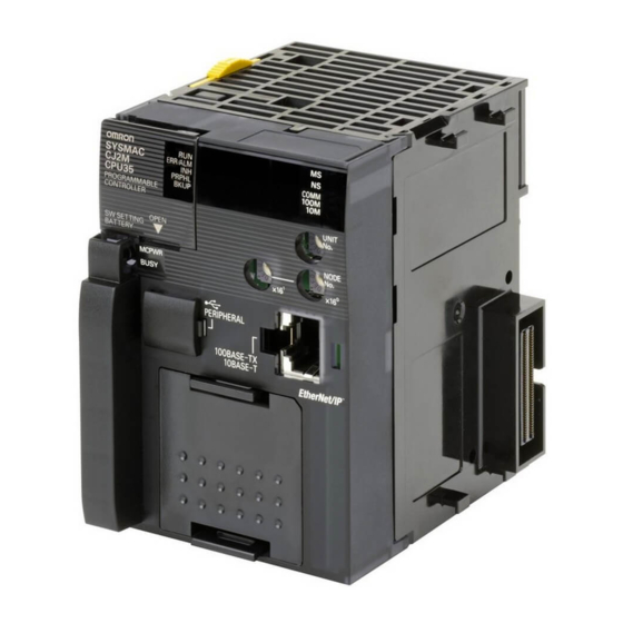
Page 102: Cpu Units
100M COMM BKUP BKUP OPEN OPEN MCPWR BUSY MCPWR BUSY PER IPHE RAL PER IPHE RAL PORT PORT CJ2M-CPU3@ CJ2M-CPU1@ Inside the battery compartment CP1W-CIF01 CP1W-CIF11 or CP1W-CIF12 RS-232C RS-422A/485 Option Board Option Board CJ2 CPU Unit Hardware User’s Manual... -
Page 103: Nomenclature And Functions
13. Serial Option Boards (CJ2M-CPU3@ Only) An Option Board can be connected to the slot. • CP1W-CIF01 RS-232C Option Board • RS-422A/485 Option Board (CP1W-CIF11 (Maximum transmission distance: 50 m) or CP1W-CIF12 (Maximum transmission distance: 500 m)) CJ2 CPU Unit Hardware User’s Manual... - Page 104 (Refer to 3-1-2 Built-in EtherNet/IP Section.) (CJ2H-CPU6@-EIP and CJ2M-CPU3@ only.) The CJ2 CPU Unit status can be checked with the indicators at the top of the front panel of the Unit. The following table describes these indicators. Indicator Color Status...
- Page 105 3 Nomenclature and Functions Memory Card Indicators The status of a Memory Card mounted in the CJ2 CPU Unit can be checked with the indicators in the middle of the front panel of the Unit. The following table describes these indicators.
- Page 106 DIP switch is OFF and the PLC Setup is set to the Host Link protocol (i.e., the default setting). *5 With the CJ2M-CPU3@, pin 5 can be set only when a Serial Option Board is mounted. CJ2 CPU Unit Hardware User’s Manual...
- Page 107 PROGRAM mode and no operations in any other mode will be possible. To switch to RUN or MONITOR mode, turn OFF the power, turn OFF pin 7, turn the power back ON, and use a Programming Device to change the operating mode. CJ2 CPU Unit Hardware User’s Manual...
-
Page 108: Built-In Ethernet/Ip Section (Cj2H-Cpu6 @ -Eip And Cj2M-Cpu3 @ Only)
Edit Parameters menu command for the Special I/O Unit. For details on the Edit Parameters, refer to 8-2 Setting CPU Bus Units and Special I/O Units in the CJ2 CPU Unit Software User’s Manual (Cat. No. W473). For details on specifications and settings for the built-in EtherNet/IP port, refer to the CS/CJ Series EtherNet/IP Units Operation Manual (Cat. -
Page 109: Seven-Segment Display
IP address set for the built-in EtherNet/IP port will be displayed on the 7- segment display from right to left. After the entire IP address is displayed, the lower 8 bits of the IP address (node address) will be displayed in hexadecimal. CJ2 CPU Unit Hardware User’s Manual... - Page 110 : Er d5 IP 40 : Er c6 : Er EA Displays errors that occurred within the Unit. : IP 0A The last digits of the Unit’ s IP address is displayed in hexadecimal. 3-10 CJ2 CPU Unit Hardware User’s Manual...
- Page 111 • d6 errors (failure to connect) have occurred in communications with IP address 10.0.2.8. Rotary Switches The unit number and node address for the CJ2 CPU Unit built-in EtherNet/IP port are set using the rotary switches. The unit number and node address are allocated in the same way as for a CPU Bus Unit.
- Page 112 IP address table method or the IP address + automatic gener- ation method. For details, refer to the CS/CJ Series EtherNet/IP Units Operation Manual (Cat. No. W465). 3-12 CJ2 CPU Unit Hardware User’s Manual...
-
Page 113: Memory Card
3 Nomenclature and Functions Memory Card 3-2-1 Models and Specifications Use the following OMRON-specified Memory Card. Operation may not be correct if memory cards from other companies are used. Model number HMC-EF583 HMC-EF283 HMC-EF183 Memory Card capacity 512 Mbytes 256 Mbytes 128 Mbytes 42.8 ×... -
Page 114: Installing And Removing
∆ on the CPU Unit facing each other.) Product label Push the Memory Card securely into the compartment. If the Memory Card is inserted correctly, the Memory Card eject button will be pushed out. 3-14 CJ2 CPU Unit Hardware User’s Manual... - Page 115 The Memory Card will be ejected from the compartment. BUSY indicator Memory Card eject button Pull out the Memory Card. Install the Memory Card cover when a Memory Card is not being used. CJ2 CPU Unit Hardware User’s Manual 3-15...
- Page 116 3 Nomenclature and Functions Installing the Memory Card into a Personal Computer HMC-AP001 Memory Card Adapter Memory Card Personal computer PC card slot 3-16 CJ2 CPU Unit Hardware User’s Manual...
-
Page 117: Pulse I/O Modules (Cj2M Cpu Unit Only)
• 6 outputs (two pulse outputs or two PWM outputs) Note Connectors are not provided with Pulse I/O Modules. Purchase the following Connector, an OMRON Cable with Connectors for Connector-Terminal Block Conver- sion Units, or an OMRON Cable with Connectors for Servo Relay Units. - Page 118 ON. The Pulse I/O Modules are therefore not registered in the I/O tables. An error will not occur when power is turned ON even if there is a different number of Pulse I/O Modules connected or different models of Pulse I/O Modules connected. 3-18 CJ2 CPU Unit Hardware User’s Manual...
- Page 119 Pulse I/O Modules are connected, a too many I/O points error (fatal error) will occur. If this error occurs, turn OFF the power supply to the PLC and remove all but two Pulse I/O Mod- ules. CJ2 CPU Unit Hardware User’s Manual 3-19...
-
Page 120: Serial Option Boards (Cj2M-Cpu3@ Only)
Option Board, check the alignment and firmly press it in until it snaps into place. Precautions for Correct Use Precautions for Correct Use Always turn OFF the power supply to the PLC before mounting or removing an Option Board. 3-20 CJ2 CPU Unit Hardware User’s Manual... -
Page 121: Power Supply Units
(resistive load) 24 VDC, 2 A (inductive load) Replacement notifi- Not provided. With Alarm Not provided. Not provided. Not provided. cation function output (open col- lector output) 30 VDC max., 50 mA max. CJ2 CPU Unit Hardware User’s Manual 3-21... - Page 122 10% to 90% (with no condensation) humidity no condensation) no condensa- tion) Atmosphere Must be free from corrosive gases. −20 to 75°C −20 to 75°C (excluding battery) Ambient storage tem- −20 to 75°C perature (excluding bat- tery) 3-22 CJ2 CPU Unit Hardware User’s Manual...
- Page 123 *7 Internal components in the Power Supply Unit will deteriorate or be damaged if the Power Supply Unit is used for an extended period of time exceeding the power supply output capacity or if the outputs are shorted. CJ2 CPU Unit Hardware User’s Manual 3-23...
-
Page 124: Components
ALARM :OFF Alarm output (replacement notification output) Example: CJ1W-PA202 PA202 POWER External connection terminals POWER Indicator Lit when 5 V are being output from the Power Supply Unit. AC100 AC input -240V INPUT L2/N 3-24 CJ2 CPU Unit Hardware User’s Manual... - Page 125 21.6 to 26.4 VDC (±10%) Ground to a resistance of 100 Ω or less to increase noise resistance and avoid electric shock. Ground to a resistance of 100 Ω or less to avoid electric shock. CJ2 CPU Unit Hardware User’s Manual 3-25...
- Page 126 3 Nomenclature and Functions RUN Output (CJ1W-PA205R Only) The internal contact turns ON when the CJ2 CPU Unit is operating (RUN or MONITOR mode). The Power Supply Unit must be in the CPU Rack to use this output. Alarm Output (CJ1W-PA205C Only) The alarm output is used to notify when Power Supply Unit replacement is required.
-
Page 127: Selecting A Power Supply Unit
For details on the current consumption of individual Units, refer to 2-1-4 Configuration Units. Current Consumption at 5 VDC The following table shows the current that can be supplied to Units (including the CJ2 CPU Unit) that use 5-VDC power. -
Page 128: Cj-Series Basic I/O Units
CPU Unit Interrupt Input Unit 1 cyclic task I/O interrupt task is executed when the input MSKS turns ON (or OFF). Immediate Input I/O interrupt task interrupt (rising or falling edge) 3-28 CJ2 CPU Unit Hardware User’s Manual... - Page 129 Basic I/O Unit input time constants in the PLC Setup, and the setting status in A200 to A259 will not be valid. Input Signal Width Input signals must meet the following conditions. Unit ON time OFF time CJ1W-INT01 0.05 ms min. 0.5 ms min. CJ2 CPU Unit Hardware User’s Manual 3-29...
-
Page 130: Thirty-Two/Sixty-Four-Point Basic I/O Units With Connectors
0 1 2 3 4 5 6 7 Connected to the connector on the next Unit. Word m 10 11 12 13 14 15 0 1 2 3 4 5 6 7 Word m+1 10 11 12 13 14 15 3-30 CJ2 CPU Unit Hardware User’s Manual... - Page 131 0 1 2 3 4 5 6 7 Word m or 1 01 1 1 21 31 41 5 0 1 2 3 4 5 6 7 Word m+1 1 01 1 1 21 31 41 5 or m+3 CJ2 CPU Unit Hardware User’s Manual 3-31...
-
Page 132: I/O Control Units And I/O Interface Units
System Configuration The I/O Control Unit is connected directly to the Power CJ1W-IC101 CPU Unit CJ2 CPU Unit. If it is not immediately to the Supply Unit I/O Control Unit right of the CPU Unit, correct operation may not be possible. - Page 133 Connecting by RS-232C ......... 4-7 4-2-3 Connecting to Ethernet (CJ2H-CPU6@-EIP and CJ2M-CPU3@ Only) ..4-9 CJ2 CPU Unit Hardware User’s Manual...
-
Page 134: Support Software
4-1-1 CX-One FA Integrated Tool Package The CX-One provides an integrated package of Support Software for OMRON PLCs and components. It consists of software applications for PLC programming, network settings, touch-panel screen cre- ation, servo control, inverters, temperature control, and other functions. - Page 135 ST language Tasks ST language Programming functions language Simulation Debugging and CX-Programmer Monitoring maintenance functions I/O table creation System configuration setup Special I/O Unit and CPU Bus Unit settings CPU Unit PLC Setup parameters CJ2 CPU Unit Hardware User’s Manual...
- Page 136 CompoWay/F slave settings settings Network Configurator The Network Configurator is software for setting tag data links using the built-in EtherNet/IP port. Tag data link settings EtherNet/IP network Network settings and Configurator monitoring Device monitoring CJ2 CPU Unit Hardware User’s Manual...
-
Page 137: Connection Methods
4 Support Software Connection Methods A CJ2 CPU Unit can be directly connected to a personal computer running the CX-One Support Soft- ware (e.g., CX-Programmer) by using a USB cable or RS-232C cable. (The CP1W-CIF01 is required to use a RS-232C cable with the CJ2M-CPU3@.) Also, an Ethernet twisted-pair cable can be used for the CJ2H-CPU6@-EIP or CJ2M-CPU3@. - Page 138 Based on USB specifications, the following restrictions apply when connecting a personal computer and components. • Only one CJ2 CPU Unit can be connected by USB to a single personal computer. It is not possible to connect multiple CJ2 CPU Units simultaneously.
-
Page 139: Connecting By Rs-232C
Connecting to the PLC by EtherNet/IP via USB or RS-232C The Support Software can be directly connected by USB or RS-232C to one CJ2 CPU Unit and access other CPU Units on the EtherNet/IP network via the built-in EtherNet/IP ports on the CJ2 CPU Units. - Page 140 4 Support Software Connecting Cable Use the following cable to connect the CJ2 CPU Unit to the computer running the Support Software. Network type Port at Port at Unit (communications Model Length Remarks computer mode) Serial port D-sub, Serial communications...
-
Page 141: Connecting To Ethernet (Cj2H-Cpu6 @ -Eip And Cj2M-Cpu3 @ Only)
(straight) Ethernet switch 100Base-TX twisted-pair cable (straight) Connecting Cable Use the following cable to connect the CJ2 CPU Unit to the computer running the Support Software. Port at Network type (commu- Port at Unit Model Length Remarks computer... - Page 142 CX-Programmer Settings The method for connecting the PLC to the personal computer is set using the CX-Programmer. For details on using the CX-Programmer to set the connection method, refer to the CJ2 CPU Unit Software User’s Manual (Cat. No. W473).
- Page 143 • Rack number duplication error • I/O setting error If any of the above errors occurs and connecting to the Programming Device through the built-in EtherNet/IP port is not possible, connect through the USB port. CJ2 CPU Unit Hardware User’s Manual 4-11...
- Page 144 4 Support Software 4-12 CJ2 CPU Unit Hardware User’s Manual...
- Page 145 Grounding ........... 5-50 CJ2 CPU Unit Hardware User’s Manual...
-
Page 146: Fail-Safe Circuits
Be sure to add any circuits necessary outside of the PLC to ensure the safety of the system in the event that an output fails to go OFF. CJ2 CPU Unit Hardware User’s Manual... - Page 147 This circuit prevents outputs MC1 and MC2 from both being ON at the same time even if both CIO 000501 and CIO 000502 are ON, so the motor is protected even if the PLC is programmed improp- erly or malfunctions. CJ2 CPU Unit Hardware User’s Manual...
-
Page 148: Installation
• Ground the mounting plate between the PLC and the mounting surface. • When I/O Connecting Cables are 10 m or longer, connect the control panels in which Racks are mounted with heavier power wires (3 wires at least 2 mm in cross-sectional area). CJ2 CPU Unit Hardware User’s Manual... - Page 149 Always use the standard installation method. A nonstandard installation will decrease heat dissi- pation, and may delay the replacement notification signal (in particular for Power Supply Units with Replacement Notification (CJ1W-PA205C)), or degrade or damage the internal elements. CJ2 CPU Unit Hardware User’s Manual...
-
Page 150: Installation In A Control Panel
I/O Units through the duct. It is handy to have the duct at the same height as the Racks. Duct 20 mm min. DIN Track Unit 20 mm min. Duct CJ2 CPU Unit Hardware User’s Manual... - Page 151 CPU Rack Breakers, fuses Expansion Rack Power equipment such as transformers and magnetic relays Fuses, relays, timers, etc. (NOT heat-generating equip- Terminal blocks for Terminal blocks ment, power equipment, etc.) power equipment for PLC CJ2 CPU Unit Hardware User’s Manual...
-
Page 152: Assembled Appearance And Dimensions
Program capacity: 400 Ksteps CJ2H-CPU67 I/O points: 2,560 Program capacity: 250 Ksteps CJ2H-CPU66 I/O points: 2,560 Program capacity: 150 Ksteps CJ2H-CPU65 I/O points: 2,560 Program capacity: 100 Ksteps CJ2H-CPU64 I/O points: 2,560 Program capacity: 50 Ksteps CJ2 CPU Unit Hardware User’s Manual... - Page 153 20 mm, 31 mm, 51 mm, and 79.8 mm. 20-mm-wide Units Name Model number Unit width I/O Control Unit CJ1W-IC101 20 mm 32-point Basic I/O Units CJ1W-ID231/ID232/ID233 CJ1W-OD231/OD232/OD233/OD234 B7A Interface Units CJ1W-B7A22 CJ1W-B7A14 CJ1W-B7A04 CompoBus/S Master Unit CJ1W-SRM21 Space Unit CJ1W-SP001 CJ2 CPU Unit Hardware User’s Manual...
- Page 154 ID Sensor Units CJ1W-V680C11 CJ1W-V680C12 CJ1W-V600C11 CJ1W-V600C12 Controller Link Unit CJ1W-CLK23 Serial Communications Units CJ1W-SCU41-V1 CJ1W-SCU21-V1 CJ1W-SCU31-V1 CJ1W-SCU22/32/42 Ethernet Unit CJ1W-ETN21 EtherNet/IP Unit CJ1W-EIP21 DeviceNet Unit CJ1W-DRM21 CompoNet Master Unit CJ1W-CRM21 FL-net Unit CJ1W-FLN22 5-10 CJ2 CPU Unit Hardware User’s Manual...
- Page 155 Special I/O Units: CJ1W-AD081-V1 (31 mm) × 4 CPU Bus Unit: CJ1W-MCH71 (79.8 mm) W = 80 + 79.8 + 20 x 2 + 31 × 4 + 79.8 × 1 + 14.7 (End Cover) = 418.3 mm CJ2 CPU Unit Hardware User’s Manual 5-11...
- Page 156 I/O Units that are mounted. When a Programming Device (e.g., CX-Programmer) is connected, however, even greater height is required. Allow sufficient depth in the control panel contain- ing the PLC. Approx. 100 to 150 mm 81.6 to 89.0 mm 5-12 CJ2 CPU Unit Hardware User’s Manual...
-
Page 157: Connecting Plc Components
Precautions for Correct Use If the locking tabs are not secured properly, the connectors may become loose and not function properly. Be sure to slide the locking tabs until they are securely in place. CJ2 CPU Unit Hardware User’s Manual 5-13... - Page 158 Units are connected, a too many I/O points error (fatal error) will occur and the CJ2 CPU Unit will not operate in either RUN or MONITOR mode. If this occurs, the I/O Overflow Flag (A401.11) will turn ON and A407.13 to A407.15 (I/O Overflow Details 2) will turn ON.
-
Page 159: Din Track Installation
Fit the back of the PLC onto the DIN Track by inserting the top of the track and then pressing in at the bottom of the PLC, as shown below. DIN Track Lock the pins on the backs of the CJ-series Units. DIN Track mounting pins CJ2 CPU Unit Hardware User’s Manual 5-15... - Page 160 Twenty-eight, 25 × 4.5 oblong holes 30 0.3 29.2 1000 PFP-100N/50N DIN Track 7.3 0.15 35 0.3 27 0.15 15 (5)* 1000 (500)* * PFP-50N dimensions are given in parentheses. • PFP-M DIN Track End Plates (2 required) 5-16 CJ2 CPU Unit Hardware User’s Manual...
-
Page 161: Connecting Cj-Series Expansion Racks
Rack. The Rack will not operate if the cables aren’t connected properly. (The “up” direction is towards the CPU Unit and “down” is away from the CPU Unit.) I/O Control Unit CPU Unit CPU Rack Power Supply Unit Down Expansion Rack Power Supply Unit I/O Interface Unit Down CJ2 CPU Unit Hardware User’s Manual 5-17... -
Page 162: Cable Connections
Press the tabs on the end of the connector and insert the connector until it locks in place. The PLC will not operate properly if the connector isn’t inserted completely. To remove the connector, press the tabs and pull on the connector. 5-18 CJ2 CPU Unit Hardware User’s Manual... - Page 163 • Always attach the cover to the output connector (left side) on the last I/O Interface Unit on the last Expansion Rack to protect it from dust. CJ1W-II101 I/O Interface Unit II101 Output connector cover CJ2 CPU Unit Hardware User’s Manual 5-19...
-
Page 164: Wiring
CPU Unit is operating in RUN or MONITOR mode; it is OFF when the CPU Unit is in PRO- GRAM mode or a fatal error has occurred (including execution of the FALS(007) instruction). 5-20 CJ2 CPU Unit Hardware User’s Manual... - Page 165 This label prevents wire strands and other foreign matter from entering the Unit during wiring procedures. • Do not forget to remove the label from the top of the Power Supply Unit after wiring the Unit. The label will block air circulation needed for cooling. CJ2 CPU Unit Hardware User’s Manual 5-21...
- Page 166 24 V side, as shown below. Wiring in Which the 24-V Power Supply Will Short Non-insulated 24 V DC power supply Peripheral cable Peripheral device (e.g., Power Supply CPU Unit personal computer) Unit 5-22 CJ2 CPU Unit Hardware User’s Manual...
- Page 167 • Do not share the PLC’s ground with other equipment or ground the PLC to the metal structure of a building. The configuration shown in the following diagram may worsen operation. CJ2 CPU Unit Hardware User’s Manual 5-23...
-
Page 168: Output Specifications
• OFF: Power Supply Unit replacement required within 6 months. • Transistor open-collector outputs • Maximum switching capacity: 30 VDC max., 50 mA max. • ON: Residual voltage of 2 V max., OFF: Leakage current of 0.1 mA max. 5-24 CJ2 CPU Unit Hardware User’s Manual... - Page 169 Connect the negative terminal of the 24-VDC power supply to the Input Unit common (COM) termi- nal. IN Unit CJ1W-PA205C CPU Unit CJ1W-ID2@@ CJ1W-PA205C POWER AC100-240V INPUT TEST L2/N ALARM OUTPUT DC30V, 50mA NORMAL:ON ALARM IN(N) IN(N+1) 24-VDC power supply CJ2 CPU Unit Hardware User’s Manual 5-25...
- Page 170 • Separate the alarm output cables from power lines and high-voltage lines. • Do not apply a voltage or connect a load to the alarm output that exceeds the rated voltage or load. 5-26 CJ2 CPU Unit Hardware User’s Manual...
-
Page 171: Wiring Cj-Series Basic I/O Units With Terminal Blocks
• Do not connect bare stranded wires directly to terminals. • Tighten the terminal block screws to the torque of 0.5 N·m. • Use crimp terminals (M3) having the dimensions shown below. 6.2 mm max. 6.2 mm max. CJ2 CPU Unit Hardware User’s Manual 5-27... - Page 172 • After you complete wiring, check to see if the terminal block is securely locked. 0 1 2 3 4 5 6 7 8 9 10 11 12 13 14 15 Terminal block lever CJ-series Basic I/O Unit 5-28 CJ2 CPU Unit Hardware User’s Manual...
-
Page 173: Wiring Basic I/O Units With Connectors
Depending on the connector, the following methods are used to connect these Units to external I/O devices. • Use an OMRON Connecting Cable (equipped with a special connector) to connect to a Terminal Block or Relay Terminal. • Use a special connector and user-provided cable. - Page 174 TTL Input/TTL Output Units, 32 inputs, 32 outputs CJ1W-MD232 24-VDC Input/Transistor Output Units, 16 inputs, 16 outputs CJ1W-MD233 24-VDC Input/Transistor Output Units, 16 inputs, 16 outputs Applicable Cable-side Connectors Connection Pins OMRON set DDK parts Pressure-welded XG4M-4030-T FRC5-A040-3TOS XG4M-2030-T FRC5-A020-3TOS 5-30 CJ2 CPU Unit Hardware User’s Manual...
- Page 175 Precautions for Safe Use Double-check to make sure that the Output Unit's power supply leads have not been reversed. If the leads are reversed, the Unit's internal fuse will blow and the Unit will not operate. CJ2 CPU Unit Hardware User’s Manual 5-31...
- Page 176 1 2 3 4 5 6 7 Connector lock screws 10 11 12 13 14 15 3 4 5 10 11 12 13 14 15 Tighten the connector lock screws to a torque of 0.2 N·m. 5-32 CJ2 CPU Unit Hardware User’s Manual...
-
Page 177: Connecting To Connector-Terminal Block Conversion Units Or I/O Relay Terminals
Connecting to Connector-Terminal Block Conversion Units or I/O Relay Terminals OMRON Connecting Cable can be used to connect Basic I/O Units with Connectors to OMRON Con- nector-Terminal Block Conversion Units or to OMRON I/O Relay Terminals. For details, refer to A-1-4 Connecting Connector-Terminal Block Conversion Units and I/O Relay Terminals. - Page 178 5 Installation Applicable Cable-side Connectors Connection method Pins OMRON set DDK Ltd. Pressure-welded XG4M-4030-T FRC5-A040-3TOS 5-34 CJ2 CPU Unit Hardware User’s Manual...
-
Page 179: Connecting I/O Devices
Voltage output Output DC Input Unit Sensor Power Supply • The circuit below should NOT be used for I/O devices having a voltage output. Voltage output Sensor Power DC Input Unit Supply Output CJ2 CPU Unit Hardware User’s Manual 5-35... - Page 180 Power W ≥ (V − V /R × 4 [allowable margin] : Power voltage : Sensor output residual current : PLC ON current : Sensor control current (load current) : PLC input impedance 5-36 CJ2 CPU Unit Hardware User’s Manual...
- Page 181 In this example, the sensor's power supply voltage is used as the input to CIO 000000 and a 100-ms timer delay (the time required for an OMRON Proximity Sensor to stabilize) is created in the pro- gram. After the Completion Flag for the timer turns ON, the sensor input on CIO 000001 will cause output bit CIO 000100 to turn ON.
- Page 182 Method 1 CS/CJ-series Add a resistor that draws about 1/3 of the current consumed by the bulb. Method 2 CS/CJ-series Add a control resistor as shown in the following diagram. 5-38 CJ2 CPU Unit Hardware User’s Manual...
-
Page 183: Connecting Through An Ethernet Cable (Cj2H-Cpu6 @ -Eip And Cj2M-Cpu3 @ Only)
• Do not lay the twisted-pair cable in locations subject to high temperatures or high humidity. • Do not lay the twisted-pair cable in locations subject to excessive dirt and dust or to oil mist or other contaminants. CJ2 CPU Unit Hardware User’s Manual 5-39... -
Page 184: Ethernet Connectors
• Allow enough space for the bending radius of the twisted-pair cable as shown in below. 35 mm Lay the twisted-pair cable. Connect the cable to the Ethernet switch. Be sure to press in the cable until it locks into place. 5-40 CJ2 CPU Unit Hardware User’s Manual... - Page 185 Connect the twisted-pair cable to the connector on the built-in EtherNet/IP port at the CPU Unit. Be sure to press the connectors at both the Ethernet switch end and Ethernet end until they lock into place. RJ45 Modular Connector Built-in EtherNet/IP port CJ2 CPU Unit Hardware User’s Manual 5-41...
-
Page 186: Control Panel Installation
• Do not install the PLC in a location exposed to direct sunlight. Natural Cooling Forced Ventilation (by Fan at Top of Panel) Air filter Forced Ventilation Method 5-42 CJ2 CPU Unit Hardware User’s Manual... - Page 187 5°C inside the panel, by implementing measures such as installing a low-capacity space heater in the panel. Alternatively, leave the PLC power ON to keep the PLC warm. CJ2 CPU Unit Hardware User’s Manual 5-43...
-
Page 188: Humidity
• In locations exposed to corrosive gas, purge the air inside the panel to clear the gas and then pres- surize the inside of the panel to prevent gas from entering from outside. • In locations where flammable gas is present, either use an explosion-protected construction or do not use the PLC. 5-44 CJ2 CPU Unit Hardware User’s Manual... -
Page 189: Electrical Environment
• The coils and contacts in electromagnetic contactors and relays in an external circuit are sources of noise. Locate them at least 100 mm away from the PLC. DC I/O AC I/O device device Terminal block Example of Arrangement in Panel CJ2 CPU Unit Hardware User’s Manual 5-45... - Page 190 • If the signal lines and power lines cannot be routed in separate ducts, use shielded cable. Connect the shield to the ground terminal at the PLC, and leave it unconnected at the input device. 5-46 CJ2 CPU Unit Hardware User’s Manual...
- Page 191 • Analog signals and digital signals • High-level signals and low-level signals • Communications lines and power lines • DC signals and AC signals • High-frequency devices (such as Inverters) and signal lines (communications) CJ2 CPU Unit Hardware User’s Manual 5-47...
-
Page 192: Wiring Methods
• To avoid overheating the conduits when using conduits for wiring, do not place wires for a single circuit in separate conduits. Power supply Load Incorrect Power supply Load Correct Power supply Load Correct Parallel Wiring (Single Phase) 5-48 CJ2 CPU Unit Hardware User’s Manual... - Page 193 For details on wiring optical fiber cables, refer to the following manuals. • SYSMAC H-PCF Optical Fiber Cables Installation Guide (Cat. No. W156) • Optical Ring Controller Link Units Operation Manual (Cat. No. W370) CJ2 CPU Unit Hardware User’s Manual 5-49...
-
Page 194: Grounding
• Use a ground pole as close to the PLC as possible and keep the ground line as short as possible. Other Other Other device device device Ground of 100 Ω or less Common ground: Independent grounds: Common ground: Incorrect Best Acceptable Grounding Methods 5-50 CJ2 CPU Unit Hardware User’s Manual... - Page 195 Grounding for AC Power Supply Units When wiring to an AC Power Supply Unit, if one power supply phase of the equipment is grounded, always connect the grounded phase to the L2/N terminal. L2/N CJ2 CPU Unit Hardware User’s Manual 5-51...
- Page 196 5 Installation 5-52 CJ2 CPU Unit Hardware User’s Manual...
- Page 197 Error Causes and Remedies ........6-28 CJ2 CPU Unit Hardware User’s Manual...
-
Page 198: Cpu Unit Errors
Flashing yellow when data is being backed up from RAM to built-in flash memory. * The CJ2M-CPU3@ does not have this indicator. POWER: Lit when 5 V is output from the Power Supply Unit. Power Supply Unit Power indicator CJ2 CPU Unit Hardware User’s Manual... -
Page 199: Checking Detailed Status
If the error status could not be checked when the error occurred, it can be checked by reading error log data. The following information is stored in the error log. • Error code (This is the same error code as is stored in word A400.) • Error information • Time of occurrence CJ2 CPU Unit Hardware User’s Manual... -
Page 200: Troubleshooting
For details on error codes and error information, refer to A-3 Fatal and Non-fatal Error Details. Directly Monitoring the Area where Error Log Information is Stored Connect the CX-Programmer online. Read words A100 to A199. CJ2 CPU Unit Hardware User’s Manual... -
Page 201: I/O Table Verification
Double-click I/O Tables in the project tree in the main window. The I/O Table Window will be displayed. Select Verify from the Options Menu in the I/O Table Window. The I/O table verification results will be displayed. CJ2 CPU Unit Hardware User’s Manual... -
Page 202: Types Of Errors
*2 For details on fatal errors and non-fatal errors, refer to A-3 Fatal and Non-fatal Error Details. *3 CJ2H-CPU6@-EIP only. Note The indicator status shows the status of the errors that have occurred in RUN or MONITOR mode. CJ2 CPU Unit Hardware User’s Manual... -
Page 203: Handling Errors
*1 The following table shows the allowable power supply ranges for each Power Supply Unit model. Allowable power supply Model Power supply voltage voltage fluctuation CJ1W-PA205R/PA202 100 to 240 VAC 85 to 264 VAC CJ1W-PD025 24 VDC 19.2 to 28.8 VDC CJ2 CPU Unit Hardware User’s Manual... -
Page 204: Error Causes And Remedies
Turn ON the power or set the supply is OFF or there is turned ON. Check the termi- terminators. If the error is not no terminator for SYSMAC nator settings. cleared, replace the Unit. BUS. CJ2 CPU Unit Hardware User’s Manual... -
Page 205: Cpu Reset
MONITOR mode even if there is one or more Units that has not completed startup. Select the Start running program when initializing Unit/Inner board recognition Check Box in the PLC Setup. For details, refer to the CJ-series CJ2 CPU Unit Software User's Manual (Cat. No. W473). -
Page 206: Cpu Errors
If power is then restored to the Expansion Rack, the CPU Unit will perform startup processing. The same operational status as existed before the power interrupt will not neces- sarily be continued. 6-10 CJ2 CPU Unit Hardware User’s Manual... - Page 207 A communications Perform a visual inspection Reconnect the cables. During operation, confirm cable is disconnected. and pull on the cables. that the connections are secure. Check for effects of vibration or shock. CJ2 CPU Unit Hardware User’s Manual 6-11...
- Page 208 FOR(512). * The maximum processing time for an interrupt task will not be stored in A440 if High-speed interrupt function is enabled in the PLC Setup. 6-12 CJ2 CPU Unit Hardware User’s Manual...
- Page 209 Check the I/O Connecting Cable connections between all Racks. Check the Unit installation. Restart the PLC. Is the error cleared? Replace the Unit or the I/O Connecting Cable. Restart the PLC. Restart the System. CJ2 CPU Unit Hardware User’s Manual 6-13...
- Page 210 • FG • Malfunctioning in bus will continue to occur. interface circuit • Power lines Check whether errors • I/O connecting cable become less frequent (inductive noise) after the Unit is replaced. 6-14 CJ2 CPU Unit Hardware User’s Manual...
- Page 211 Restart the CPU Unit and Take measures against Same as at the left. check whether the error noise. (Investigate the • Data corruption in bus continues to occur. path of entry.) signals • FG • Power lines CJ2 CPU Unit Hardware User’s Manual 6-15...
- Page 212 • Use the simple backup function to download data saved on a Memory Card. For details, refer to 8-3 Simple Backup. The CJ2 CPU Unit has built-in flash memory for backup. When the CPU Unit is restarted, data is transferred to memory for calculation and this sometimes enables an error to be cleared.
- Page 213 *1 This refers to errors caused by data corruption. SRAM is used for the CPU Unit user memory. SRAM is affected by cosmic rays (neutrons) and naturally occurring radiation, so data can become corrupted. CJ2 CPU Unit Hardware User’s Manual 6-17...
- Page 214 Check whether 24 V is OFF. being supplied. Other errors specific to Refer to the manual for the Same as at the left. Same as at the left. Units particular Unit. 6-18 CJ2 CPU Unit Hardware User’s Manual...
- Page 215 Option Board failure If restarting does not clear Replace the Option Board. Same as at the left. the error, check whether the error is cleared by replacing the Option Board. CJ2 CPU Unit Hardware User’s Manual 6-19...
- Page 216 Battery voltage is low. Check whether the error is Replace the battery. Periodically replace the cleared by replacing the battery. For details, refer to 7-2 battery. Replacing the Battery. 6-20 CJ2 CPU Unit Hardware User’s Manual...
- Page 217 Restart the CPU Unit and Take measures against Same as at the left. check whether the error noise. (Investigate the • Data corruption in bus occurs again. path of entry.) signals • FG • Power lines CJ2 CPU Unit Hardware User’s Manual 6-21...
- Page 218 Take measures against Same as at the left. check whether the error noise. (Investigate the • Data corruption in bus occurs again after this. path of entry.) signals • FG • Power lines 6-22 CJ2 CPU Unit Hardware User’s Manual...
- Page 219 Perform the recovery procedure. Operation recovered? Check if error is caused by registered I/O settings. (A428 to A433 will tell you which Unit caused the error.) Perform the recovery procedure. Restart the system. CJ2 CPU Unit Hardware User’s Manual 6-23...
- Page 220 Check the Units in the Correct the I/O table set- Same as at the left. Unit in the registered I/O PLC. tings. tables is different from the model the Unit actually mounted in the PLC. 6-24 CJ2 CPU Unit Hardware User’s Manual...
-
Page 221: Checking Built-In Ethernet/Ip Port Error Status
Precautions for Correct Use • For details on the types of errors related to the built-in EtherNet/IP port, and measures for han- dling them, refer to the CS/CJ Series EtherNet/IP Units Operation Manual (Cat. No. W465). CJ2 CPU Unit Hardware User’s Manual 6-25... -
Page 222: Checking Error Status At The Ethernet/Ip Port Seven-Segment Display
CPU Unit watchdog timer error Errors Related to the CPU Unit Indications Error 7-segment Flashing red CPU Unit Fatal Error Output OFF Error Errors Related to the Control Bits Indications Error 7-segment Multiple Switches ON 6-26 CJ2 CPU Unit Hardware User’s Manual... - Page 223 Flashing red Address mismatch Flashing red Not lit Communications Controller Error Flashing red Node Address Setting Changed During Operation Errors Related to Units Indicator Error 7-segment Lit red Not lit CPU Bus Unit Error CJ2 CPU Unit Hardware User’s Manual 6-27...
-
Page 224: Non-Cpu Unit Errors And Remedies
• Install surge suppressor. • Install insulation transformer. • Install shielded cables between the Input Unit and the loads. Terminal block screws are loose. Tighten screws. Faulty terminal block connector Replace terminal block connec- contact. tor. 6-28 CJ2 CPU Unit Hardware User’s Manual... - Page 225 Output of a specific bit number Bit status controlled by multiple Correct program. does not turn OFF (indicator lit). instructions. Faulty output circuit. Replace Unit. CJ2 CPU Unit Hardware User’s Manual 6-29...
- Page 226 0 to enable the CPU Unit (CPU Unit monitor- cyclic refreshing, or make sure ing error). that the Unit is refreshed from the program using IORF or FIORF at least once every 11 s. 6-30 CJ2 CPU Unit Hardware User’s Manual...
- Page 227 CPU Unit. connected? Can the CX-Programmer be connected online? Is the CX-Programmer Set the CX-Programmer network network type set type to USB. to USB? Can the CX-Programmer be connected online? Replace the USB cable. CJ2 CPU Unit Hardware User’s Manual 6-31...
- Page 228 CX-Programmer be connected online? Is the CX-Programmer Set the CX-Programmer network network type set to type to EtherNet/IP. EtherNet/IP? Can the CX-Programmer be connected online? Replace the Ethernet cable and the Ethernet switch 6-32 CJ2 CPU Unit Hardware User’s Manual...
- Page 229 In the PLC Setup in the CPU Unit, in the CPU Unit, does the match the serial port setting with serial port setting match the the CX-Programmer network type CX-Programmer network type setting? setting. CJ2 CPU Unit Hardware User’s Manual 6-33...
- Page 230 6 Troubleshooting 6-34 CJ2 CPU Unit Hardware User’s Manual...
- Page 231 7-3 Power Supply Unit Replacement Time ......7-10 CJ2 CPU Unit Hardware User’s Manual...
-
Page 232: Inspections
Install cushioning or shock absorb- or shock. within specifications. ing equipment if necessary. Check for noise sources near No significant noise sources Either separate the PLC and noise the PLC. source or protect the PLC. CJ2 CPU Unit Hardware User’s Manual... -
Page 233: Tools Required For Inspections
Tools Required for Inspections Required Tools • Slotted and Phillips-head screwdrivers • Voltage tester or digital voltmeter • Industrial alcohol and clean cotton cloth Tools Required Occasionally • Oscilloscope • Thermometer and hygrometer (humidity meter) CJ2 CPU Unit Hardware User’s Manual... -
Page 234: Unit Replacement Precautions
The simple backup operation can be used to store the user program and all parameters for the CJ2 CPU Unit, DeviceNet Units, Serial Communications Units, and other specific Units in a Memory Card as backup files. A Memory Card and the simple backup operation can be used to easily restore data after replacing any of these Units. -
Page 235: Replacing The Battery
4 yr 3 year 7 months CJ2H-CPU6@(-EIP) 3 yr 2 yr CJ2M-CPU@@ 1 year 2 months 1 yr Ambient temperature 25 ° C 40 ° C 55 ° C This graphic is for reference only. CJ2 CPU Unit Hardware User’s Manual... -
Page 236: Replacement Procedure
After replacing the battery, connect a Programming Device and clear the battery error. Turn OFF the power to the CPU Unit. If the CPU Unit has not been ON, turn it ON for at least five minutes and then turn it OFF. CJ2 CPU Unit Hardware User’s Manual... - Page 237 Leaving the CPU Unit unused again without turning ON the power even once after the battery is replaced may result in a shorter battery life. Additional Information The battery error will be cleared automatically the next time the CPU Unit is turned ON after replacing the Battery. CJ2 CPU Unit Hardware User’s Manual...
-
Page 238: Operation When Battery Is Exhausted Or Not Installed
• Correct values may not be held in I/O memory (including the HR, DM, and EM Areas) at startup. In the PLC Setup, set the IOM Hold Bit (A500.12) and the Forced Status Hold Bit (A500.13) to not be held at startup. CJ2 CPU Unit Hardware User’s Manual... -
Page 239: Inspection And Maintenance
DM Area beginning with (Memory Card Required) D00000, or EM Area Transferred files: AUTOEXEC.OBJ, AUTOEXEC.STD, ATEXECDM.IOM, etc. PLC Setup: Do Not Detect Low Battery Other than the above. Operation is not possible without a Battery. CJ2 CPU Unit Hardware User’s Manual... -
Page 240: Power Supply Unit Replacement Time
CJ1W-PA205C Replacement notification display (7-segment, red) CJ1W-PA205C POWER POWER indicator (green) Alarm output (replacement TEST notification output) test switch ALARM OUTPUT DC30V, 50mA Alarm output (replacement NORMAL:ON notification output) ALARM OFF wiring diagram 7-10 CJ2 CPU Unit Hardware User’s Manual... - Page 241 Note The alarm output will also turn OFF under the following conditions. • The AC input to the Power Supply Unit is turned OFF. • An error is detected by the self-diagnostic function. • The TEST switch is pressed for at least 3 seconds. CJ2 CPU Unit Hardware User’s Manual 7-11...
- Page 242 When 6 months or less are remaining until replacement is required, the display will alternate between “0.0” and “A02” (in 2 second intervals), and the alarm output will turn OFF. Remaining service life: 1 year to 6 months Remaining service life: 6 months max. Alarm output 7-12 CJ2 CPU Unit Hardware User’s Manual...
- Page 243 Alarm output Approx. 70 ms 100 VAC: Approx. 2 s 200 VAC: Approx. 7 s *1 The values shown are reference values (calculated for a no-load status on the Power Supply Unit's output). CJ2 CPU Unit Hardware User’s Manual 7-13...
- Page 244 “Hot,” and the notification output will remain OFF. In this state, the internal parts may deteriorate even if the PLC operation is normal, so replace the Power Supply Unit. 7-14 CJ2 CPU Unit Hardware User’s Manual...
- Page 245 OUTPUT AC240V DC24V Terminal block Terminal block Alarm output terminals POWER indicator On replacement notification module On hood of Power Supply Unit Replacement notification Supported Not supported (7-segment display + transistor out- puts) CJ2 CPU Unit Hardware User’s Manual 7-15...
- Page 246 7 Inspection and Maintenance 7-16 CJ2 CPU Unit Hardware User’s Manual...
- Page 247 Data Backed Up Using Simple Backup ......8-12 CJ2 CPU Unit Hardware User’s Manual...
-
Page 248: Backing Up Data
• Operation: DIP switch and Memory Card Power Switch • Backup destination: A Memory Card inserted in the CPU Unit Back up data by pressing the Memory Card Power Switch. All PLC data Memory Card Backup CJ2 CPU Unit Hardware User’s Manual... -
Page 249: Using A Computer To Back Up Data
I/O memory, forced status (backup and comparison only), and EM file memory data (backup only) Special I/O Units and CPU Parameter settings and data stored inside the Unit (e.g., programming created with Bus Units Support Software) CJ2 CPU Unit Hardware User’s Manual... -
Page 250: Plc Backup Tool Operations
• Select PLC Backup Tool from the CX-Programmer Tools Menu. − − − − • Select Programs OMRON CX-One CX Programmer PLC Backup Tool from the Windows Start Menu. The PLC Backup Tool Dialog Box will be displayed. CJ2 CPU Unit Hardware User’s Manual... - Page 251 File: Specify another backup file on the computer as the target. Backup files can be restored after the comparison results have been displayed. Also, the comparison results can be saved in a CSV file. CJ2 CPU Unit Hardware User’s Manual...
- Page 252 CX-Programmer after restoring the data to force-set or force-reset bits as required. If required bits are not force-set or force-reset, differences in the forced status in memory may cause unexpected operation of the controlled system. CJ2 CPU Unit Hardware User’s Manual...
-
Page 253: Simple Backup
OFF. startup.) Comparing data to Press the Memory Card Power The data can be compared the Memory Card Supply Switch for three sec- regardless of the CPU Unit onds. operating mode. CJ2 CPU Unit Hardware User’s Manual... -
Page 254: Operating Procedures
CPU Unit when the PLC is turned ON even if pin 2 of the DIP switch is ON. 2 Data will not be read from the Memory Card to the CPU Unit if pin 1 of the DIP switch is ON (write-protect- ing program memory). CJ2 CPU Unit Hardware User’s Manual... - Page 255 Switch for three seconds. Memory Card Note If an error occurs during writing or comparison, the MCPWR indicator will flash. Press the power supply switch to stop the flashing and to turn ON the MCPWR indicator. CJ2 CPU Unit Hardware User’s Manual...
-
Page 256: Verifying Backup Operations With Indicators
• I/O bus error Power Switch is • Data was not read from the Unit to be backed up. pressed. MCPWR Flashes once. MCPWR Remains flashing. MCPWR Lit while writing. MCPWR OFF after data is written. 8-10 CJ2 CPU Unit Hardware User’s Manual... - Page 257 OFF. If the Memory Card will be used again, press the Memory Card Power Switch to supply power and execute the desired operation. *2 The backup files for Units and Boards are also compared. CJ2 CPU Unit Hardware User’s Manual 8-11...
-
Page 258: Related Auxiliary Bits/Words
* CJ2H-CPU6@-EIP or CJ2M-CPU3@ only. Program files that include network symbols cannot be transferred to the CJ2H-CPU6@ or CJ2M-CPU1@. A Memory Card transfer error (fatal) will occur if an attempt is made to transfer such a file. 8-12 CJ2 CPU Unit Hardware User’s Manual... - Page 259 H000 to H511 Auxiliary Area A000 to A447, A10000 to A11135 A448 to A1472 Timer Completion T0000 to T4095 Flags and Timer (See note 3.) Counter Comple- C0000 to C4095 tion Flags and Counter PVs CJ2 CPU Unit Hardware User’s Manual 8-13...
- Page 260 Unit address of Unit/Board (hex) Note The unit address is determined as follows: • Built-in EtherNet/IP (CJ2H-CPU6@-EIP or CJ2M-CPU3@) or CPU Bus Unit: Unit number + 10 hex • Special I/O Unit: Unit number + 20 hex 8-14 CJ2 CPU Unit Hardware User’s Manual...
- Page 261 • Axis parameters 482/882 • Memory operation parameters • Memory operation data • Memory operation conditions data • Communications parameters EtherNet/IP Unit CJ1W-EIP21 • Unit settings 459 Kbytes • Tag data link settings CJ2 CPU Unit Hardware User’s Manual 8-15...
- Page 262 EM bank areas in the simple backup file will be restored, but forced status will not be restored. In addition, EM banks that are not in the simple backup file will retain their values from before the restoration. 8-16 CJ2 CPU Unit Hardware User’s Manual...
- Page 263 A-7 Relay Output Noise Reduction Methods ......A-153 A-8 Functions Supported for Unit Versions ......A-155 CJ2 CPU Unit Hardware User’s Manual...
-
Page 264: A-1 Specifications Of Basic I/O Units
A-18 *1 Although 16 I/O bits (1 word) are allocated, only 8 of these can be used for external I/O. This Unit is also treated as a 16-point I/O Unit in the I/O tables. CJ2 CPU Unit Hardware User’s Manual... - Page 265 A-43 *1 Although 16 I/O bits (1 word) are allocated, only 8 of these can be used for external I/O. This Unit is also treated as a 16-point I/O Unit in the I/O tables. CJ2 CPU Unit Hardware User’s Manual...
- Page 266 • Terminal numbers A0 to A9 and B0 to B9 are used in this manual, but they are not printed on all Units. • A0 to A20 and B0 to B20 are printed on the Units. CJ2 CPU Unit Hardware User’s Manual...
-
Page 267: A-1-2 Basic I/O Units
Input indicator Circuit Configuration 2.4 kΩ COM7 Input indicator Signal Signal Connec- name name tor pin Terminal Connections 12 to 24 VDC Polarity of the input power supply can be connected in either direction. CJ2 CPU Unit Hardware User’s Manual... - Page 268 0 ms due to internal element delays. *2 Terminal numbers A0 to A8 and B0 to B8 are used in this manual, but they are not printed on the Unit. CJ2 CPU Unit Hardware User’s Manual...
- Page 269 0 ms due to internal element delays. *2 Terminal numbers A0 to A8 and B0 to B8 are used in this manual, but they are not printed on the Unit. CJ2 CPU Unit Hardware User’s Manual...
- Page 270 Connect 26.4 VDC or row A 12 points/ COM0 common at 55°C COM0 10 points/ Circuit Configuration common at 55°C Input indicator (°C) 5.6 kΩ Ambient Temperature IN15 Connect or row B COM1 COM1 CJ2 CPU Unit Hardware User’s Manual...
- Page 271 1,000 VAC between the external terminals and the GR terminal for 1 minute at a Dielectric Strength leakage current of 10 mA max. Internal Current Con- 90 mA max. sumption Weight 70 g max. Accessories None CJ2 CPU Unit Hardware User’s Manual...
- Page 272 20.4 to 26.4 VDC Range Input Impedance 5.6 kΩ Input Current 4.1 mA typical (at 24 VDC) ON Voltage/ON Current 19.0 VDC min./3 mA min. OFF Voltage/OFF Cur- 5 VDC max./1 mA max. rent A-10 CJ2 CPU Unit Hardware User’s Manual...
- Page 273 (approx. 3 V). • Use a sensor with a minimum load current of 3 mA min. • Connect bleeder resistance if you connect a sensor with a minimum load current of 5 mA or higher. CJ2 CPU Unit Hardware User’s Manual A-11...
- Page 274 8 points/common COM1 5.6 kΩ at 55°C 26.4 VDC 8 points/common Connect IN15 (total: 26 points max.) or row A COM2 at 55°C COM2 (°C) Ambient Temperature Connect IN15 or row B COM3 COM3 A-12 CJ2 CPU Unit Hardware User’s Manual...
- Page 275 20 MΩ between external terminals and the GR terminal (100 VDC) 1,000 VAC between the external terminals and the GR terminal for 1 minute at a Dielectric Strength leakage current of 10 mA max. Internal Current Con- 90 mA max. sumption CJ2 CPU Unit Hardware User’s Manual A-13...
- Page 276 (approx. 3 V). • Use a sensor with a minimum load current of 3 mA min. • Connect bleeder resistance if you connect a sensor with a minimum load current of 5 mA or higher. A-14 CJ2 CPU Unit Hardware User’s Manual...
- Page 277 Note Although 16 I/O bits (1 word) are allocated, only 8 of these can be used for external I/O. This Unit is also treated as a 16-point I/O Unit in the I/O tables. CJ2 CPU Unit Hardware User’s Manual A-15...
- Page 278 *2 Use an input voltage of 90 VAC or higher when connecting 2-wire sensors. *3 Terminal numbers A0 to A8 and B0 to B8 are used in this manual, but they are not printed on the Unit. A-16 CJ2 CPU Unit Hardware User’s Manual...
- Page 279 Input voltage: 26.4 VDC 0.05 ms min. *1 With the CJ2JH-CPU6@-EIP CPU Units, the Unit must be mounted as one of the four Units immediately next to the CPU Unit. (°C) Ambient Temperature CJ2 CPU Unit Hardware User’s Manual A-17...
- Page 280 1,000 VAC between external terminals and GR terminal for 1 minute Dielectric Strength at a leakage current of 10 mA max. Internal Current Consumption 80 mA max. Weight 110 g max. Accessories None A-18 CJ2 CPU Unit Hardware User’s Manual...
- Page 281 • Inputs read by the internal circuits are cleared when inputs are refreshed. *1 Terminal numbers A0 to A8 and B0 to B8 are used in this manual, but they are not printed on the Unit. CJ2 CPU Unit Hardware User’s Manual A-19...
- Page 282 Note Although 16 I/O bits (1 word) are allocated, only 8 of these can be used for external I/O. This Unit is also treated as a 16-point I/O Unit in the I/O tables. A-20 CJ2 CPU Unit Hardware User’s Manual...
- Page 283 OUT15 2 A 250 VAC, 2 A 24 VDC max. *1 Terminal numbers A0 to A8 and B0 to B8 are used in this manual, but they are not printed on the Unit. CJ2 CPU Unit Hardware User’s Manual A-21...
- Page 284 Note Although 16 I/O bits (1 word) are allocated, only 8 of these can be used for external I/O. This Unit is also treated as a 16-point I/O Unit in the I/O tables. A-22 CJ2 CPU Unit Hardware User’s Manual...
- Page 285 Note Although 16 I/O bits (1 word) are allocated, only 8 of these can be used for external I/O. This Unit is also treated as a 16-point I/O Unit in the I/O tables. CJ2 CPU Unit Hardware User’s Manual A-23...
- Page 286 Note Although 16 I/O bits (1 word) are allocated, only 8 of these can be used for external I/O. This Unit is also treated as a 16-point I/O Unit in the I/O tables. A-24 CJ2 CPU Unit Hardware User’s Manual...
- Page 287 The load may operate incorrectly if the polarity is reversed. *1 Terminal numbers A0 to A8 and B0 to B8 are used in this manual, but they are not printed on the Unit. CJ2 CPU Unit Hardware User’s Manual A-25...
- Page 288 The load may operate incorrectly if the polarity is reversed. *1 Terminal numbers A0 to A8 and B0 to B8 are used in this manual, but they are not printed on the Unit. A-26 CJ2 CPU Unit Hardware User’s Manual...
- Page 289 70 g max. Accessories None Signal Allocated name CIO word OUT0 Connect Wd m or row A OUT15 COM0 COM0 Output indicator Circuit Configuration OUT0 Wd m+1 Connect or row B OUT15 COM1 COM1 CJ2 CPU Unit Hardware User’s Manual A-27...
- Page 290 • Be sure to wire both terminals B9 and B19 (COM1). • Be sure to wire both terminals A10 and A20 (+V). • Be sure to wire both terminals B10 and B20 (+V). A-28 CJ2 CPU Unit Hardware User’s Manual...
- Page 291 External Power Supply 12 to 24 VDC, 30 mA min. Weight 70 g max. Allocated Signal name CIO word OUT0 Wd m OUT15 COM0 COM0 Output indicator Circuit Configuration OUT0 Wd m+1 OUT15 COM1 COM1 CJ2 CPU Unit Hardware User’s Manual A-29...
- Page 292 • Be sure to wire both terminals 3 and 4 (COM1). • Be sure to wire both terminals 21 and 22 (+V). • Be sure to wire both terminals 1 and 2 (+V). A-30 CJ2 CPU Unit Hardware User’s Manual...
- Page 293 External Power Supply 20.4 to 26.4 VDC, 110 mA min. Weight 70 g max. Signal Allocated name CIO word OUT0 Wd m OUT15 COM0 COM0 Circuit Configuration Output indicator OUT0 Wd m+1 OUT15 COM1 COM1 CJ2 CPU Unit Hardware User’s Manual A-31...
- Page 294 • Be sure to wire both terminals 3 and 4 (COM1). • Be sure to wire both terminals 21 and 22 (+V). • Be sure to wire both terminals 1 and 2 (+V). A-32 CJ2 CPU Unit Hardware User’s Manual...
- Page 295 Connect Wd m+1 OUT15 or row B COM1 Circuit Configuration Output indicator COM1 OUT0 Connect Wd m+2 or row A OUT15 COM2 COM2 OUT0 Wd m+3 Connect OUT15 or row B COM3 COM3 CJ2 CPU Unit Hardware User’s Manual A-33...
- Page 296 A20 (+V) of CN1. and A20 (+V) of CN2. • Be sure to wire both terminals B10 • Be sure to wire both terminals B10 and B20 (+V) of CN1. and B20 (+V) of CN2. A-34 CJ2 CPU Unit Hardware User’s Manual...
- Page 297 Signal Allocated name CIO word OUT0 Wd m OUT15 COM0 COM0 OUT0 Wd m+1 OUT15 Circuit Configuration COM1 COM1 Output indicator OUT0 Wd m+2 OUT15 COM2 COM2 OUT0 Wd m+3 OUT15 COM3 COM3 CJ2 CPU Unit Hardware User’s Manual A-35...
- Page 298 22 (+V) of CN1. and 22 (+V) of CN2. • Be sure to wire both terminals 1 • Be sure to wire both terminals 1 and 2 (+V) of CN1. and 2 (+V) of CN2. A-36 CJ2 CPU Unit Hardware User’s Manual...
- Page 299 • The ERR indicator will light and the corresponding bit in A050 to A069 (Basic I/O Unit Information, two points per bit) will turn ON if an overcur- rent or line disconnection is detected. CJ2 CPU Unit Hardware User’s Manual A-37...
- Page 300 Note Although 16 I/O bits (1 word) are allocated, only 8 of these can be used for external I/O. This Unit is also treated as a 16-point I/O Unit in the I/O tables. A-38 CJ2 CPU Unit Hardware User’s Manual...
- Page 301 Note Although 16 I/O bits (1 word) are allocated, only 8 of these can be used for external I/O. This Unit is also treated as a 16-point I/O Unit in the I/O tables. CJ2 CPU Unit Hardware User’s Manual A-39...
- Page 302 The load may operate incorrectly if the polarity is reversed. *1 Terminal numbers A0 to A8 and B0 to B8 are used in this manual, but they are not printed on the Unit. A-40 CJ2 CPU Unit Hardware User’s Manual...
- Page 303 OUT15 ERR indicator • The ERR indicator will light and the corresponding bit in A050 to A069 (Basic I/O Unit Information, one for each common) will turn ON if an overcurrent is detected. CJ2 CPU Unit Hardware User’s Manual A-41...
- Page 304 • Be sure to wire both terminals 1 and 2 (COM1 (+V)). • Be sure to wire both terminals 3 and 4 (0 V). • Be sure to wire both terminals 23 and 24 (0 V). A-42 CJ2 CPU Unit Hardware User’s Manual...
- Page 305 COM0 OUT0 Wd m OUT15 CN1 (OUT) Output indicator COM1 COM1 Indicator switch OUT0 Wd m+1 OUT15 Circuit Configuration COM2 COM2 OUT0 Wd m+2 OUT15 CN2 (OUT) COM3 COM3 OUT0 Wd m+3 OUT15 CJ2 CPU Unit Hardware User’s Manual A-43...
- Page 306 24 (0 V) of CN2. • Be sure to wire both terminals 3 and 4 • Be sure to wire both terminals 3 and 4 (0 V) of CN1. (0 V) of CN2. A-44 CJ2 CPU Unit Hardware User’s Manual...
- Page 307 Number of Simultaneously ON Points vs. Ambient Temperature Characteristic 16 points at 33°C 16 points at 45°C Input voltage: 24 VDC Input voltage: 26.4 VDC 12 points at 55°C 9 points at 55°C (°C) Ambient Temperature CJ2 CPU Unit Hardware User’s Manual A-45...
- Page 308 *1 The ON response time will be 20 µs maximum and OFF response time will be 400 µs maximum even if the response times are set to 0 ms due to internal element delays. A-46 CJ2 CPU Unit Hardware User’s Manual...
- Page 309 Number of Simultaneously ON Points vs. Ambient Temperature Characteristic 16 points at 33°C 16 points at 45°C Input voltage: 24 VDC Input voltage: 26.4 VDC 12 points at 55°C 9 points at 55°C (°C) Ambient Temperature CJ2 CPU Unit Hardware User’s Manual A-47...
- Page 310 *1 The ON response time will be 20 µs maximum and OFF response time will be 400 µs maximum even if the response times are set to 0 ms due to internal element delays. A-48 CJ2 CPU Unit Hardware User’s Manual...
- Page 311 COM0 Output Input indicator 8 points/ indicator Indicator common switch 5.6 kΩ at 55°C OUT0 Connect Connect IN15 or row B or row B OUT15 COM3 (°C) COM1 COM3 Ambient Temperature COM1 CJ2 CPU Unit Hardware User’s Manual A-49...
- Page 312 (approx. 3 V). • Use a sensor with a minimum load current of 3 mA min. • Connect bleeder resistance if you connect a sensor with a minimum load current of 5 mA or higher. A-50 CJ2 CPU Unit Hardware User’s Manual...
- Page 313 COM0 Indicator switch tion COM2 Output 8 points/ COM0 common indicator Indicator at 55°C Input indicator switch 5.6 kΩ OUT0 Wd m+3 Wd m+1 (°C) IN15 OUT15 Ambient Temperature COM1 COM3 COM1 COM3 CJ2 CPU Unit Hardware User’s Manual A-51...
- Page 314 (approx. 3 V). • Use a sensor with a minimum load current of 3 mA min. • Connect bleeder resistance if you connect a sensor with a minimum load current of 5 mA or higher. A-52 CJ2 CPU Unit Hardware User’s Manual...
- Page 315 Number of Simultaneously ON Points vs. Ambient Temperature Characteristic ERR indicator 16 points at 33°C 16 points at 45°C Input voltage: 24 VDC Input voltage: 26.4 VDC 12 points at 55°C 9 points at 55°C (°C) Ambient Temperature CJ2 CPU Unit Hardware User’s Manual A-53...
- Page 316 *1 The ON response time will be 20 µs maximum and OFF response time will be 400 µs maximum even if the response times are set to 0 ms due to internal element delays. A-54 CJ2 CPU Unit Hardware User’s Manual...
- Page 317 IN15 Wd m OUT15 COM2 Indicator switch COM0 Circuit Configuration COM2 Output COM0 indicator Input indicator Indicator switch 1.1 kΩ 5.6 kΩ Wd m+3 OUT0 Wd m+1 IN15 OUT15 COM3 COM1 COM3 COM1 CJ2 CPU Unit Hardware User’s Manual A-55...
- Page 318 *1 The ON response time will be 120 µs maximum and OFF response time will be 400 µs maximum even if the response times are set to 0 ms due to internal element delays. A-56 CJ2 CPU Unit Hardware User’s Manual...
-
Page 319: A-1-3 Precautions On Contact Output Units
However, if arc killers are used incorrectly, they can reduce relay life. Using an arc killer can also cause a delay in the resetting time (shut-off time). Arc killer circuit examples are listed in the follow- ing table. CJ2 CPU Unit Hardware User’s Manual A-57... - Page 320 DC inductive loads can be more difficult to switch than resistive loads. If appropriate arc killers are used, however, DC inductive loads will be as easy to switch as resistive loads. A-58 CJ2 CPU Unit Hardware User’s Manual...
-
Page 321: A-1-4 Connecting Connector-Terminal Block Conversion Units And I/O Relay Terminals
Patterns for Combining Connector-Terminal Block Conversion Units and I/O Relay Terminals The following patterns can be used to connect Basic I/O Units with Connectors to OMRON Connector- Terminal Block Conversion Units and I/O Relay Terminals using OMRON Connecting Cables. Connection Patterns for Connector-Terminal Block Conversion Units... - Page 322 Connection Patterns for I/O Relay Terminals Pattern Configuration Connecting Cable I/O Relay Terminal I/O Relay Terminal I/O Relay Terminal Connecting Cable I/O Relay Terminal I/O Relay Terminal Connecting Cable Connecting Cable I/O Relay Terminal A-60 CJ2 CPU Unit Hardware User’s Manual...
- Page 323 Appendices Combinations of Connections Combinations of OMRON Connecting Cables with Connector-Terminal Block Conversion Units and I/O Relay Terminals are shown below. Connections to Connector-Terminal Block Conversion Units Refer to the pages given in the right columns for connection diagrams and details on the Connector-Ter- minal Block Conversion Units and Connecting Cables.
- Page 324 *2 The inputs are NPN. For PNP inputs, reverse the polarity of the external power supply connections to the power supply terminals on the Connector-Terminal Block Conversion Unit. *3 Bleeder resistance (5.6 kΩ) is built in. A-62 CJ2 CPU Unit Hardware User’s Manual...
- Page 325 XW2Z-@@@N XW2B-20G4 (2 Units) None XW2Z-@@@N XW2C-20G6-IO16 (2 Units) A-80 XW2Z-@@@N XW2F-20G7-OUT16 (2 Units) *1 For Units with both inputs and outputs, refer to the connection patterns for both input and output connections. CJ2 CPU Unit Hardware User’s Manual A-63...
- Page 326 The inputs are NPN. For PNP inputs, reverse the polarity of the external power supply connections to the power supply terminals on the Connector-Terminal Block Conversion Unit. Bleeder resistance (5.6 kΩ) is built in. A-64 CJ2 CPU Unit Hardware User’s Manual...
- Page 327 The inputs are NPN. For PNP inputs, reverse the polarity of the external power supply connections to the power supply terminals on the Connector-Terminal Block Conversion Unit. Bleeder resistance (5.6 kΩ) is built in. CJ2 CPU Unit Hardware User’s Manual A-65...
- Page 328 A-90 G79-O@-@-D1 G70D-VFOM16 G79-O@-@-D1 G70A-ZOC16-3 and Relay A-93 G79-O@-@-D1 G70R-SOC08 A-92 G79-O@-@-D1 G70D-SOC08 A-91 *1 For Units with both inputs and outputs, refer to the connection patterns for both input and output connections. A-66 CJ2 CPU Unit Hardware User’s Manual...
- Page 329 None G79-O@C G70A-ZOC16-3 and Relay A-93 None G79-O@C G70R-SOC08 A-92 None G79-O@C G70D-SOC08 A-91 *1 For Units with both inputs and outputs, refer to the connection patterns for both input and output connections. CJ2 CPU Unit Hardware User’s Manual A-67...
- Page 330 A-90 G79-O@-@-D1 G70D-VFOM16 G79-O@-@-D1 G70A-ZOC16-3 and Relay A-93 G79-O@-@-D1 G70R-SOC08 A-92 G79-O@-@-D1 G70D-SOC08 A-91 *1 For Units with both inputs and outputs, refer to the connection patterns for both input and output connections. A-68 CJ2 CPU Unit Hardware User’s Manual...
- Page 331 PLC, but they PNP. must all be wired. (Use the enclosed short bar.) 2 The COM terminals are wired inside the Connec- tor-Terminal Block Conversion Unit. CJ2 CPU Unit Hardware User’s Manual A-69...
- Page 332 2 Both COM0 and COM1 have two pins each. They are internally connected inside the PLC, but they 2 The COM terminals are wired inside the Connec- must all be wired. tor-Terminal Block Conversion Unit. A-70 CJ2 CPU Unit Hardware User’s Manual...
- Page 333 2 Both COM0 and COM1 have two pins each. They are internally connected inside the PLC, but they 2 The COM terminals are wired inside the Connec- must all be wired. tor-Terminal Block Conversion Unit. CJ2 CPU Unit Hardware User’s Manual A-71...
- Page 334 2 COM0, COM1, COM2, and COM3 have two pins (Use the enclosed short bar.) each. They are internally connected inside the 2 The COM terminals are wired inside the Connec- PLC, but they must all be wired. tor-Terminal Block Conversion Unit. A-72 CJ2 CPU Unit Hardware User’s Manual...
- Page 335 2 COM0, COM1, COM2, and COM3 have two pins each. They are internally connected inside the 2 The COM terminals are wired inside the Connec- PLC, but they must all be wired. tor-Terminal Block Conversion Unit. CJ2 CPU Unit Hardware User’s Manual A-73...
- Page 336 Note 1 Connect the A9/B9 terminal and the terminal. Connect the A10/B10 terminal and the terminal. (Use the enclosed short bar.) 2 The COM terminals are wired inside the Connec- tor-Terminal Block Conversion Unit. A-74 CJ2 CPU Unit Hardware User’s Manual...
- Page 337 PLC, but they must all be Connect the A10/B10 terminal and the terminal. wired. (Use the enclosed short bar.) 2 The COM terminals are wired inside the Connec- tor-Terminal Block Conversion Unit. CJ2 CPU Unit Hardware User’s Manual A-75...
- Page 338 PLC, but they must all be wired. Connect the A10/B10 terminal and the terminal. (Use the enclosed short bar.) 2 The COM terminals are wired inside the Connec- tor-Terminal Block Conversion Unit. A-76 CJ2 CPU Unit Hardware User’s Manual...
- Page 339 PLC, but they must all be wired. Connect the A10/B10 terminal and the terminal. (Use the enclosed short bar.) 2 The COM terminals are wired inside the Connec- tor-Terminal Block Conversion Unit. CJ2 CPU Unit Hardware User’s Manual A-77...
- Page 340 Connect the A10/B10 terminal and the terminal. connected inside the PLC, but they must all be wired. (Use the enclosed short bar.) 2 The COM terminals are wired inside the Connec- tor-Terminal Block Conversion Unit. A-78 CJ2 CPU Unit Hardware User’s Manual...
- Page 341 PLC, but they must all be Connect the A10/B10 terminal and the terminal. wired. (Use the enclosed short bar.) 2 The COM terminals are wired inside the Connec- tor-Terminal Block Conversion Unit. CJ2 CPU Unit Hardware User’s Manual A-79...
- Page 342 PLC, but they must all be wired. Connect the A10/B10 terminal and the terminal. (Use the enclosed short bar.) 2 The COM terminals are wired inside the Connec- tor-Terminal Block Conversion Unit. A-80 CJ2 CPU Unit Hardware User’s Manual...
-
Page 343: Inputs And Outputs
Note 1 The polarity for input power supply connections indicated with dotted lines ( ) can be connected in either direc- tion. 2 The COM terminals are internally connected inside the PLC, but they must all be wired. CJ2 CPU Unit Hardware User’s Manual A-81... - Page 344 (Use the enclosed short bar.) (Use the enclosed short bar.) 2 The COM terminals are wired inside the 2 The COM terminals are wired inside the Connector-Terminal Block Conversion Connector-Terminal Block Conversion Unit. Unit. A-82 CJ2 CPU Unit Hardware User’s Manual...
- Page 345 2 The COM terminals and +V terminals are inter- 2 The COM terminals and 0V terminal are internally nally connected inside the PLC, but they must all connected inside the PLC, but they must all be be wired. wired. CJ2 CPU Unit Hardware User’s Manual A-83...
- Page 346 A and 2 Both COM2 and COM3 have two pins each. They are internally connected inside the PLC, but they must all be wired. A-84 CJ2 CPU Unit Hardware User’s Manual...
- Page 347 (Use the enclosed short bar.) (Use the enclosed short bar.) 2 The COM terminals are wired inside the 2 The COM terminals are wired inside the Connector-Terminal Block Conversion Connector-Terminal Block Conversion Unit. Unit. CJ2 CPU Unit Hardware User’s Manual A-85...
- Page 348 ) can be connected in either direction. 2 Both COM2 and COM3 have two pins each. They are internally connected inside the PLC, but they must all be wired. A-86 CJ2 CPU Unit Hardware User’s Manual...
- Page 349 (Use the enclosed short bar.) (Use the enclosed short bar.) 2 The COM terminals are wired inside the 2 The COM terminals are wired inside the Connector-Terminal Block Conversion Connector-Terminal Block Conversion Unit. Unit. CJ2 CPU Unit Hardware User’s Manual A-87...
- Page 350 PLC, but they must all but they must all be wired. be wired. 2 The power supply voltage for the CJ1W- 2 The power supply voltage for the CJ1W- MD563 is 5 V. MD563 is 5 V. A-88 CJ2 CPU Unit Hardware User’s Manual...
- Page 351 I/O Relay Terminal. the I/O Relay Terminal. 2 Use the G78-04 short bar to short to the common ter- 2 Use the G78-04 short bar to short to the common termi- minal. nal. CJ2 CPU Unit Hardware User’s Manual A-89...
- Page 352 Unit and the output numbers for the I/O Relay Termi- nal. nal. 2 Use the G6D-4-SB short bar to short to the common 2 Use the G6D-4-SB short bar to short to the common terminal. terminal. A-90 CJ2 CPU Unit Hardware User’s Manual...
- Page 353 PLC Output Unit and the output Unit and the output numbers for the I/O Relay Termi- numbers for the I/O Relay Terminal. nal. 2 Use the G6D-4-SB short bar to short to the common terminal. CJ2 CPU Unit Hardware User’s Manual A-91...
- Page 354 2 The G7TC-OC08 has only 8 outputs and therefore mon terminal. does not have 8 to 15 and C8 to C15. 3 Use the G78-04 short bar to short to the common terminal. A-92 CJ2 CPU Unit Hardware User’s Manual...
- Page 355 “00” to “15” are the output bit numbers for the PLC Output Unit and the output numbers for the I/O 2 Use the G78-04 short bar to short to the common Relay Terminal. terminal. CJ2 CPU Unit Hardware User’s Manual A-93...
-
Page 356: A-2 Dimensions
Appendices Dimensions A-2-1 CJ2H CPU Units CJ2H-CPU6@-EIP Unit: mm 66.2 79.8 74.5 CJ2H-CPU6@ 66.2 48.8 74.5 A-94 CJ2 CPU Unit Hardware User’s Manual... -
Page 357: A-2-2 Cj2M Cpu Units
Appendices A-2-2 CJ2M CPU Units CJ2M-CPU3@ 76.2 Unit: mm 84.5 CJ2M-CPU1@ 76.2 84.5 CJ2 CPU Unit Hardware User’s Manual A-95... -
Page 358: A-2-3 Power Supply Units
A-2-3 Power Supply Units CJ1W-PA205R Unit: mm PA205R POWER AC100-240V INPUT L2/N OUTPUT AC240V DC24V 81.6 CJ1W-PA205C Unit: mm CJ1W-PA205C POWER AC100-240V INPUT Years TEST L2/N ALARM OUTPUT DC30V,50mA NORMAL:ON ALARM :OFF 81.6 A-96 CJ2 CPU Unit Hardware User’s Manual... - Page 359 Appendices CJ1W-PA202 Unit: mm PA202 POWER AC100 -240V INPUT L2/N 81.6 CJ1W-PD025 Unit: mm PD025 POWER DC24V+ INPUT 81.6 CJ1W-PD022 Unit: mm PD022 POWER 81.6 CJ2 CPU Unit Hardware User’s Manual A-97...
-
Page 360: A-2-4 Basic I/O Units
4 5 6 7 8 9 10 11 12 13 14 15 Units with MIL Connector (40-pin × 1) 83.6 ID231 1 2 3 4 5 6 7 8 9 10 11 12 13 14 15 A-98 CJ2 CPU Unit Hardware User’s Manual... - Page 361 Appendices 32-point Units (24-VDC Input/Transistor Output Units) Units with Fujitsu-compatible Connector (24-pin × 2) Unit: mm (112.5) 66.5 Units with MIL Connector (20-pin × 2) 83.6 CJ2 CPU Unit Hardware User’s Manual A-99...
- Page 362 Appendices 64-point Units (Input Units, Output Units, 24-VDC Input/Transistor Output Units, TTL I/O Units) Units with Fujitsu-compatible Connector (40-pin × 2) Unit: mm (112.5) 66.5 Units with MIL Connector (40-pin × 2) 83.6 A-100 CJ2 CPU Unit Hardware User’s Manual...
-
Page 363: A-2-5 I/O Control Unit And I/O Interface Unit
I/O Control Unit I/O Interface Unit (140) (140) IC101 IC101 II101 69.3 69.3 A-2-6 I/O Memory Card Unit: mm 42.8 36.4 A-2-7 Pulse I/O Modules (CJ2M CPU Unit Only) Unit: mm 66.2 83.8 CJ2 CPU Unit Hardware User’s Manual A-101... -
Page 364: A-2-8 Serial Option Boards (Cj2M-Cpu3 @ Only)
CP1W-CIF01 RS-232C Option Board Unit: mm 0.15 16.5 35.9 13.5 16.5 19.7 CP1W-CIF11 RS-422A/485 Option Board Unit: mm 0.15 16.5 35.9 13.5 15.7 16.5 CP1W-CIF12 RS-422A/485 Option Board Unit: mm 0.15 30.3 28.2 36.4 A-102 CJ2 CPU Unit Hardware User’s Manual... -
Page 365: A-3 Fatal And Non-Fatal Error Details
Indirect BCD error Version Error (0x80F2) Illegal access error Memory Card Transfer Error (0x80F4) No END error FALS(007) Error (0xC101 to 0xC2FF) Task error Differentiation overflow error Illegal instruction error UM overflow error CJ2 CPU Unit Hardware User’s Manual A-103... - Page 366 “0E hex” indicates the End Cover is not connected to the CPU Rack or an Expansion Rack. *2 The maximum processing time for an interrupt task will not be stored in A440 if High-speed interrupt function is enabled in the PLC Setup. A-104 CJ2 CPU Unit Hardware User’s Manual...
- Page 367 Units that are con- Units. nected does not agree with the num- • With the CJ2 CPU Unit, if the I/O verification oper- ber in the registered I/O table. ation is performed when the number of Units is incorrect, mismatch errors will be detected for all Units registered in the I/O tables.
- Page 368 ON, and the PLC Setup has been set to stop operation for an instruction error. A295.14: Illegal instruction error Retransfer the program to the CPU Unit. The program contains an instruction that cannot be executed. A-106 CJ2 CPU Unit Hardware User’s Manual...
- Page 369 *3 Regardless of the error that occurred, the three bits in parentheses will be stored in A407.13 to A407.15. The value will simultaneously be stored in A407.00 to A407.12. *4 Bits A410.00 to A410.15 correspond to unit numbers 0 to F. *5 Bits A411.00 to A416.15 correspond to unit numbers 0 to 95. CJ2 CPU Unit Hardware User’s Manual A-107...
-
Page 370: A-3-2 Non-Fatal Errors
CPU Bus Unit Error (0x0200 to 0x020F) Special I/O Unit Error (0x0300 to 0x035F or 0x03FF) CPU Bus Unit Setting Error (0x0400 to 0x040F) Special I/O Unit Setting Error (0x0500 to 0x055F) FAL(006) Error (0x4104 to 0x42FF) A-108 CJ2 CPU Unit Hardware User’s Manual... - Page 371 An installed CPU Bus Unit does not match the Change the registered I/O table. Setting Error 0x040F Bus Unit Set- Unit Setting CPU Bus Unit registered in the I/O tables. ting Error Flag Error, Unit Number Flags CJ2 CPU Unit Hardware User’s Manual A-109...
- Page 372 The leftmost digit of the code will be 4 and the rightmost 3 digits of the code will be from 101 to 2FF hex and will corre- spond to FAL numbers 001 to 511. A-110 CJ2 CPU Unit Hardware User’s Manual...
-
Page 373: A-4 Connecting To A Serial Port On The Cpu Unit
Serial Port Interface Types and Specifications With the following configurations, the serial port on a CJ2 CPU Unit can be used with an RS-232C or RS-422A/485 interface. In this appendix, serial ports on CPU Units with these interfaces are called RS- 232C ports and RS-422A/485 ports. -
Page 374: Communications Specifications
*1 Baud rates for the RS-232C are specified only up to 19.2 kbps. The CJ Series supports serial communications from 38.4 kbps to 115.2 kbps, but some computers cannot support these speeds. Lower the baud rate if nec- essary. A-112 CJ2 CPU Unit Hardware User’s Manual... - Page 375 Also, when connecting by the 2-wire method, set pin 6 to ON (RS control enabled). Converting Built-in RS-232C to RS-422A/485 When converting the RS-232C port on a CJ2 CPU Unit to RS-422A, using one of the following Link Adapters and Conversion Units.
- Page 376 CJ1W-CIF11 RS-422A Converter The CJ1W-CIF11 RS-422A Converter is used to convert RS-232C to RS-422A/485. It is connected directly to the RS-232C port on a CJ2 CPU Unit. It is not isolated, so the maximum distance for RS-422A/485 is 50 m.
- Page 377 The NT-AL001 RS-232C/RS-422A Link Adapter is used to connect to devices that have RS-232C or RS-422A terminals. It is connected with a cable to the RS-232C port on a CJ2 CPU Unit. It is iso- lated, so the maximum distance for RS-422A is 500 m.
- Page 378 DS and RS signals. Do not use this cable for any other application. Connecting this cable to other devices can damage them. • Always turn ON the terminating resistance on the ends of the RS-422A/485 line. A-116 CJ2 CPU Unit Hardware User’s Manual...
-
Page 379: A-4-2 Connection Examples
(female) Connection Example for the Peripheral Bus (Toolbus) Serial Communications Mode IBM PC/AT or compatible CPU Unit Signal Signal name name RS-232C RS-232C interface interface D-sub, 9-pin D-sub, 9-pin connector (male) connector (female) CJ2 CPU Unit Hardware User’s Manual A-117... - Page 380 The 5-V wires can also be twisted with the SG wire to increase noise immunity. Although this wiring is different from that shown in the example above, it can be used to increase noise immunity if required. A-118 CJ2 CPU Unit Hardware User’s Manual...
- Page 381 Both pins ON: 2-wire communications Both pins OFF: 4-wire communications Communications mode Both pins OFF: Always send. 5 OFF/6 ON: Send when RS-232C's CS is high. 5 ON/6 OFF: Send when RS-232C's CS is low. CJ2 CPU Unit Hardware User’s Manual A-119...
- Page 382 RS-232 RS-422 Terminal block D-sub, 9-pin connector (male) power (–) DIP Switch Settings Pin 1: ON Pin 2: ON (terminating resistance) Pin 3: OFF Pin 4: OFF Pin 5: OFF Pin 6: OFF A-120 CJ2 CPU Unit Hardware User’s Manual...
- Page 383 Pin 1: ON Pin 2: ON 422A/485 Option (terminating resistance) Board Pin 3: OFF Pin 4: OFF Pin 5: OFF Pin 6: OFF Shield 4-wire Terminating resistance at end of line: ON. CJ2 CPU Unit Hardware User’s Manual A-121...
- Page 384 Appendices OMRON PT (Host Link or 1:N NT Link) Direct Connection from RS-232C to RS-232C RS-232C port RS-232C Host Link or NT Link (1:N) CPU Unit Signal Signal name name Hood Hood – RS-232C RS-232C Interface Interface – – D-sub, 9-pin...
- Page 385 • Terminating resistance: ON • 2-wire/4-wire setting: 2-wire Note The terminating resistance setting example is for the NT631/NT631C. The setting method depends on the PT model. Refer to the manual for your PT. CJ2 CPU Unit Hardware User’s Manual A-123...
- Page 386 2 The maximum total cable length including branch lines is 500 m for RS-422A/485. 3 The maximum cable length for connecting to the NT-AL001 is 2 m. 4 The maximum branch cable length is 10 m. A-124 CJ2 CPU Unit Hardware User’s Manual...
- Page 387 Examples of 1:1 Connections to RS-232C Ports Connecting to E5CK Temperature Controllers CPU Unit Example: E5CK (OMRON Temperature Controller) RS-232C Option Board RS-232C Pin No. RS-232C: Terminal block Signal name shield Terminal Signal name D-sub, 9-pin connector (male) CJ2 CPU Unit Hardware User’s Manual A-125...
- Page 388 *1 We recommend using the following NT-AL001 Link Adapter Connecting Cables to connect to NT-AL001 Link Adapters. NT-AL001 Connecting Cables: XW2Z-070T-1 (0.7 m) XW2Z-200T-1 (2 m) Connecting to Modems CPU Unit RS-232C Modem Option Board A-126 CJ2 CPU Unit Hardware User’s Manual...
- Page 389 Pin 4: ON (2-wire) Pin 5: OFF Pin 6: ON *1 We recommend using the following NT-AL001 Link Adapter Connecting Cables to connect to NT-AL001 Link Adapters. NT-AL001 Connecting Cables: XW2Z-070T-1 (0.7 m) XW2Z-200T-1 (2 m) CJ2 CPU Unit Hardware User’s Manual A-127...
- Page 390 Terminal block RS-422 RS-232 D-sub, 9-pin connector (male) power (–) DIP Switch Settings Pin 1: ON Pin 2: ON (terminating resistance) Pin 3: OFF Pin 4: OFF Pin 5: OFF Pin 6: OFF A-128 CJ2 CPU Unit Hardware User’s Manual...
- Page 391 SDA− 422A/485 422A/485 SDB+ RS-422A interface Option RDA− interface Board RDB+ Terminal block Signal name D-sub, 9-pin connector Pin No. (male) Component with RS-422A/485 (4-wire) Signal Shield name 422A/485 interface RS-422A CJ2 CPU Unit Hardware User’s Manual A-129...
- Page 392 Pin 4: OFF Pin 5: OFF Pin 6: ON Serial PLC Links for OMRON CJ2M, CJ1M, CP1H, CP1L, and CP1E PLCs Examples of connections to use Serial PLC Links are provided below. The Serial PLC Link communica- tions mode is used.
-
Page 393: Connection Example
SW5: OFF (no RS control for RD) SW5: OFF (no RS control for RD) SW6: ON (RS control for SD) SW6: ON (RS control for SD) SW6: ON (RS control for SD) RS-422A/485 interface RS-422A/485 interface RS-422A/485 interface Shield CJ2 CPU Unit Hardware User’s Manual A-131... -
Page 394: A-4-3 Applicable Connectors And Recommended Cables
L2/N COMM OUTPUT AC240V DC24V Hood and GR connected Ground to 100 Ω Ground to 100 Ω internally. or less The hood will be grounded or less if the GR terminal is grounded. A-132 CJ2 CPU Unit Hardware User’s Manual... - Page 395 Precautions for Correct Use Precautions for Correct Use Use the special cables provided from OMRON for all connections whenever possible. If cables are produced in-house, be sure they are wired correctly. External devices and the CPU Unit may be damaged if general purpose (e.g., computer to modem) cables are used or if wiring is not cor- rect.
- Page 396 Cut the cable to the required length, leaving leeway for wiring and laying the cables. Use a razor blade to cut away the sheath, being careful not to damage the braiding. 40 mm (RS-232C) Use scissors to cut away the exposed braiding. 10 mm A-134 CJ2 CPU Unit Hardware User’s Manual...
- Page 397 Move the heat-shrinking tubes onto the soldered area and shrink them into place. Heat-shrinking tube Assembling the Hood Assemble the connector hood as shown. FG Connection No FG Connection Aluminum foil tape Ground plate CJ2 CPU Unit Hardware User’s Manual A-135...
- Page 398 Connect the shield on the communications cable to the FG terminal on the RS-422A/485 Option Board. Do not connect it on the other end of the cable. If you ground both ends, a difference in ground potential may damage the equipment. A-136 CJ2 CPU Unit Hardware User’s Manual...
-
Page 399: Connection Examples
CJ2M CPU Unit Option Board B500-AL001 External device RS-422 RS-422 Signal Signal Signal Signal name name name name SDA− RS-422 SDB+ Interface RDA− RDB+ Signal name Pin No. External device Signal RS-422 name CJ2 CPU Unit Hardware User’s Manual A-137... - Page 400 SYSMAC power supply lines and general control circuit lines Communications Power lines Steel sheet metal plates cables 200 mm min. Ground to less than 100 Ω A-138 CJ2 CPU Unit Hardware User’s Manual...
-
Page 401: A-5 Installing The Usb Driver
This section describes the procedure for connecting a computer to the peripheral (USB) port on the CJ2 CPU Unit for the first time. This example assumes that the Support Software is already installed. The installation procedure given here is for CX-One version 4.0 (CX-Programmer version 9.1). - Page 402 Dialog Box will be displayed. Make sure that the newest driver is selected and click the Next Button. Ignore the following dialog box if it is displayed and click the Continue Anyway Button. A-140 CJ2 CPU Unit Hardware User’s Manual...
- Page 403 Turn ON the power supply to the PLC and connect the peripheral USB port on the PLC to the personal computer using a USB cable. The following dialog box will be displayed. Select Locate and install driver software (Recom- mended). CJ2 CPU Unit Hardware User’s Manual A-141...
- Page 404 The following dialog box will be displayed. Select I don't have the disc. Show me other options. The following dialog box will be displayed. Click the Browse Button, specify the following loca- tion, and then click the Next Button. C:\Program Files\OMRON\CX-Server\USB\Win2000_XP\Inf A-142 CJ2 CPU Unit Hardware User’s Manual...
- Page 405 The following dialog box will be displayed when the driver software has been installed success- fully. Windows XP The following window will be displayed. Select the Install from a list of specific location Option and then click the Next Button. CJ2 CPU Unit Hardware User’s Manual A-143...
- Page 406 The following window will be displayed. Click the Browse Button for the Include this location in the search Field, specify C:\Program Files\OMRON\CX-Server\USB\win2000_XP\Inf, and then click the Next Button. The driver will be installed. (“C:\” indicates the installation drive and may be different on your computer.)
- Page 407 Turn ON the power supply to the CJ2 PLC, and connect a USB cable between the USB port on the computer and the peripheral (USB) port on the CJ2 CPU Unit. After the cable has been connected, the computer will automatically recognize the device and the following message will be displayed.
- Page 408 The following window will be displayed. From the list in the window, select the Specify location Check Box and then click the Next Button. Click the Browse Button, specify C:\Program Files\OMRON\CX-Server\USB\win2000_XP\Inf, and then click the Next Button. (“C:\” indicates the installation drive and may be different on your computer.)
- Page 409 Appendices Checking after Installation Display the Device Manager at the computer. Click USB (Universal Serial Bus) Controllers, and confirm that OMRON SYSMAC PLC Device is displayed. Re-installing the USB Driver If the USB driver installation fails for some reason or is cancelled in progress, the USB driver must be reinstalled.
- Page 410 Appendices Reinstalling the USB Driver Right-click OMRON-PLC under Universal Serial Bus controllers and select Properties. The properties will be displayed. Click the Reinstall Driver Button. The Hardware Update Wizard Dialog Box will be displayed. Install the driver software using the procedure described in Installing the USB Driver.
-
Page 411: A-6 Load Short-Circuit Protection And Line Disconnection Detection For Basic I/O Units
A: Load not connected or load line broken. B: Current to load at or below line disconnection detection current. C: Rise of current to load too slow and error detected before the disconnection detection current was reached. CJ2 CPU Unit Hardware User’s Manual A-149... - Page 412 To prevent the alarm output bit from turning ON momentarily when the load turns ON, the alarm out- put is not turned ON for 200 ms after the input (CIO 1.00) turns ON. 1.00 A50.00 0000 #0002 TIM0 W0.01 W0.00 W0.00 1.00 W0.00 0.00 A-150 CJ2 CPU Unit Hardware User’s Manual...
-
Page 413: A-6-2 Load Short-Circuit Protection For Cj1W-Od204/Od212/Od232/Md232
ON/OFF operations will be repeated in the output. Leaving short-circuits for any length of time will cause internal temperature rise, deterioration of elements, discoloration of the case or PCBs, etc. Therefore, observe the following restrictions. CJ2 CPU Unit Hardware User’s Manual A-151... - Page 414 A50.00 turns ON and how to keep the output bits OFF until the cause is removed and the bit is reset using work bit W0.01. W0.01 A50.00 W0.00 W0.00 W0.00 0.00 W0.00 0.01 W0.00 0.07 A-152 CJ2 CPU Unit Hardware User’s Manual...
-
Page 415: A-7 Relay Output Noise Reduction Methods
The dielectric strength of the capacitor must be 200 to 300 V. If the circuit is an AC circuit, use a capacitor with no polarity. CJ2 CPU Unit Hardware User’s Manual A-153... - Page 416 When switching a load with a high inrush current such as an incandescent lamp, suppress the inrush current as shown below. Countermeasure 1 Countermeasure 2 Providing a dark current of Providing a limiting resistor approx. one-third of the rated value through an incandescent lamp A-154 CJ2 CPU Unit Hardware User’s Manual...
-
Page 417: A-8 Functions Supported For Unit Versions
CPU Units with unit version 1.1 or earlier. If an attempt is made to transfer a program that uses any of these functions from the CX-Programmer to a CPU Unit with unit version 1.1 or earlier, an error will be displayed and it will not be possible to download to the CPU Unit. CJ2 CPU Unit Hardware User’s Manual A-155... -
Page 418: A-8-2 Cj2M Cpu Units
CX-Programmer version 9.12 or higher must be used to enable using the functions added for unit ver- sion 2.0. Unit CJ2M CPU Unit Model CJ2M-CPU Unit version Unit version 2.0 or later Unit versions earlier than 2.0 Function Pulse I/O Supported. Not supported. A-156 CJ2 CPU Unit Hardware User’s Manual... - Page 419 Unit/Rack number duplication error ..... A-105 Power Supply Unit replacement time ......7-10 version error ..........6-6, A-107 Power Supply Units ............. 3-21 program capacity ........... 2-5, 2-6 Pulse I/O Module ..........3-17, A-101 CJ2 CPU Unit Hardware User’s Manual Index-1...
- Page 420 Special I/O Units ............2-18 Support Software ............4-2 unit address ..............8-14 USB driver ..............A-139 USB port ..............2-9, 4-5 USB port communications error ........6-6 weight ............ 2-5, 2-6, 2-7, 2-15 wiring duct ..............5-7 Index-2 CJ2 CPU Unit Hardware User’s Manual...
-
Page 421: Revision History
November 2009 Added the CJ1W-SCU22/32/42 Serial Communications Units. Added information on the EM Area force-setting/resetting function. Corrected mistakes. February 2010 Added the CJ2M-CPU@@. July 2010 Added information on CJ2M-MD21@ Pulse I/O Modules. Corrected mistakes. CJ2 CPU Unit Hardware User’s Manual Revision-1... - Page 422 Revision-2 CJ2 CPU Unit Hardware User’s Manual...
- Page 424 The Netherlands IL 60173-5302 U.S.A. Tel: (31)2356-81-300/Fax: (31)2356-81-388 Tel: (1) 847-843-7900/Fax: (1) 847-843-7787 © OMRON Corporation 2008 All Rights Reserved. OMRON (CHINA) CO., LTD. OMRON ASIA PACIFIC PTE. LTD. In the interest of product improvement, Room 2211, Bank of China Tower, No.
Need help?
Do you have a question about the CJ2 CPU UNIT and is the answer not in the manual?
Questions and answers