Omron CJ1W- ECT21 Operation Manual
Ethercat slave unit
Hide thumbs
Also See for CJ1W- ECT21:
- Quick start manual (14 pages) ,
- Operation manual (182 pages) ,
- Operation manual (317 pages)
Table of Contents
Advertisement
Quick Links
Download this manual
See also:
Operating Manual
Advertisement
Table of Contents
Troubleshooting

Related Manuals for Omron CJ1W- ECT21


Summary of Contents for Omron CJ1W- ECT21
- Page 1 Cat. No. W541-E1-02 SYSMAC CJ Series CJ1W-ECT21 EtherCAT Slave Unit ® OPERATION MANUAL...
- Page 2 No patent liability is assumed with respect to the use of the information contained herein. Moreover, because OMRON is constantly striving to improve its high-quality products, the information contained in this manual is subject to change without notice. Every precaution has been taken in the preparation of this manual. Neverthe- less, OMRON assumes no responsibility for errors or omissions.
-
Page 3: Introduction
Introduction Introduction Thank you for purchasing a CJ-series CJ1W-ECT21 EtherCAT Slave Unit. This manual contains information that is necessary to use the CJ-series CJ1W-ECT21 EtherCAT Slave Unit for a CJ-series CPU Unit. Please read this manual and make sure you understand the functionality and performance of the CJ-series CPU Unit before you attempt to use it in a control system. -
Page 4: Table Of Contents
CONTENTS CONTENTS Introduction ......................1 Intended Audience............................1 Applicable Products ............................. 1 CONTENTS........................ 2 Manual Structure ...................... 7 Page Structure and Icons ..........................7 Special Information ............................8 Precautions on Terminology ........................8 Terms and Conditions Agreement ................9 Warranty, Limitations of Liability ........................9 Application Considerations ........................ -
Page 5: Contents
CONTENTS 1-4-3 Dimensions ..........................1-10 Setting Procedures......................1-11 Section 2 Nomenclature and Installation Nomenclature......................... 2-2 2-1-1 Nomenclature and Functions...................... 2-2 2-1-2 Indicators ............................ 2-3 2-1-3 Switch Settings ........................... 2-6 Installing the EtherCAT Slave Unit..................2-8 2-2-1 System Configuration Precautions ..................... 2-8 2-2-2 Mounting to a CJ-series PLC...................... - Page 6 CONTENTS Section 5 Troubleshooting Error Notification and Checking Methods................5-2 5-1-1 Error Notification Methods......................5-2 5-1-2 How to Check for Errors......................5-3 5-1-3 Procedures to Check Errors......................5-4 Troubleshooting with Indicators ..................5-5 5-2-1 Checking for Errors and Troubleshooting with the Indicators ............. 5-5 5-2-2 Corrective Actions When the CPU Unit’s Indicators are Lit or Flashing........
- Page 7 CONTENTS A-6 FINS Commands........................A-29 A-6-1 Introduction ..........................A-29 A-6-2 Details on FINS Commands ..................... A-29 A-7 Version Information......................A-33 Index CJ-series EtherCAT Slave Units Operation Manual (W541)
- Page 8 CONTENTS CJ-series EtherCAT Slave Units Operation Manual (W541)
-
Page 9: Manual Structure
Manual Structure Manual Structure Page Structure and Icons The following page structure is used in this manual. Level 1 heading 4 Installation and Wiring Level 2 heading Level 3 heading Mounting Units Level 2 heading Gives the current Level 3 heading headings. -
Page 10: Special Information
Manual Structure Special Information Special information in this manual is classified as follows: Precautions for Safe Use Precautions on what to do and what not to do to ensure safe usage of the product. Precautions for Correct Use Precautions on what to do and what not to do to ensure proper operation and performance. Additional Information Additional information to read as required. -
Page 11: Terms And Conditions Agreement
Omron’s exclusive warranty is that the Products will be free from defects in materials and workman- ship for a period of twelve months from the date of sale by Omron (or such other period expressed in writing by Omron). Omron disclaims all other warranties, express or implied. -
Page 12: Application Considerations
Disclaimers Performance Data Data presented in Omron Company websites, catalogs and other materials is provided as a guide for the user in determining suitability and does not constitute a warranty. It may represent the result of Omron’s test conditions, and the user must correlate it to actual application requirements. Actual perfor- mance is subject to the Omron’s Warranty and Limitations of Liability. -
Page 13: Safety Precautions
Safety Precautions Safety Precautions Definition of Precautionary Information The following notation is used in this manual to provide precautions required to ensure safe usage of EtherCAT Slave Unit. The safety precautions that are provided are extremely important to safety. Always read and heed the information provided in all safety precautions. -
Page 14: Warnings
Safety Precautions Warnings WARNING During Power Supply Do not touch any of the terminals or terminal blocks while the power is being supplied. Doing so may result in electric shock. Do not attempt to take any Unit apart. In particular, high-voltage parts are present in the Power Supply Unit while power is supplied or immediately after power is turned OFF. - Page 15 Safety Precautions The Controller outputs may remain ON or OFF due to deposition or burning of the output relays or destruction of the output transistors. As a countermeasure for such problems, external safety measures must be provided to ensure safe operation of the system. When the 24-V DC output (service power supply to the PLC) is overloaded or short-circuited, the voltage may drop and result in the outputs being turned OFF.
-
Page 16: Cautions
Safety Precautions Cautions Caution Application Do not touch any Unit when power is being supplied or immediately after the power supply is turned OFF. Doing so may result in burn injury. Wiring Be sure that all terminal screws and cable connector screws are tightened to the torque specified in the relevant manuals. -
Page 17: Precautions For Safe Use
Precautions for Safe Use Precautions for Safe Use Disassembly and Dropping • Do not attempt to disassemble, repair, or modify any Units. Doing so may result in malfunction, fire or electric shock. • Do not drop any Unit or subject it to abnormal vibration or shock. Doing so may result in Unit malfunc- tioning or burning. - Page 18 Precautions for Safe Use Power Supply Design • Do not exceed the rated supply capacity of the Power Supply Units in the CJ-series PLC. The rated supply capacities are given in the operation manual of the CPU Units. If the capacity is exceeded, operation may stop, malfunctions may occur, or data may not be backed up normally for power interruptions.
- Page 19 Precautions for Safe Use Operation • Confirm that no adverse effect will occur in the system before you attempt any of the following. a) Changing the operating mode of the CPU Unit (including changing the setting of the Operating Mode at Startup) b) Changing the user program or settings c) Changing set values or present values d) Forced refreshing...
-
Page 20: Precautions For Correct Use
Precautions for Correct Use Precautions for Correct Use Storage, Mounting, and Wiring • Do not operate the control system in the following locations. Operation may stop or malfunctions may occur. a) Locations subject to direct sunlight b) Locations subject to temperatures or humidity outside the range specified in the specifications c) Locations subject to condensation as the result of severe changes in temperature d) Locations subject to corrosive or flammable gases e) Locations subject to dust (especially iron dust) or salts... -
Page 21: Regulations And Standards
Concepts EMC Directive OMRON devices that comply with EC Directives also conform to the related EMC standards so that they can be more easily built into other devices or the overall machine. The actual products have been checked for conformity to EMC standards. -
Page 22: Conformance To Shipbuilding Standards
CJ-series products must also comply with the standards, consult with your OMRON representative. Application conditions are defined according to the installation loca- tion. Application may not be possible for some installation locations. -
Page 23: Unit Versions
Lot number and Gives the lot number and serial number of the Unit. serial number • YYMMDD: Lot number ( : For use by OMRON) • xxxx: Serial number Confirming Unit Versions with Support Software CX-Programmer version 4.0 can be used to confirm the unit version using the Unit Manufacturing Information. -
Page 24: Unit Versions And Cx-Programmer Versions
Unit Versions In the IO Table Window, right-click the Unit to check the Unit Version and select Unit Manufacturing Information. The following Unit Manufacturing Information Dialog Box will be displayed. Unit Versions and CX-Programmer Versions The functions that are supported depend on the unit version of the Unit. The version of CX-Programmer that supports the functions that were added for an upgrade is also required to use those functions. -
Page 25: Related Manuals
Related Manuals Related Manuals The following manuals are related. Use these manuals for reference. Manual name Cat. No. Model numbers Application Description W541 CJ1W-ECT21 Learning how to use an The following items are described: the CJ-series EtherCAT® EtherCAT Slave Unit. overall system and configuration meth- Slave Units Operation ods of an EtherCAT Slave Unit, informa-... - Page 26 Related Manuals Manual name Cat. No. Model numbers Application Description NJ/NX-series CPU Unit W501 Learning how to program The following information is provided on NX701- Software User’s Manual and set up an an NJ/NX-series CPU Unit. NJ501- NJ/NX-series CPU Unit. •...
-
Page 27: Terminology
Terminology Terminology Term Abbreviation Description application layer status, AL status Status for indicating information on errors that occur in an application on a slave. CAN application protocol over Ether- A CAN application protocol service implemented on EtherCAT. CAN in Automation CiA is the international users' and manufacturers' group that develops and supports higher-layer proto- cols. - Page 28 Terminology Term Abbreviation Description process data object A structure that describes the mappings of parameters that have one or more process data entities. receive PDO RxPDO A process data object received by an EtherCAT slave. Safe-Operational A state in EtherCAT communications where only SDO communications and reading input data from slaves are possible.
-
Page 29: Revision History
Revision History Revision History A manual revision code appears as a suffix to the catalog number on the front and back covers of the manual. W541-E1-02 Cat. No. Revision code Revision code Date Revised content April 2015 Original production April 2019 Added information on the unit version that supports a ring topology. - Page 30 Revision History CJ-series EtherCAT Slave Units Operation Manual (W541)
-
Page 31: Sections In This Manual
Sections in this Manual Sections in this Manual Features and System Configuration Nomenclature and Installation Memory Allocations EtherCAT Communications Troubleshooting Maintenance and Replacement Appendices Index CJ-series EtherCAT Slave Units Operation Manual (W541) - Page 32 Sections in this Manual CJ-series EtherCAT Slave Units Operation Manual (W541)
-
Page 33: Features And System Configuration
Features and System Configura- tion This section provides an introduction to EtherCAT networks and includes features, sys- tem configurations, specifications and setting procedures. 1-1 Introduction to EtherCAT ........1-2 1-1-1 How EtherCAT Works . -
Page 34: Introduction To Ethercat
1 Features and System Configuration Introduction to EtherCAT EtherCAT (Ethernet Control Automation Technology) is a high-performance industrial network system that enables faster and more efficient communications based on Ethernet. Each node achieves a short communications cycle time by transmitting Ethernet frames at high speed. Although EtherCAT is a unique communications protocol, standard Ethernet technology is used for the physical layer, which means you can use Ethernet cables for wider application. -
Page 35: Types Of Ethercat Communications
1 Features and System Configuration Ethernet frame Ethernet Ethernet data (1,498 bytes max.) header 1st to nth EtherCAT datagrams EtherCAT frame EtherCAT header 1st EtherCAT 2nd EtherCAT ..nth EtherCAT datagram datagram datagram Header Data WKC: Working counter 1-1-2 Types of EtherCAT Communications The following 2 types of communications are available with EtherCAT. - Page 36 1 Features and System Configuration EtherCAT master Slave Slave Slave Slave Ethernet frame Ether Ethernet 1st EtherCAT 2nd EtherCAT 3rd EtherCAT header datagram datagram datagram header Logical process data Data a Data b Data c Mailbox Communications (SDO Communications) SDO communications is used to perform message communications. Whenever necessary, the EtherCAT master sends a command to a slave, and then the slave returns a response to the EtherCAT master.
-
Page 37: Ethercat Slave Unit Features
1 Features and System Configuration EtherCAT Slave Unit Features The EtherCAT Slave Unit has the following features when used with the CJ-series CPU Unit. Data Exchange Between EtherCAT Master and CPU Unit Exchange data over the EtherCAT network between the EtherCAT master and the CPU Unit through the EtherCAT Slave Unit. - Page 38 1 Features and System Configuration Integration with Other Networks Interface with multiple networks such as EtherCAT and DeviceNet. EtherCAT master EtherCAT network CPU Unit EtherCAT Slave Unit DeviceNet Master Unit DeviceNet network DeviceNet slaves 1 - 6 CJ-series EtherCAT Slave Units Operation Manual (W541)
-
Page 39: System Configuration Of Cj-Series Ethercat Slave Unit
1 Features and System Configuration System Configuration of CJ-series EtherCAT Slave Unit An example of a system configuration for a CJ-series EtherCAT Slave Unit is shown below. (G) Configuration Software (A) EtherCAT master .xml (F) ESI files Built-in EtherCAT port (E) Communications cable (D) CX-Programmer (B) CJ-series... - Page 40 EtherCAT network and EtherCAT slaves. *1. An EtherCAT Slave Unit cannot be connected to any of the OMRON CJ1W-NC□81/□82 Position Control Units even though they can operate as EtherCAT masters. *2. Refer to A-7 Version Information on page A-33 for information on CPU Unit version compatibility when con- necting EtherCAT Slave Units to CJ/CP/NSJ-series CPU Units.
-
Page 41: Specifications
1 Features and System Configuration Specifications This section provides the general specifications of the EtherCAT Slave Unit. 1-4-1 General Specifications The general specifications conform to those of the CJ-series PLCs, CP-series PLCs and NSJ-series PLCs. 1-4-2 Functional and Performance Specifications This section provides the functional and performance specifications of the EtherCAT Slave Unit. -
Page 42: Dimensions
1 Features and System Configuration 1-4-3 Dimensions This section provides the external dimensions of the EtherCAT Slave Unit. 65.0 31.0 90.0 1 - 10 CJ-series EtherCAT Slave Units Operation Manual (W541) -
Page 43: Setting Procedures
1 Features and System Configuration Setting Procedures The basic setting procedures for the EtherCAT Slave Unit are described below. Procedure Item Description Reference Making Hardware Setting the unit Set the unit number and the node 2-1-3 Switch Set- Settings and Wir- number and node address of the EtherCAT Slave Unit with tings on page 2-6... - Page 44 1 Features and System Configuration Procedure Item Description Reference Setting the Ether- Installing ESI files Install the ESI file of the EtherCAT Slave Manuals for the CAT Master Unit into the Configuration Software. EtherCAT master Turning ON the Turn ON the power supply to the Ether- power supply to the CAT master.
-
Page 45: Nomenclature And Installation
Nomenclature and Installation This section describes the nomenclature, installation and wiring of the EtherCAT Slave Unit. 2-1 Nomenclature ..........2-2 2-1-1 Nomenclature and Functions . -
Page 46: Nomenclature
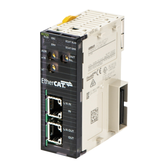
2 Nomenclature and Installation Nomenclature This section provides the nomenclature for the EtherCAT Slave Unit. 2-1-1 Nomenclature and Functions This section provides the names and functions of the items on the front panel of the EtherCAT Slave Unit. Letter Name Function Indicators The indicators show the current operating status of the Unit and... -
Page 47: Indicators
2 Nomenclature and Installation 2-1-2 Indicators An EtherCAT Slave Unit is equipped with the following indicators that provide the operating status of the Unit itself and the overall network. Overview of Indicators Name Meaning L/A IN The L/A IN indicator shows the link activity of the input port. L/A OUT The L/A OUT indicator shows the link activity of the output port. - Page 48 2 Nomenclature and Installation Name Color Status Meaning ECAT ERR • Special Unit Error • ESC Initial Error Blinking • CPU Unit Fatal Error • I/O Bus Error • Output OFF Error • CPU Unit Watchdog Timer Error • CPU Unit Service Monitoring Error •...
- Page 49 2 Nomenclature and Installation Indicator State Timing The flashing patterns for flickering, blinking, single flash, and double flash are given below. 50 ms Flickering Blinking 200 ms 200 ms 1,000 ms Single flash 1,000 ms Double flash 200 ms 200 ms 200 ms 2 - 5 CJ-series EtherCAT Slave Units Operation Manual (W541)
-
Page 50: Switch Settings
2 Nomenclature and Installation 2-1-3 Switch Settings This section describes the functions of the rotary hardware switches on the front panel of the EtherCAT Slave Unit. Unit Number Switch The unit number switch sets the unit number of the EtherCAT Slave Unit as a CPU Bus Unit. The unit number determines which data area words and DM area words are allocated to the Unit that contain data such as unit status, slave status, the I/O Communication Area Setting Table and the I/O Commu- nication Area Reference Table. - Page 51 2 Nomenclature and Installation There are two methods to set the node address: hardware switches and software switches. The switch settings are used to select the method to use. Set the Node Address with Hardware Switches Use the switch settings to set the node address from 1 to 255. If these switches are not set to 00, the node address that is set on the switches will be used.
-
Page 52: Installing The Ethercat Slave Unit
2 Nomenclature and Installation Installing the EtherCAT Slave Unit This section describes how to mount the EtherCAT Slave Unit to a CJ-series PLC system. 2-2-1 System Configuration Precautions Up to 16 EtherCAT Slave Units can be mounted to the CJ-series PLC system when Expansion Racks are present. -
Page 53: Handling Precautions
2 Nomenclature and Installation *1. The maximum number of EtherCAT Slave Units that can be mounted to a CJ-series PLC depends on the model of the CPU Unit. Refer to the operation manual of the specific CPU Unit for more details. Mounting Procedure Carefully align the connectors to mount the EtherCAT Slave Unit. -
Page 54: Ethercat Network Wiring
2 Nomenclature and Installation EtherCAT Network Wiring This section describes how to install the EtherCAT network. 2-3-1 Installation Standards To ensure that the EtherCAT communication network is installed properly, refer to IEC 61784-5-12 standard in conjunction with IEC 61918. 2-3-2 Installation Precautions Basic precautions for the installation of EtherCAT networks are provided below. -
Page 55: Preparations For Installation
Recommended products are given in the following tables. Cables with Connectors Sizes and Conductor Pairs: AWG 22 × 2 Pairs Product name Manufacturer Model Length (m) Cables with Connec- OMRON Corporation XS5W-T421-AMD-K tors on Both Ends XS5W-T421-BMD-K (RJ45/RJ45) XS5W-T421-CMD-K XS5W-T421-DMD-K XS5W-T421-GMD-K... -
Page 56: Pin Arrangements Of Communications Connectors
Nihon Electric Wire & Cable PNET/B Co., Ltd. RJ45 Assembly Connectors Omron Corporation XS6G-T421-1 *1. A combination of the above cables and connectors is recommended for use. Precautions for Correct Use • The maximum length between nodes is 100 m. However, some cables are specified for less than 100 m. -
Page 57: Connecting Communications Cables And Connectors
2 Nomenclature and Installation 2-3-5 Connecting Communications Cables and Connectors Use straight connections for the communications cables and connectors, as shown below. Wire color Wire color Pin No. Pin No. White-Green White-Green Green Green White-Orange White-Orange Blue Blue White-Blue White-Blue Orange Orange White-Brown... - Page 58 2 Nomenclature and Installation EtherCAT master Communications cable Input port Output port EtherCAT slaves EtherCAT Slave Unit Do not connect anything. Last EtherCAT slave Precautions for Correct Use • The cable between any two nodes (L1, L2 ... Ln) must be 100 m or less. •...
-
Page 59: Memory Allocations
Memory Allocations This section describes the words allocated to the EtherCAT Slave Unit. These words both enable controlling the EtherCAT Slave Unit and accessing Unit status. 3-1 Overview of the Memory Allocated to the EtherCAT Slave Unit ..3-2 3-2 CIO Area Allocations . -
Page 60: Overview Of The Memory Allocated To The Ethercat Slave Unit
3 Memory Allocations Overview of the Memory Allocated to the EtherCAT Slave Unit The following CPU Unit words are allocated to the EtherCAT Slave Unit. • CPU Unit’s allocated CIO Area words These words contain the status information. • CPU Unit’s allocated DM Area words These words contain the I/O Communication Area Setting Tables and I/O Communication Area Ref- erence Tables. -
Page 61: Cio Area Allocations
3 Memory Allocations CIO Area Allocations This section describes CIO area allocations for the EtherCAT Slave Unit. 3-2-1 Overview of the Allocated CIO Area Words Various kinds of data are stored in the allocated CIO Area words, which are identified by the offset from the beginning word (n) allocated to each Unit. -
Page 62: Details Of The Allocated Cio Area Words
3 Memory Allocations 3-2-2 Details of the Allocated CIO Area Words This section provides the details of the allocated CIO area words. Unit Status 1 (n+10) 14 13 12 11 10 9 n + 10 Unit Error Slave Function Error Unit Memory Error ESC Error Name... - Page 63 3 Memory Allocations Name Manipulated by Unit operation Unit Memory Error Unit Indicates an error in internal memory where the error log or I/O communication area data is stored. The error occurs when the Unit starts up or when the error log is written. OFF: Indicates that the error did not occur.
- Page 64 3 Memory Allocations Slave Status 1 (n+12) 14 13 12 11 10 9 n + 12 Slave AL Status Error SII Unit Verification Error Verification Error Mailbox Setting Error I/O Communication Error Illegal State Transition Request Received I/O Refresh Error Name Manipulated by Unit operation...
- Page 65 3 Memory Allocations Name Manipulated by Unit operation I/O Communication Unit Error Indicates that RxPDO data from the EtherCAT master is not refreshed during the monitoring time. OFF: Indicates that RxPDO data from the EtherCAT master is refreshed during the monitoring time. Default: OFF Illegal State Transition Unit...
- Page 66 3 Memory Allocations Name Manipulated by Unit operation Input Data Valid Unit Indicates that the Unit is processing transmit by process data communication. Data is valid and usable for con- trol. OFF: Indicates that the Unit is not processing transmit by pro- cess data communication.
-
Page 67: Dm Area Allocations
3 Memory Allocations DM Area Allocations This section describes DM area allocations for the EtherCAT Slave Unit. 3-3-1 Overview of the Allocated DM Area Words The various kinds of data are stored in the offset positions shown in the following diagram, from the beginning word in the area for each Unit. - Page 68 3 Memory Allocations EtherCAT EtherCAT CJ-series master Slave Unit CPU Unit RxPDO OUT data area Output data to EtherCAT Slave Unit TxPDO IN data area Input data to EtherCAT master I/O Communication Area Setting Table Detail Reserved OUT data area type First word in OUT data area m + 1 OUT data area size (byte)
- Page 69 3 Memory Allocations Word Name Manipulated by Default value Function 00 to 07 OUT data area User 00 hex Set the area type code. type • 00 hex: not used • 01 hex: CIO Area (CIO) • 03 hex: Data Memory (DM) •...
- Page 70 3 Memory Allocations Word Name Manipulated by Default value Function m + 4 00 to 15 First word in IN User 0000 hex Set the starting word of the IN data area data area. Setting ranges vary by IN data area type. •...
- Page 71 3 Memory Allocations Precautions for Correct Use • A Unit restart is required after I/O communication allocations are changed or set to enable the new settings. • If the user sets both IN and OUT data area sizes to zero or the I/O allocation settings are invalid, the Unit will be in the Pre-Operational state and cannot perform process data com- munications with the EtherCAT master.
- Page 72 3 Memory Allocations Word Name Manipulated by Default value Function m + 7 00 to 07 OUT data area Unit 00 hex The area type code in use is indi- type cated. • 00 hex: not used • 01 hex: CIO Area (CIO) •...
- Page 73 3 Memory Allocations Word Name Manipulated by Default value Function m + 10 08 to 15 IN data area type Unit 00 hex The area type code in use is indi- cated. • 00 hex: not used • 01 hex: CIO Area (CIO) •...
-
Page 74: I/O Communication Area Settings
3 Memory Allocations I/O Communication Area Settings This section describes the I/O communication area settings, such as IN and OUT data area type, start- ing word and size for the EtherCAT Slave Unit with CX-Programmer. 3-4-1 The Unit Edit Parameters Dialog Box The Edit Parameters Dialog Box of the EtherCAT Slave Unit is used for setting and referencing the I/O communication area table. - Page 75 3 Memory Allocations I/O Communication Area Setting Table Setting Item name Description Data range Default method OUT data area Pull down list PLC memory area type used for • Do not use Do not type RxPDO data from the EtherCAT •...
- Page 76 3 Memory Allocations I/O Communication Area Reference Table Setting Item name Description Data range Default method OUT data area Read Only The reference PLC memory • Do not use Do not type area type used for RxPDO data • CIO Area from the EtherCAT master.
-
Page 77: Setting Procedure With The Cx-Programmer
3 Memory Allocations 3-4-2 Setting Procedure with the CX-Programmer This section provides the setting procedure of the I/O Communication Area Setting Table with CX-Pro- grammer. Double-click IO Table and Unit Setup Icon in the project workspace in the CX-Programmer. The PLC IO Table Window will be displayed. When the EtherCAT Slave Unit is registered in the I/O tables of the CX-Programmer, the Unit will be displayed in the I/O tables. - Page 78 3 Memory Allocations The Edit Parameters Dialog Box will be displayed. Make the necessary settings. I/O Communication Area Setting Table 3 - 20 CJ-series EtherCAT Slave Units Operation Manual (W541)
- Page 79 3 Memory Allocations Place the CX-Programmer online with the PLC and transfer the settings to the EtherCAT Slave Unit. After transferring the settings using the EtherCAT Slave Unit Edit Parameters Dialog Box, a message will ask if you wish to restart the EtherCAT Slave Unit. Click the Yes Button.
- Page 80 3 Memory Allocations Precautions for Safe Use • If the node address is not set correctly, invalid device parameters may be set in the wrong EtherCAT Slave Unit, so check the connected Unit before downloading parameters. • The EtherCAT Slave Unit must restart in order to enable the parameter settings that are transferred to it.
-
Page 81: Ethercat Communications
EtherCAT Communications This section provides an introduction to EtherCAT communications. 4-1 Structure of CAN Application Protocol over EtherCAT (CoE) ..4-2 4-2 EtherCAT Slave Information Files (ESI Files) ..... . . 4-3 4-3 Transitions of Communications States . -
Page 82: Structure Of Can Application Protocol Over Ethercat (Coe)
4 EtherCAT Communications Structure of CAN Application Proto- col over EtherCAT (CoE) EtherCAT allows the use of multiple protocols for communications. However, the EtherCAT Slave Unit uses the CAN application protocol over EtherCAT (CoE) as the device profile for the CAN application protocol. -
Page 83: Ethercat Slave Information Files (Esi Files)
Communications are started according to the communications settings and the network configuration based on the ESI files that are installed. ESI files for the EtherCAT Slave Units can be downloaded from the OMRON website. 4 - 3 CJ-series EtherCAT Slave Units Operation Manual (W541) -
Page 84: Transitions Of Communications States
4 EtherCAT Communications Transitions of Communications States The state transition model for communications control of the EtherCAT Slave Unit is controlled by the EtherCAT master. The following figure shows the communications state transitions from when the power supply is turned Power supply ON Init Pre-Operational... -
Page 85: Process Data Objects (Pdos)
4 EtherCAT Communications Process Data Objects (PDOs) This section describes the process data objects that are used by the EtherCAT Slave Unit. 4-4-1 Introduction Process data objects (PDOs) are used to transfer data during cyclic communications in real time. There are two types of process data objects (PDOs): the RxPDOs, which are used by the EtherCAT Slave Unit to receive data from the EtherCAT master;... - Page 86 4 EtherCAT Communications Object Dictionary Sub- Index Object contents index 01 hex 6TTT hex TT hex 1ZZZ hex 6UUU hex UU hex 02 hex 03 hex 6YYY hex YY hex PDO-Length: 32 bits PDO_1 Object A Object B Object D 6TTT hex TT hex Object A...
-
Page 87: Assigning Pdos
4 EtherCAT Communications TxPDO PDO mapping object I/O Input Data Area object Description Index Sub-index Name Index number Name number number 257th transmit 1B00 hex Input001 6000 hex 01 to 19 hex IN data area size is 50 bytes. PDO Mapping Input025 258th transmit... - Page 88 4 EtherCAT Communications These assignments determine the PDOs to use for communications between the EtherCAT master and slave. Assigning PDOs to EtherCAT Slave Units When assigning PDOs to the EtherCAT Slave Unit, refer to the IN and OUT data area size that have been configured for the EtherCAT Slave Unit.
-
Page 89: Service Data Objects (Sdos)
4 EtherCAT Communications Service Data Objects (SDOs) This section describes the service data objects that are supported by the EtherCAT Slave Unit. 4-5-1 Introduction EtherCAT Slave Units support SDO communications. The EtherCAT master can read and write data from and to entries in the object dictionary with SDO communications to make parameter settings and monitor status. -
Page 90: Communications Performance
4 EtherCAT Communications Communications Performance This section describes the PDO I/O response times and the message response times for the EtherCAT Slave Unit. 4-6-1 I/O Response Time This section describes the method for calculating the maximum I/O response time of the EtherCAT Slave Unit. - Page 91 4 EtherCAT Communications I/O Response Time Formula A formula is provided below to calculate the I/O response time. Maximum I/O Response Time = Tmaster + (4 x Tslave) + (2 x Tcj_plc) + (2 x Ttrans) The elements used in the maximum I/O response time formula are described below. Units of these ele- ments are in ms.
-
Page 92: Sdo Message Response Time
4 EtherCAT Communications 4-6-2 SDO Message Response Time This section describes the method for calculating the minimum SDO message response time of the EtherCAT Slave Unit. The message response time is the time from when the EtherCAT master sends the SDO data with the mailbox until it receives the SDO response from the target EtherCAT Slave Unit. -
Page 93: Troubleshooting
Troubleshooting There are several ways to check errors on an EtherCAT Slave Unit. If an error occurs, refer to this section to troubleshoot the error. 5-1 Error Notification and Checking Methods ......5-2 5-1-1 Error Notification Methods . -
Page 94: Error Notification And Checking Methods
5 Troubleshooting Error Notification and Checking Methods This section describes error notification, checking methods and procedures when an error has occurred in the EtherCAT Slave Unit. 5-1-1 Error Notification Methods The EtherCAT Slave Unit uses the following methods to notify the CJ-series CPU Unit or EtherCAT master that errors have occurred. -
Page 95: How To Check For Errors
5 Troubleshooting Type of error notification Overview Notification method AL status This status reports errors related to Ether- When an error occurs, the error is CAT communications. The ETG-defined written to the AL status register to method is used for the error detection and notify the EtherCAT master. -
Page 96: Procedures To Check Errors
5 Troubleshooting Checking method Information provided Displaying error log for CPU Bus Units The error log is recorded by the error log function of the EtherCAT or Special I/O Units in the I/O table Slave Unit. with CX-Programmer The error log can be read with FINS commands to the Unit. Checking the Unit status and slave These areas indicate the status of the EtherCAT Slave Unit and the level of the error. -
Page 97: Troubleshooting With Indicators
5 Troubleshooting Troubleshooting with Indicators Use the indicators to determine the error status of the EtherCAT Slave Unit. Refer to 2-1-2 Indicators on page 2-3 for information on indicators. 5-2-1 Checking for Errors and Troubleshooting with the Indicators This section provides information for checking errors and troubleshooting with the indicators on the EtherCAT Slave Unit. - Page 98 5 Troubleshooting The flashing patterns for flickering, blinking, single flash, and double flash are given below. 50 ms Flickering Blinking 200 ms 200 ms 1,000 ms Single flash 1,000 ms Double flash 200 ms 200 ms 200 ms 5 - 6 CJ-series EtherCAT Slave Units Operation Manual (W541)
- Page 99 5 Troubleshooting Error Descriptions Errors Related to CPU Unit Data Exchange During Init State or Pre-Opera- tional State Indicator Error Countermea- Error Cause Unit operation ECAT ECAT area sures ERC ERH RUN (hex) Unit Num- The same unit Operation 0006 Set the unit num- bers correctly...
- Page 100 5 Troubleshooting Indicator Error Countermea- Error Cause Unit operation ECAT ECAT area sures ERC ERH RUN (hex) CPU Unit A fatal error An emergency (n+12) Clear the cause Fatal Error occurred in the code is sent if of the error, and bit 01 CPU Unit.
- Page 101 5 Troubleshooting Errors Related to CPU Unit Data Exchange During Operational State or Safe-Operational State Indicator Error Error Cause Unit operation Countermeasures ECAT ECAT area ERC ERH RUN (hex) (n+12) Clear the cause of CPU Unit A fatal error The EtherCAT Fatal occurred in the...
- Page 102 5 Troubleshooting Errors Related to Memory Access Indicator Error Error Cause Unit operation Countermeasures ECAT ECAT area ERC ERH RUN (hex) SII Unit A SII Unit Verifica- The EtherCAT (n+12) Restart the Ether- Verifica- tion Error Slave Unit bit 01 CAT Slave Unit.
- Page 103 5 Troubleshooting EtherCAT Slave Errors Indicator Error Unit opera- Countermea- Error Cause ECAT ECAT tion area sures ERC ERH RUN (hex) I/O Com- The EtherCAT Records the 0345 (n+12) Clear the cause of error in the bit 01 the error and then munica- Slave Unit did not tion Error...
-
Page 104: Corrective Actions When The Cpu Unit's Indicators Are Lit Or Flashing
5 Troubleshooting Others Indicator Error Unit opera- Error Cause Countermeasures ECAT ECAT tion area ERC ERH RUN (hex) IN Port The IN port link is (n+13) Connect the Ether- Link OFF turned off after bit 14 CAT communica- turned on once. tions cable. -
Page 105: Error Log Function
5 Troubleshooting Error Log Function Errors detected by the EtherCAT Slave Unit are stored in the error log along with the date and time of their occurrence. The error log can be accessed by using the CX-Programmer. Refer to the CX-Pro- grammer Operation Manual (Cat. -
Page 106: Error Log Registration
5 Troubleshooting 5-3-2 Error Log Registration This section provides details about the error log registration function of the EtherCAT Slave Unit. Error Log Storage Area When an error occurs, information on the error and the time stamp are stored in the Unit’s internal RAM as an error log record. -
Page 107: Error Log Error Codes
5 Troubleshooting 5-3-4 Error Log Error Codes This section provides details of the error log error codes. Error Detail code Saved in code Error Cause non-volatile First byte Second byte (hex) memory 0001 CPU Unit Watch- An error occurred in the CPU Unit. 00 hex 00 hex dog Timer Error... -
Page 108: Troubleshooting With Emergency Messages
5 Troubleshooting Troubleshooting with Emergency Messages EtherCAT Slave Units are able to report emergency messages to the EtherCAT master by using the SDO communications if they detect errors. 5-4-1 Emergency Message Notification When the power supply is turned ON, the EtherCAT Slave Unit always starts with the Notification set- ting. - Page 109 5 Troubleshooting Error Notification to code Error type Error name Description EtherCAT Corrective action (hex) master FF02 Errors related to CPU Unit A fatal error occurred in the Clear the cause occurred the CPU Unit Fatal Error CPU Unit. error, and restart CPU Unit, and then turn OFF error bit FF03 Output OFF...
-
Page 110: Troubleshooting With Al Status
5 Troubleshooting Troubleshooting with AL Status This status reports errors related to EtherCAT communications. The following table lists the AL status codes that are used with the EtherCAT Slave Units. Notifica- AL status tion to Status name Contents Corrective action code (hex) EtherCAT master... -
Page 111: Maintenance And Replacement
Maintenance and Replacement This section describes the procedures for cleaning, inspecting and replacing EtherCAT Slave Units. 6-1 Cleaning and Inspection ........6-2 6-1-1 Cleaning . -
Page 112: Cleaning And Inspection
6 Maintenance and Replacement Cleaning and Inspection This section describes the routine cleaning and inspection recommended as regular maintenance. 6-1-1 Cleaning Clean the EtherCAT Slave Units regularly as described below in order to keep the network in its optimal operating condition. •... - Page 113 6 Maintenance and Replacement Item Standard Equipment Installation Are the Units installed securely? No looseness Phillips head screwdriver Are the communications connec- No looseness Check visually tors fully inserted and locked? Are the connecting cables undam- No damage aged? 6 - 3 CJ-series EtherCAT Slave Units Operation Manual (W541)
-
Page 114: Replacing Faulty Units
• When a Unit is being returned for repair, attach a sheet of paper detailing the problem and return the Unit to your OMRON dealer. • If there is a faulty contact, try wiping the contact with a clean, lint-free cloth dampened with alcohol. -
Page 115: Appendices
Appendices The appendix provides an example of operations, a programming example to detect valid I/O process data, information on process data exchange in PROGRAM mode, information on CoE objects, supplemental information for creating I/O tables, FINS commands and version information. A-1 Example of Operations for EtherCAT Slave Unit Communications . -
Page 116: Example Of Operations For Ethercat Slave Unit Communications
Appendices A-1 Example of Operations for EtherCAT Slave Unit Communications This section provides an example of operations for EtherCAT Slave Unit communications with an Ether- CAT master. In this example, the NJ-series CPU Unit’s built-in EtherCAT port is used as the EtherCAT master. Refer to the NJ/NX-series CPU Unit Built-in EtherCAT Port User’s Manual (Cat. -
Page 117: A-1-2 Setting Condition
Appendices A-1-2 Setting Condition The following setting conditions are used in this example. I/O Communication Area Setting Table Set the I/O Communication Area Setting Table with the following values. Name Setting value OUT data area type First word in OUT data area 0000 hex OUT data area size 50 byte IN data area type... -
Page 118: Cj1W-Ect21 Setting Procedure
Appendices A-1-4 CJ1W-ECT21 Setting Procedure This section provides the setting procedure for establishing EtherCAT Slave Unit communications. With the power OFF, set the unit number and node address with the corresponding hardware switches. Refer to 2-1-3 Switch Settings on page 2-6. Mount the EtherCAT Slave Unit to the CPU Rack. -
Page 119: A-1-5 Ethercat Master Setting Procedure
Operating Manual (Cat. No. W504) for Sysmac Studio operating procedures. The ESI files for OMRON EtherCAT slaves are already installed in the Sysmac Studio. Update the Sys- mac Studio to get the ESI files for the most recent EtherCAT Slave Unit. - Page 120 Appendices Register the EtherCAT Slave Unit in the network configuration and set the node address of the EtherCAT Slave Unit. The example is shown below. Set the PDO mapping of the EtherCAT Slave Unit. Assign the PDOs of the same size as the set- ting value of the IN and OUT data area size in the I/O Communication Area Setting Table of the EtherCAT Slave Unit.
-
Page 121: A-1-6 Start Ethercat Communication
Appendices Assign the I/O data that is assigned in the PDO mapping settings to device variables. Assign the device variables to I/O ports in the I/O map. Refer to the NJ/NX-series CPU Unit Software User’s Manual (Cat. No. W501) for details on I/O ports and device variables. -
Page 122: Programming Example To Detect Valid I/O Process Data
Appendices A-2 Programming Example To Detect Valid I/O Process Data The following programming example should be used to confirm that I/O process data is valid for an EtherCAT Slave Unit mounted to a CJ-series CPU Unit. This example uses bits in Unit Status 1 and Slave Status 2. Refer to 3-2 CIO Area Allocations on page 3-3 for details of Unit Status 1 and Slave Status 2. -
Page 123: Process Data Exchange In Program Mode
Appendices A-3 Process Data Exchange in PROGRAM Mode When an EtherCAT master or a CJ-series CPU Unit with a mounted EtherCAT Slave Unit enters PRO- GRAM mode, the EtherCAT Slave Unit will continue to exchange process data over the EtherCAT net- work. -
Page 124: A-3-2 Program Example For The Ethercat Master
Appendices A-3-2 Program Example for the EtherCAT Master Use the following program example as a guide to detect that the CJ-series CPU Unit with a mounted EtherCAT Slave Unit enters PROGRAM mode. In the following example, an NJ-series CPU Unit’s built-in EtherCAT port is used as the EtherCAT master. -
Page 125: A-3-3 Program Example For The Ethercat Slave Unit
Appendices A-3-3 Program Example for the EtherCAT Slave Unit Use the following program example as a guide to detect that the EtherCAT master enters PROGRAM mode. A CJ-series CPU Unit with a mounted EtherCAT Slave Unit is used in the example below. The EtherCAT Slave Unit’s unit number is set to 01. - Page 126 Appendices Item Description TTIM(087) instruction Instruction that checks for a stop in bit toggling for a preset time amount that will occur when the EtherCAT master enters PROGRAM mode. Refer to Timing Con- siderations on page A-9. FAL(006) instruction Instruction that creates a user-defined error when the EtherCAT master enters PROGRAM mode.
-
Page 127: A-4 Coe Objects
• PDO mapping objects 2000 to 2FFF hex Manufacturer-specific Area 1 The objects in this area are defined for all OMRON prod- ucts. 3000 to 5FFF hex Manufacturer-specific Area 2 The objects in this area are defined for the EtherCAT Slave Unit. -
Page 128: A-4-4 Communication Objects
Appendices Items with the <> brackets are replaced with data. Each item has the following meaning. Item Description Index This is the index of the object that is expressed as a four-digit hexadecimal number. Subindex This is the subindex of the object that is expressed as a two-digit hexadecimal number. Object name This is the name of the object. - Page 129 Appendices Subin- Index Object Data PDO map- Complete Default Data range Unit Size Access (hex) name attribute ping access (hex) 1009 Manufac- “A“ (padded “A“ (padded Not possible Not possible turer Hard- with 19 with 19 byte ware Version spaces, char- spaces, char- (VS) acter 20 hex)
-
Page 130: A-4-5 Pdo Mapping Objects
Appendices A-4-5 PDO Mapping Objects The PDO mapping objects for the EtherCAT Slave Unit are listed in the following table. Index (hex) Description 1700 to 1703 Receive PDO mappings 1B00 to 1B03 Transmit PDO mappings Subindexes 01 hex and on give the mapped application object information. Bit length Index Subindex... - Page 131 Appendices Subin- Data Index Complete Object name Default Data range Unit attri- Size Access (hex) mapping access (hex) bute 1701 258th receive Possible PDO Mapping Number of 32 hex 32 hex 1 byte Not possi- objects in this (U8) 1st Output Object 70000110 70000110 hex 4 byte...
- Page 132 Appendices Transmit PDO Mapping Objects for the EtherCAT Slave Unit The indexes from 1B00 to 1B03 hex are for transmit PDO mapping objects for the EtherCAT Slave Unit. Subin- Data Index Complete Object name Default Data range Unit attri- Size Access (hex) mapping...
-
Page 133: A-4-6 Sync Manager Communication Objects
Appendices • These objects store the TxPDO entries. Subin- Data Index Complete Object name Default Data range Unit attri- Size Access (hex) mapping access (hex) bute 1B03 260th transmit Possible PDO Mapping Number of C8 hex C8 hex 1 byte Not possi- objects in this (U8) - Page 134 Appendices Subin- Data Index Complete Object name Default Data range Unit attri- Size Access (hex) mapping access (hex) bute 1C10 Sync Manager 0 Possible PDO Assignment Number of 00 hex 00 hex 1 byte Not possi- assigned PDO (U8) • This object provides the number of PDO mappings that are used by Sync Manager 0. •...
- Page 135 Appendices Subin- Data Index Complete Object name Default Data range Unit attri- Size Access (hex) mapping access (hex) bute 1C32 Sync Manager 2 Possible Synchronization Number of Syn- 20 hex 20 hex 1 byte Not possi- chronization (U8) Parameters Synchronization 0000 hex 0000 hex 2 byte...
-
Page 136: A-4-7 Device Profile Area
Appendices A-4-7 Device Profile Area The device profile area for the EtherCAT Slave Unit is listed below. Index (hex) PDO mapping 6000 I/O Input Data Area 7000 I/O Output Data Area I/O Input Data Area This object does not allow complete access. The reading and writing specifications for this object are listed below. - Page 137 Appendices Subin- Data Index Complete Object name Default Data range Unit attri- Size Access (hex) mapping access (hex) bute 7000 I/O Output Data Not possible Area Number of entries C8 hex C8 hex 1 byte Not possi- (U8) Output001 0000 hex 0000 to FFFF 2 byte Possible...
-
Page 138: A-5 Creating I/O Tables
Appendices A-5 Creating I/O Tables This section describes how to create I/O tables for the EtherCAT Slave Unit. A-5-1 I/O Table Overview I/O tables are used to identify Units mounted to the PLC and to allocate I/O to them. With CJ-series PLCs, whenever there is a change to the Unit configuration it is necessary to create I/O tables and reg- ister the mounted Units in the CPU Unit. -
Page 139: A-5-3 Procedure For Creating I/O Tables
Appendices A-5-3 Procedure for Creating I/O Tables This section provides the procedure for creating I/O tables for the EtherCAT Slave Unit using the CX-Programmer. CX-Programmer This section describes how to register an EtherCAT Slave Unit in the I/O tables using the CX-Program- mer (version 9.54 or higher). - Page 140 Appendices The Direct Online Dialog Box will be displayed. Select a serial connection, select the name of the applicable computer serial port, and then press the Connect Button. If the connection process is successful, the system will be connected online. Here, check the operating mode of the PLC.
- Page 141 Appendices Double-click IO Table and Unit Setup Icon in the project workspace in the CX-Programmer. The PLC IO Table Window will be displayed. Select Options - Create from the menus. The EtherCAT Slave Unit will be displayed at the position it is mounted in the PLC. A - 27 CJ-series EtherCAT Slave Units Operation Manual (W541)
- Page 142 Appendices Programming Console This section provides the procedure for creating the I/O tables using a Programming Console. For details on using the Programming Console, refer to the Programming Console’s operation manual. Use the following procedure to create the I/O tables. Additional Information With the CJ Series, it is necessary to create I/O tables only when the user is allocating I/O man- ually.
-
Page 143: A-6 Fins Commands
Appendices A-6 FINS Commands This section explains the FINS commands that are supported by the EtherCAT Slave Unit. A-6-1 Introduction The following FINS command codes can be used to perform various functions with the EtherCAT Slave Unit. Command code Function name CONTROLLER DATA READ ERROR LOG READ ERROR LOG CLEAR... - Page 144 Appendices End Code End code (hex) Description 0000 Normal 1001 Command too large Error Log Read (2102) This command reads the error log. Command Block 21 02 Command Beginning Number code record number records Response Block 21 02 10 bytes 10 bytes Command...
- Page 145 Appendices Parameters Name Description Beginning record num- Specify the first record to be read. The first record number can be specified in the range ber (command) between 0000 and 00F9 hex (0 to 249 decimal). The 0000 hex record is the oldest record.
- Page 146 Appendices Error Log Clear (2103) This command clears the error log for the EtherCAT Slave Unit and resets the number of stored records to 0. Command Block 21 03 Command code Response Block 21 03 Command Response code code ...
-
Page 147: A-7 Version Information
Appendices A-7 Version Information The following table shows the relationship between the Unit version of the EtherCAT Slave Unit, the unit version of the CPU Unit and the version of the CX-Programmer. Refer to version-related information on the CPU Unit for corresponding versions when using CPU Unit versions and CX-Programmer versions that are later or higher than the corresponding versions given in the following table. - Page 148 Appendices A - 34 CJ-series EtherCAT Slave Units Operation Manual (W541)
-
Page 149: Index
Index I - 1 CJ-series EtherCAT Slave Units Operation Manual (W541) - Page 150 Index Index EtherCAT ................ 1-2 EtherCAT master ............1-7 EtherCAT Slave Unit Faulty ..........5-7 AL status ................ 5-3 Ethernet frames .............. 1-2 application objects ............4-5 Available Mailbox Communication ......... 3-7 FINS commands ............A-29 first word in IN data area ..........3-12 cables and connectors ..........
- Page 151 Index node address switches ........... 2-2, 2-6 transmit PDO mappings ..........A-16 twisted-pair cable ............2-11 TxPDO ................3-9 TxPDO Mapping Error ..........5-18 TxPDO Setting Error .............5-18 object name ..............A-13 Online Status ..............3-5 Operational ..............4-4 Other CPU Error ............5-15 OUT data area ..............3-9 Unit Error ................3-4 OUT data area size ............3-11 Unit error ...............5-16...
- Page 152 Index I - 4 CJ-series EtherCAT Slave Units Operation Manual (W541)
- Page 154 The Netherlands Hoffman Estates, IL 60169 U.S.A. Tel: (31)2356-81-300/Fax: (31)2356-81-388 Tel: (1) 847-843-7900/Fax: (1) 847-843-7787 © OMRON Corporation 2015-2019 All Rights Reserved. OMRON (CHINA) CO., LTD. OMRON ASIA PACIFIC PTE. LTD. In the interest of product improvement, Room 2211, Bank of China Tower, No.
Need help?
Do you have a question about the CJ1W- ECT21 and is the answer not in the manual?
Questions and answers