Table of Contents
Advertisement
Quick Links
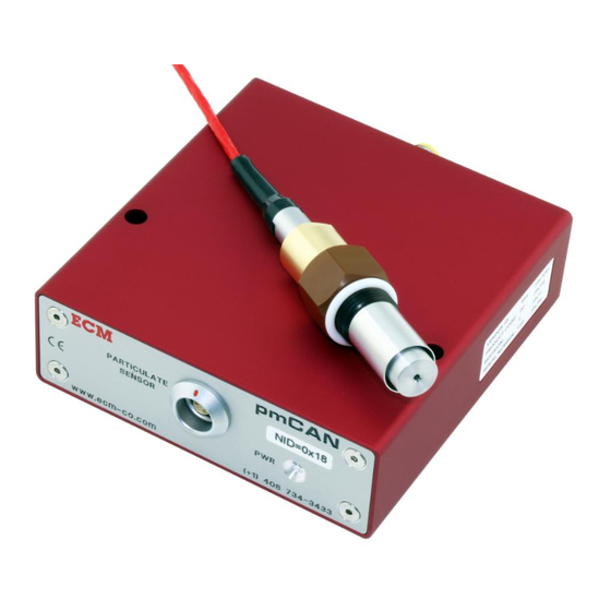
pmCAN Module
Engine Particulate Matter (PM) Measurement
Instruction Manual
Important Note
Due to the nature of CAN instrumentation, you cannot just physically connect a measurement
module to a bus and expect data from that module to be available. The pmCAN measurement
module has to be set up to send the data required and the receiving device (ex. data acquisition
software) has to know what is being sent. The setting up of modules and the production of a .dbc file
used by the receiving device to interpret the data sent is performed using the supplied Configuration
Tool (software) which runs on a PC.
5-24-2021
Advertisement
Table of Contents

Related Manuals for ECM pmCAN Module


Summary of Contents for ECM pmCAN Module
- Page 1 Module Engine Particulate Matter (PM) Measurement Instruction Manual Important Note Due to the nature of CAN instrumentation, you cannot just physically connect a measurement module to a bus and expect data from that module to be available. The pmCAN measurement module has to be set up to send the data required and the receiving device (ex.
- Page 2 COPYRIGHT 2020 by ECM: ENGINE CONTROL AND MONITORING. All Rights Reserved. No part of this manual may be photocopied or reproduced in any form without prior written consent from ECM: ENGINE CONTROL AND MONITORING. Information and specifications subject to change without notice.
- Page 3 Quickstart Manual The PM sensor has three conditions of operation: seeding, normal operation, and fouled. Seeding is necessary before normal operation begins and this will typically take a clean and dry sensor 4 minutes at 1.5 mg/m3. When the PM level is doubled, the seeding time is halved.
-
Page 5: Table Of Contents
CONF (Configure) Setup Option (LEdS, 1V4V, LOCK) Appendices A. pmCAN Kit Contents B. Module Stand-Alone Mode and EIB Mode C. Setting up ETAS INCA for ECM Modules D. Setting up ATI Vision for ECM Modules E. LOCKing and unLOCKing dashCAN* F. Examples of Use... - Page 6 Complex measurement systems can be easily built with pmCAN, LambdaCAN*, NOxCAN*, NH3CAN, and baroCAN modules. Here is a five-channel lambda, O , and NOx pressure-compensated, in-vehicle system.
-
Page 7: Introduction
Introduction The pmCAN module kit is a compact PM (particulate matter) measurement device for use on internal-combustion engines. The PM sensor looks like a spark plug, is screwed into the engine’s exhaust pipe, and operates on a charge-transfer mechanism explained in the section “How the PM Sensor Works”. - Page 8 Click on the “Modules” tab, select the CAN adapter, select the baud rate (all modules shipped from ECM are set at 500kbaud except if they are to be used in a miniPEMS where they are set at 250kbaud), and click on the “START” button.
-
Page 9: How The Pm Sensor Works
How the PM Sensor Works Figure 1 shows the structure of the PM (particulate matter) sensor. There are three concentric metallic bodies: the outer shell, the high voltage (1000V) electrode, and the ground electrode. When mounted perpendicular to the flow in an exhaust pipe, exhaust (with PM) enters the sensor through an annulus in its bottom, passes up between the outer shell and the ground electrode, then through holes and down between the high voltage electrode and the ground electrode, and then out of the sensor through holes in the bottom of the sensor. - Page 10 3. When the engine (and hence exhaust flow) stops, the dendrites on the electrodes will point directly at each other. This will substantially reduce the effective gap between the electrodes and the high voltage across the electrodes will cause a slow “tree-trimming” effect.
- Page 11 Figure 2 contains a more descriptive diagram of the sensor and the external measurement electronics. Note from the figure the following: 1. The dendrites that look like black fur in the sensor. Broken off pieces of dendrites will carry charge across the electrodes (resulting in “IST” current). These pieces may remain on the other electrode, or trigger another dendrite break and charge transfer, or may exit the sensor.
- Page 12 Figure 2: PM Sensor and Electronics...
-
Page 13: Application Notes
Application Notes Safety Note: To avoid getting shocked by the 1000V applied to the sensor or possibly damaging the pmCAN’s electronics, always turn the 1000V off before removing or attaching the sensor from the cable (or the cable from the module). This is done using the Task: “Toggle High Voltage”. - Page 14 Sometimes, the fouling will clean itself. It doesn’t clear in 15 minutes, the sensor will have to be taken out of the exhaust and blown out with compressed air for about 10 seconds. In extreme cases, the sensor will need to be disassembled and cleaned. Appendix G describes how to clean the sensor which should take less than 5 minutes.
- Page 15 Interpolation is performed between the points in the tables. Unlike the ZEROs and SPANs, the Delta Tables are stored in the pmCAN module and are applied to any sensor attached to that module. The Delta Tables are entered and programmed into the pmCAN module...
- Page 16 Delta Tables are in the modules. The reason for this is that once a user determines the Delta Table for one sensor, it is likely that all ECM sensors with a factory calibration will give similar results when connected to the same module. In addition, these Delta Tables can be downloaded into other pmCAN modules.
- Page 17 Appendix F: Appendix F is located in the back of this manual and contains examples of pmCAN in use.
-
Page 18: Configuring A Module
Configuring a Module Normally, you will be configuring a module to be used in stand-alone mode. Stand-alone mode is used when the modules are connected to a CAN bus that goes directly to a data acquisition or control system. In stand-alone mode, a module’s configuration is performed by selecting one of the tasks in the “Task”... - Page 19 Change Node ID: Allowable range 0x01 to 0x7F (hex). When you assign a Node ID (NID), the following CAN IDs cannot be used by any other devices on the bus: 0x00, 0x80 + NID, 0x180 + NID, 0x280 + NID, 0x380 + NID, 0x480 + NID, 0x580 + NID, 0x600 + NID, 0x700 + NID, 0x7E4, 0x7E5.
- Page 20 Toggle High Voltage: Turns the 1000V electrode on and off. To avoid getting shocked by the 1000V applied to the sensor or possibly damaging the pmCAN’s electronics, always turn the 1000V off before removing or attaching the sensor from the cable (or the cable from the module).
-
Page 21: Selecting What Data Is To Be Sent (Tpdos) And Error Codes
TPDOs to be used by clicking in its box to put in a check mark. Select the data contained in each TPDO using the pull-down windows. The list of available parameters for the pmCAN module is given in Table 2. Parameters PM and PN should be used for PM mass and number densities (not PMR and PNR). - Page 22 Actual High Voltage Electrode Voltage (0-2000 V) VHVC High Voltage Electrode Voltage Command (0-2000 V) VILK Voltage output of Sensor Leakage Current Circuit (0-5000 mV) VIST Current Measurement Voltage (0-5000 mV) Supply Voltage at pmCAN Module (0-40 V) Table 2: pmCAN Parameter List...
- Page 23 ECM Error Code LED Action Description of Error (hex) (R=red, G=green) 0x00 G On All OK 0x01 Flash G @ 10hz Start-Up 0x02 G,G&R,R @ 2s Power ON Reset/Init Hardware 0x13 R On High Voltage Off 0x14 Flash R 1x @ 2s...
-
Page 24: Producing A .Dbc File
Producing a .dbc File A .dbc file describes to the device receiving data from one or more CAN modules what is in the data packages. For each module, the packages will contain data for the parameters selected in the activated TPDOs and an error code. The Configuration Tool has a tool called “Generate .dbc…”... -
Page 25: Using The Dashcan* Display
“T” (P/N 09-05). Simply attach dashCAN* to the CAN bus and parameters from one or two ECM CAN modules can be displayed and converted to analog outputs (dashCAN2 or dashCAN+ only). The top display and half the analog outputs can be assigned to one module and the bottom display and the other half of the analog outputs can be assigned to the same or another module. - Page 26 When first entering SYS mode, either “MOd” will be on the top display or “LOCK” will be on the bottom display. If “MOd” is displayed, the and keys will roll through the setup options (see Table 4). First the options for the module assigned to the top display are shown on the top display, followed by identical options for the module assigned to the bottom display, ending with the global CONF (Configuration) setup.
-
Page 27: Mod (Module) Setup Option
MOd (Module) Setup Option In MOd setup, the serial number of the module assigned to the top or bottom display is entered. The serial number is written on a label on the module. The module assigned to the top display will be assigned the first half of the analog outputs. The module assigned to the bottom display will be assigned to the second half of the analog outputs. -
Page 28: Disp (Display) Setup Option
Here is an example of setting analog output 2 for a dashCAN+ (i.e. A2): 1. Press the SYS key so that “MOd” appears on the top display. 2. Press the key until “AOUT” is on the top display. Then press the ENT key. 3. - Page 29 1V4V (dashCAN2 and dashCAN+ only) “1V4V” commands the analog outputs to go to 1V then 4V. This is used to verify that the data acquisition system reading the analog outputs is correctly reading them. LOCK “LOCK” locks the MOd, RATE, AOUT, dISP, and LEdS setup. This stops unauthorized modification of the display.
-
Page 30: Appendices
Appendix A: pmCAN Kit Contents... - Page 31 The pmCAN Kit consists of: Description Quantity 1. pmCAN Control Module 02-15 2. PM Sensor (tailpipe application) or 06-10T PM Sensor (diesel engine-out application) 06-10E 3. PM Sensor Cable, (2m) 10-48 4. Flexi-Eurofast Cable, (0.3m) 09-04 5. Eurofast “T” 09-05 6.
-
Page 32: Module Stand-Alone Mode And Eib Mode
Appendix B: Module Stand-Alone Mode and EIB Mode CAN data from CAN modules (ex. pmCAN, NH CAN, NOxCAN, LambdaCAN) can either be taken directly from the modules themselves or from the CAN port of display heads connected to the modules. When data is taken directly from one or more modules, each module must in Stand-Alone mode. - Page 33 2. Using 5/64” (or 2mm) hex wrench, remove the 4 screws on the front of the module. 3. Slide the PCB out. Put the jumper on both pins for Stand-Alone Mode. Jumper...
- Page 34 4. Make sure the O-ring is on the eurofast connector. 5. Slide the PCB back into the enclosure and reattach the four screws on the front of the module. 6. Put the washer and nut on the eurofast connector and tighten. 7.
- Page 35 8. Start the Configuration Tool (software). Click on the “Module” tab. Select the CAN adapter being used. Then start the communication. 9. Click on the “Stand-Alone” button. Wait for the “Done” Message. Stop communication and exit program. The module is in Stand-Alone Mode. To convert a module from Stand-Alone Mode to EIB Mode ...
-
Page 36: Setting Up Etas Inca For Ecm Modules
2. Connect the Ethernet port directly to the Ethernet port on your PC. This port does not use an internet/intranet connection like a router. 3. Connect either the CAN1 or CAN2 port to a CAN network (i.e. ECM modules or display heads). - Page 37 5. Configure the hardware. Click on the icon for the workspace you created in step 3. Open the Hardware Configuration icon under the section text “6. Hardware”. A hardware configuration window will open.
- Page 38 6. Select the hardware. In the hardware configuration window, right click the “HWK Workspace” listed under the section text “1. Hardware Devices”, and select Insert. Select the ETAS device you wish to use. In this example, we are using an ETAS ES591.1.
- Page 39 8. Initialize hardware. The hardware is currently stopped, as indicated by the red stop sign icon next to the selected hardware. You must initialize it before you can use it to collect data. Click on the Initialize Hardware button on the upper tool bar and wait for the hardware to complete its initialization.
- Page 40 10. Select and Configure Variables. Select the variables that you wish to monitor in the Experiment Environment. These variables names are based on the data found in the dbc file. Click Configure. 11. Another window will pop up to configure each selected variable. You can configure, for each variable, whether to record or simply display the data, how the data will be displayed (graphs, charts, gauges, numeric, etc.).
- Page 41 13. Start CAN monitoring. Right now there is no data displayed. That is because the CAN monitoring is stopped. To begin CAN monitoring, click on the Start Visualization icon (blue triangle) on the left hand tool bar. To stop CAN monitoring, click the Stop Measuring icon (black square) on the left hand tool bar.
-
Page 42: Setting Up Ati Vision For Ecm Modules
Appendix D: Setting Up ATI Vision for ECM Modules NOTE: While shown here for a single LambdaCAN module, the same procedure applies for any of ECM’s CAN-based devices as well as for multiple modules simultaneously connected on the same bus. Introduction Connecting ECM LambdaCAN hardware to ATI VISION software is simple and does not require any third-party software interface. - Page 43 Creating a .dbc File The ECM Configuration Tool is used to create a .dbc database file for describing the CAN messages broadcast from the LambdaCAN. All ECM products with a CAN interface use the CANopen protocol at 500kHz by default. To generate a .dbc file using ECM Configuration Tool: 1.
- Page 44 ATI VISION CANMonitor provides a method of reading general purpose information from any available CAN channel. The .dbc file generated by the ECM Configuration Tool is used to describe the format of the information available to VISION. To setup a CANMonitor in ATI VISION: 1.
- Page 45 3. Add a physical hardware device by clicking Device Add Device, and select Kvaser CAN Channel. 4. Select a CANMonitor device by again clicking Device Add Device, and select CANMonitor.
- Page 46 5. Add the .dbc file generated from the ECM Configuration Tool to CANMonitor by clicking Device Add CAN Database and browsing to the previously created .dbc file. 6. Enable the hardware by clicking Project Online. The status of all of the devices should now show a Status of Online, and a value should appear in the Data Rate column of the Project window.
- Page 47 7. To view data, create a new Screen File and add a Control. Click File New Screen File 8. Select Object Add Control Gauge...
- Page 48 9. In the Select Data Items window open the CANMonitor file tree to view all of the available signals. Here the O2% from Node 0x10 has been selected. Click OK to add the Data Item to the Control. 10. Data should be visible on the gauge.
-
Page 49: Locking And Unlocking Dashcan
1. Press SYS until “LOCK” is displayed. Then press ENT. 2. “50” will be displayed. Press until “60” is displayed. Then press ENT. dashCAN* is now unLOCKed. If an unauthorized person learns that 60 is the key number, contact ECM. -
Page 50: Examples Of Use
Appendix F: Examples of Use This example shows a light duty diesel truck with a DPF and 70,000 km getting on and driving on the highway. PM sensor mounted tailpipe-out. - Page 51 This example shows a light duty diesel truck with a damaged DPF getting on and driving on the highway. PM sensor mounted tailpipe-out.
-
Page 52: Cleaning The Pm Sensor
Appendix G: Cleaning the PM Sensor Cleaning the PM sensor should take less than 5 minutes and will not affect the calibration. This is the PM Sensor Cleaning Kit, P/N 14-15. The thin wrenches are key. You will need some extra things to clean a sensor: a roll of paper towels, a can of brake cleaner (or acetone), a pair of scissors, and compressed air. - Page 53 First step is to remove the outer shell. Sometimes it’s a little sticky. Go easy. Then remove the ground electrode:...
- Page 54 If it is not so, you will have to send the sensor back to ECM. Note the soot pattern. Spray some brake cleaner on a piece of paper towel and wipe off the side and end of the high...
- Page 55 Then blow dry air on the electrode and the annulus between the electrode and the body of the sensor. You need to remove all the towel’s particles, PM particles, and evaporate the solvent. Normally, you do not have to clean in the annulus. If you do, you can use a q-tip soaked in brake cleaner.
- Page 56 Now spray some brake cleaner inside the ground electrode and clean the inside of the electrode with a small piece of paper towel soaked in brake cleaner. Sometimes you’ll also want to use the brush but most of the time, the soaked paper towel will be sufficient.
- Page 57 Clean the outside and bottom of the ground electrode with a clean part of the towel, and blow it out with compressed air. It should be clean inside, outside, and all those little holes should be clean too.
- Page 58 During your cleaning and blowing, keep away from the teflon tape. Rarely will it need to be replaced. This is when it is flaking off. Cut off any little loose pieces that are waving around in the wind because they will cause jumpy PM readings. If you have to replace the teflon tape, carefully clean the old tape completely from the treads, cut the tape to the width of the threads and wrap the tape tightly and clockwise around the threads once and overlapping by a few mm.
- Page 59 Now clean the outer shell. Again, sometimes you’ll want to use the brush but most of the time, a brake cleaner-soaked piece of paper towel is sufficient. Blow it out with air after cleaning.
- Page 60 Time to reassemble the sensor. First screw in the ground electrode by hand and snug it down a bit with the wrench. Do not overtighten. Actually, the main purpose of the wrenches is to take the sensor apart so don’t overtighten and strip the threads when reassembling. Then screw on the outer shell.
- Page 61 Holes look clean? You didn’t drop the sensor, did you? The annulus should be even around the ground electrode (i.e. everything should be symmetric and centered). Blow it out one more time. Yes, there is a lot of blowing out. You need to clean out flakes of soot, pieces of paper towel, and to evaporate any solvent.
- Page 62 Santa Clara, CA 95054 AND MONITORING Phone: (408) 734-3433 FAX: (408) 734-3432 Email: sales@ecm-co.com Web: www.ecm-co.com EC DECLARATION OF CONFORMITY We declare under our sole responsibility that the products: AFM1540 Lambda Module AFM1600L, AFM1600D Modules DIS1000 Display head EGR 4830 Analyzer...
- Page 64 • • • • Los Altos, CA 94023-0040 (408) 734-3433 Fax: (408) 734-3432 www.ecm-co.com...
Need help?
Do you have a question about the pmCAN Module and is the answer not in the manual?
Questions and answers