Table of Contents
Advertisement
Quick Links
Advertisement
Table of Contents

Related Manuals for ECM XCM114


Summary of Contents for ECM XCM114
- Page 1 XCM114 , Lambda, AFR Module Instruction Manual 07/15/2014. P/N XCM114-4...
- Page 2 No part of this manual may be photocopied or reproduced in any form without prior written consent from ECM: ENGINE CONTROL AND MONITORING. Information and specifications subject to change without notice. XCM114 is a trademark of Engine Control and Monitoring. Printed in the United States of America.
-
Page 3: Safety Warnings
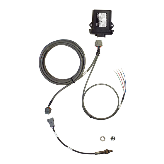
Safety Warnings In the installation and use of this product, comply with the National Electrical Code and any other applicable Federal, State, or local safety codes. Always wear eye protection when working near engines, vehicles, or machinery. During installation, turn off the power and the engine and take all other necessary precautions to prevent injury, property loss, and equipment damage. - Page 4 XCM114 Kit Contents Not pictured: This instruction manual, P/N XCM114-4.
-
Page 5: How To Use
Do not run a single wire from where the BLK and WHT wires join to the power supply ground. Contact ECM for harness modification questions. In the case of a detected failure, the output of the XCM114 will be encoded with a “pulsed” trouble code that will describe the failure. See “Troubleshooting” section. -
Page 6: Output Signal
Values for %O , Lambda, and AFR (gasoline) can be determined using two methods. “Method #1” assumes an “as delivered” sensor from ECM. “Method #2” is for a sensor of unknown condition and requires a pre-calibration in air. Method #1 (for new sensors): 1. - Page 7 Vout & Iout vs %O Vout (V) Iout (mA) Type -6.967 0 6.967 13.93 20.9 -6.967 0 6.967 13.93 20.9 -6.967 0 6.967 13.93 20.9 -5.219 -2.61 2.61 5.219 7.829 10.44 13.05 15.66 18.27 20.88 -7.829 -5.219 -2.61 2.61 5.219 7.829 10.44 13.05 15.66 18.27 20.88 -7.829 -5.219 -2.61 2.61 5.219 7.829 10.44 13.05 15.66 18.27 20.88...
- Page 8 Pressure Compensation Equation for AFR = (AFR + B x P) / (1 + C x P) [Equation 3a] corrected measured where: AFR = the AFR corrected for exhaust pressure. corrected = the AFR output by the AFM. measured = 0.009140 for AFR < 14.57 (rich). = 0.012100 for AFR ≥...
- Page 9 Modes of Operation (Voltage Output or Current Output Voltage output mode (Vout- and GND are connected internally): Current output mode, using internal (Int) power (i.e. Current Transmitter Type 3): Current output mode, using external (Ext) power (i.e. Current Transmitter Type 4): in 4-20mA systems is typically 50Ω, 100Ω, 250Ω, or 500Ω.
- Page 10 Changing Modes, Current Output Power Sources, and Types The modes and current power sources are set by two toggle switches inside the module. The type is set by an 8-position dip switch inside the module. To modify: 1. Disconnect the module from its harness. 2.
- Page 11 4. The switch for type settings is located on the upper left of the board labeled S2. Set the positions of the switches according to the table below. Note that only the switches listed for each type should be set to on, all others are off. The on position is with the switches flipped to the left.
-
Page 12: Troubleshooting
Troubleshooting Trouble codes are output as LED flashes and as signal output pulses. The pulses are active low, so the signal will be pulled low for each pulse. In voltage output mode, 0V indicates a low state. In current output mode, 4mA indicates a low state. This allows for both visual indication as well as indication for the integrated diagnostic system. -
Page 13: Warranty And Disclaimers
Warranty and Disclaimers WARRANTY The products described in this manual, with the exception of the O sensor, are warranted to be free from defects in material and workmanship for a period of one year from the date of shipment to the buyer. Within the one year warranty period, we shall at our option replace such items or reimburse the customer the original price of such items which are returned to us with shipping charges prepaid and which are determined by us to be defective. -
Page 14: Appendix A: Calculating The %O
Appendix A: Calculating the %O in Air The oxygen concentration in dry air (zero humidity) is 20.945 and decreases with increasing humidity. The %O in air can be calculated from the barometric pressure (P , in mmHg), the relative humidity (Rh), and the saturated water vapor pressure (P , in mmHg) by using the following formula: = 20.945% x (P... - Page 16 Los Altos, CA 94023-0040 USA (408) 734-3433 Fax: (408) 734-3432 www.ecm-co.com...
Need help?
Do you have a question about the XCM114 and is the answer not in the manual?
Questions and answers