
Related Manuals for ECM LambdaCANp


Summary of Contents for ECM LambdaCANp
- Page 1 ENGINE CONTROL AND MONITORING LambdaCANp Lambda CAN Module Instruction Manual REV 1.31 9/11/14...
- Page 2 DESCIPTION SECTION 1.00 7/1/2011 Original Release 1.20 2/2/2012 "ERFL" and "ERCD" changed to "UERF" and"UERC". Added new ECM OS Commands. 1.30 2/16/2012 Added CAN baudrate setting, Delta tables, 8.12 - 8.17 and Pressure sensor calibration. Modified appendix G 1.31 9/11/2014...
- Page 3 Fax: 408-734-3432 Sunnyvale, CA 94089 USA www.ecm-co.com COPYRIGHT 2014 by ECM: ENGINE CONTROL AND MONITORING. All Rights Reserved. No part of this manual may be photocopied or reproduced in any form without prior written consent from ECM: ENGINE CONTROL AND MONITORING.
-
Page 4: Table Of Contents
Connecting the LambdaCANp module Application Notes Overall Dimensions Getting Information from the LambdaCANp Module CANopen Message Types Writing to the LambdaCANp Module (SDO Write) Reading from the LambdaCANp Module (SDO Read) Identifying the LambdaCANp Module Commands to the LambdaCANp Module SPANing O... -
Page 6: Introduction And General Notes
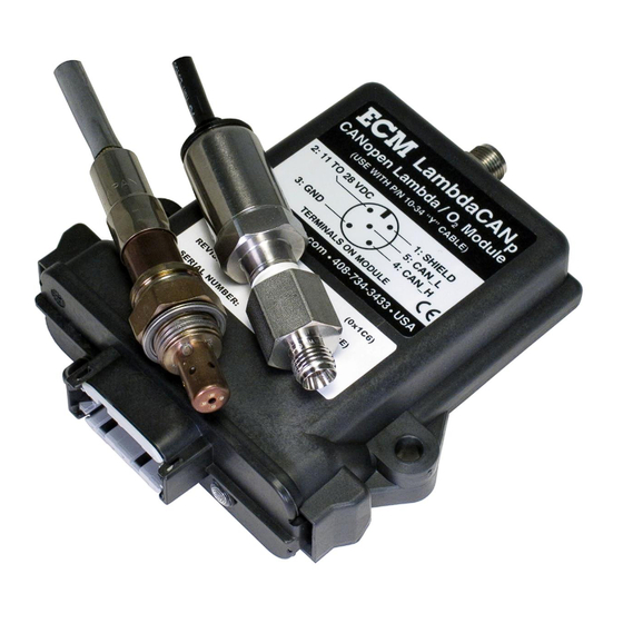
Introduction and General Notes Introduction The LambdaCANp kit is a ceramic sensor-based Lambda, AFR, O , and pressure (optional) measurement system that communicates and is configured via the CANopen protocol. Its primary application is for the analysis of combustion systems and their after-treatment. -
Page 7: Parts
Parts The LambdaCANp Kit consists of: PART 1. LambdaCANp Control Module 02-08 2. LambdaCANp Sensor (Kit P/N: LCAN-N) 05-01 (NTK 6mA) or (Kit P/N: LCAN-B2) 05-02 (BOSCH LSU4.2) or (Kit P/N: LCAN-B9) 05-03 (BOSCH LSU4.9) or (Kit P/N: LCAN-N4) 05-04 (NTK 4mA) or... -
Page 9: Connecting The Lambdacanp Module
CAN bus operating at a 500kBit/s baud rate is 100m. Each end of the CAN bus must have a terminating resistor of 121 Ohms. Application Notes 1. Configuration software (ECM Configuration Tool) for the module is located on the CD. This software allows the setup, configuration, monitoring, and recording of data using supported CAN adapters. -
Page 10: Overall Dimensions
Overall Dimensions... -
Page 11: Getting Information From The Lambdacanp Module
P byte 0x00 L byte = Lambda sensor ECM Error Code (0x01 = Sensor Warm-up, 0x00 = Data valid etc, see Appendix A) count = Sensor Warm-up countdown in seconds (active during ECM Error Code 0x01) P byte = Pressure sensor ECM Error Code (0x00 = Data valid etc, see Appendix A) - Page 12 iii) TRANSMIT PROCESS DATA OBJECT [TPDO] (Broadcast rate = 0.005sec, DLC=8) TPDO1 CAN id byte 0 byte 1 byte 2 byte 3 byte 4 byte 5 byte 6 byte 7 0x180+NID Lambda (AFR/AFRstoic) TPDO2 CAN id byte 0 byte 1 byte 2 byte 3 byte 4...
-
Page 13: Writing To The Lambdacanp Module (Sdo Write)
Configuration of the LambdaCANp module is performed by writing to the Object Dictionary (OD) and by issuing ECM CANopen OS Commands (OS Command). Both of these actions are implemented using a Service Data Object Expedited Write (SDO Write). The format is as... -
Page 14: Reading From The Lambdacanp Module (Sdo Read)
Reading from the LambdaCANp Module (SDO Read) During configuration it may be necessary to read certain locations in the Object Dictionary (OD). The format for a Service Data Object Read (SDO Read) is as follows: SDO Read Tx byte 0... -
Page 15: Identifying The Lambdacanp Module
Identifying the LambdaCANp Module Each LambdaCANp module can be uniquely identified by reading the following four parameters in the OD: Vendor ID (0x000001C6) located at OD address 0x1018, subindex 0x01 (4 byte integer/unsigned 32) Product Code (LambdaCANp = 0x0000000E) located at OD address 0x1018... -
Page 16: Commands To The Lambdacanp Module
Commands to the LambdaCANp Module There are several commands that can be used with the LambdaCANp module. The commands are executed by performing an SDO Write to OD address 0x1023, subindex 0x01. A list of the commands can be found in Appendix B. -
Page 17: Canceling (Erasing) The Span
0x01 0x0E If the ECM Error Code is from 0x10 to 0x3F inclusive, there is a problem with the module and/or the sensor memory. Therefore the SPAN will be ignored. A successful SPAN can be determined by reading locations 0x5000 and 0x5001 in the OD by performing an SDO Read. If the SPAN was successful those locations will read as 99999.0. -
Page 18: Returning The Pre-Broadcast Averaging To Factory Default
Changing the NID The Node ID (NID) can be programmed from 0x01 to 0x7F (1 to 127). To change the NID, several messages must be sent to the LambdaCANp module. This must be followed by a reset of the module. - Page 19 on the top of the plastic enclosure). Note that the data is sent LSB first. For example, if the serial number is 0x12345678, then byte1 = 0x78, byte2 = 0x56, byte3 = 0x34, byte 4 = 0x12. MULTIPLE MODULES ON BUS SINGLE MODULE ON BUS CAN id byte 0...
-
Page 20: Changing The Tpdo Broadcast Rate
(see section 8.7). It is an unsigned 16bit integer (2 bytes) written least significant byte (LSB) first (Intel format) to OD address 0x1800, subindex 0x05. The format of the SDO Write to the LambdaCANp module is as follows: CANid... -
Page 21: Enable Transmit Process Data Object (Tpdo)
CAN bus and how many TPDOs have been enabled for each module. If the broadcast rate is too fast the ECM Configuration Tool will not be able to identify or configure any of the modules. The formula for calculating the minimum broadcast rate is as follows: Minimum Broadcast Rate (ms) >... -
Page 22: Disable Transmit Process Data Object (Tpdo)
Example: Enable TPDO4 for the module with NID = 0x20, (EnableOD Address = 0x1803, Transmit CANid = 0x480 + 0x20 = 0x4A0). CANid byte 0 byte 1 byte 2 byte 3 byte 4 byte 5 byte 6 byte 7 0x620 0x23 0x03 0x18... - Page 23 Also, the following information is required to successfully map a TPDO. TPDO ConfigOD EnableOD Transmit Address Address CANid TPDO1 0x1A00 0x1800 0x180 + NID TPDO2 0x1A01 0x1801 0x280 + NID TPDO3 0x1A02 0x1802 0x380 + NID TPDO4 0x1A03 0x1803 0x480 + NID Write a 0 to the TPDO Configuration OD Address, subindex 0x00 by performing a SDO Write as follows: CANid...
-
Page 24: Entering Fuel Constants
The module and sensor are compatible with hydrogen fuels. To configure the module for hydrogen fuel requires sending the ECM CANopen OS Command 0x19 (EnableH2Calc) via an SDO Write. The H:C, O:C, N:C constants are ignored until the hydrogen fuel mode is disabled. -
Page 25: Setting The Can Baudrate
8.12 Setting the CAN baudrate To change the CAN baudrate, several messages must be sent to the LambdaCANp module. This must be followed by a reset of the module. The procedure described below will change the CAN baudrate on ALL modules. If there are multiple modules on the CAN bus during this procedure, all the modules must be communicating at the same baudrate. - Page 26 CAN id byte 0 byte 1 byte 2 0x7E5 0x13 0x00 Index Where “Index” corresponds to the following baud rates: 0 = 1000kBbit/s 1 = 800kBbit/s (Not supported. Do not use.) 2 = 500kBbit/s (Max bus length 100m) 3 = 250kBbit/s (Max bus length 250m) 4 = 125kBbit/s (Max bus length 500m) 5 = Reserved 6 = 50kBbit/s...
-
Page 27: Modifying The Delta Lambda Table
31 entries are used, the table must be appended with an end of table character (0x7FFF). The LAMR index table is located at ECM OD location 0x5015 and is formatted as signed 16bit integers and scaled by 1000 as shown below:... -
Page 28: Modifying The Delta O2 Table
31 entries are used, the table must be appended with an end of table character (0x7FFF). The O2R index table is located at ECM OD location 0x5013 and is formatted as signed 16bit integers and scaled by 100 as shown below:... - Page 29 0x1F signed 16 RD/WR * 100 ∆ The corresponding value table is located at ECM OD location 0x5014 and is formatted as signed 16bit integers and scaled by 1000 as shown below. ADDRESS SUBINDEX SIZE READ/WRITE SCALING ∆ * 1000...
-
Page 30: Clearing The Delta Lambda / Delta O2 Table
4. Update the user CAL YEAR by writing to OD location 0x5059 subindex 0x70 and the user CAL DATE by writing to OD location 0x5059 subindex 0x71. 5. Write the data to the pressure sensor memory by issuing ECM OS Command 0x5B and read the OS Status and OS Reply (ProgUserPcal, see Appendix B). - Page 31 The OD location 0x5059 is formatted as shown below. Note the scaling and the units of each entry. Also note that subinex 0x5F is reserved. Do not write to this location. ADDRESS SUBINDEX SIZE READ/WRITE SCALING 0x5059 0x50 unsigned 16 RD/WR PVLT 1 (Volts * 10000) 0x51 unsigned 16 RD/WR...
-
Page 32: Restoring The Pressure Sensor Calibration To Factory Default
8.17 Restoring the Pressure Sensor Calibration to Factory Default To revert back to the factory pressure sensor calibration issue ECM OS Command 0x59. Connect the pressure sensor to the module using cable p/n 10-34. Apply power to the module and issue the ECM OS Command as shown below. -
Page 33: Appendix A: Error Codes And Error Register
Appendix A: Error Codes and Error Register CAN id byte 0 byte 1 byte 2 byte 3 byte 4 byte 5 byte 6 byte 7 0x80+NID Error Error Error Lambda Lambda Pressure\ Pressure\ Code lo Code hi Register Error lo Error hi Error lo Error hi... - Page 34 Serial overrun 0x00B7 Can overrun Lss 0x00B8 Can overrun Sdo 0x00B9 Can overrun Rx 0x00BA Can overrun ECT5 0x00FF Both ON Module powering down within 500ms ECM AUX Lambda sensor warm-up count down in seconds (active during ECM Error Code 0x0001)
-
Page 35: Appendix B: Ecm Canopen Os Commands
Appendix B: ECM CANopen OS Commands A user-specific CANopen OS Command to the LambdaCANp module is sent using an SDO expedited write message in the following form. These commands apply only to the LambdaCANp module and are listed on the following page:... - Page 36 COMMAND VALUE DESCRIPTION REPLY SensorOn 0x07 Turn on sensor power None SensorOff 0x08 Turn off sensor power None OWDisable 0x0A Ignore 1wire memory (OWDisabled) and use None EE memory values, unit subsequently performs defForceOW/EERead OWEnable 0x0B Use 1wire memory values (OWEnabled), None unit subsequently performs defForceOW/EERead...
- Page 37 0x1D Set all delta %O2 values to 0 None ResetDeltaLambdaTable 0x1E Set all delta Lambda values to 0 None ResetTPDOs 0x1F Set all TPDOs as delivered from ECM None FastSensorStart 0x20 Use sensor start parameters in 1wire None memory SlowSensorStart 0x21 Sensor start draws <1A max...
-
Page 38: Appendix C: Heartbeat
Appendix C: Heartbeat A Heartbeat message is transmitted every 0.5 seconds by the LambaCAN module. During normal operation the module is in operational mode (NMT state = 0x05). CAN id byte 0 byte 1 byte 2 byte 3 byte 4 byte 5 byte 6 byte 7... -
Page 39: Appendix D: Process Data Objects
0x200E single float UERF PDO Data Lambda Error bit flags 0x200F single float UERC PDO Data ECM CANOpen Lambda Error Code 0x2010 single float PR10 PDO Data 10bit Praw (bits) 0x2011 single float PDO Data PCF (Pressure Correction Factor) * 10000... -
Page 40: Appendix E: Sensor Constants
The module can be configured to use generic sensor constants which can be modified by the user by issuing the proper ECM CANopen OS Command (see Appendix B). The memory locations are organized as shown below:... - Page 41 The procedure for using the generic sensor constants is as follows: 1. Disable the 1WIRE memory in the sensor connector by issuing ECM CANopen OS Command 0x0A. 2. Load the appropriate sensor constants from ROM into EEPROM by writing the sensor type to OD location 0x5017.
- Page 42 = 0x0205 (517) BOSCH LSU4.9 UEGO = 0x0206 (518) DELPHI OSL UEGO Example: Disable 1WIRE sensor memory (ECM CANopen Command 0x0A), load sensor constants for a BOSCH LSU 4.9 UEGO (SDO Write 0x0205 to OD address 0x5017), and modify the RVS TARGET to 150 ohms (SDO Write to 150*10 = 0x05DC to OD...
-
Page 43: Appendix F: Calculating The %O In Air
Appendix F: Calculating the %O in Air The oxygen concentration in dry air (zero humidity) is 20.945 and decreases with increasing humidity. The %O2 in air can be calculated from the barometric pressure (Pb), the relative humidity (Rh), and the saturated water vapor pressure (Pws) by using the following formula: %O2 = 20.945% x (Pb - Pws x (Rh/100)) / Pb The saturated water vapor pressure (Pws) is a function of the ambient temperature (Ta) and is given in the table below. -
Page 44: Appendix G: Module Eib Mode And Stand-Alone Mode
Module EIB mode and Stand-alone Mode The LambdaCANp module can be used in conjunction with a display head (EIB mode) or on its own (Stand-alone mode). When delivered to be used with a display head, the module is setup in EIB mode. - Page 45 2. Install and start the Configuration Tool (software). Click on the “Module” tab. Select the CAN adapter being used. Then start the communication. 3. Click on the “Set to EIB Mode”. Wait for “Done” Message. Stop communication and exit program.
- Page 46 5. Release the two tangs at each side of the module. 6. Slide the PCB out. Remove the jumper from JP4. You can hang it on one pin of JP4 when “off”. Jumper 7. Slide the PCB into the enclosure until the two tangs “click”. 8.
-
Page 47: Appendix H: 5200 Series Instruments Parts List
03-02 NOx Sensor Simulator, SIM400 03-03 Ceramic Sensor Heater, BTU200 03-04 NOxg Sensor Simulator 03-05 NOxt Sensor Simulator 03-06 LambdaCANp Sensor Simulator Power Supplies 04-01 AC/DC Power Supply, Universal, 24VDC @ 4.2A 04-02 Vboost Supply, 10~14VDC to 24VDC @ 14.5A... - Page 48 Linear O Sensors 05-01 NTK 6 mA 05-02 Bosch LSU4.2 05-03 Bosch LSU4.9 05-04 NTK 4 mA 05-05 Bosch LSU4.2, Type P 05-06 Delphi OSL 05-07 NTK 4mA Cofired (ZFAS-U2) 05-08 Bosch LSU4.9, Type P 05-09 Bosch ADV 05-10 NTK, 6mA, Type P 05-11 Bosch LSU4.2, Type PI (Intake) 05-12 CO, CO2 NOx Sensors...
- Page 49 10-16 Adapter to use P/N 2400E-1S sensor (Fischer) with LCAN 10-17 Adapter to use P/N 1001A-2 (Deutsch) with LCAN 10-21 Module Y Cable (for all except LambdaCANp) 10-22 1.5m Cable to LSU4.2 for LambdaCANc 10-23 1.5m Cable to LSU4.9 for LambdaCANc 10-24 1.5m Cable to ADV for LambdaCANc...
- Page 50 Cables 11-01 DC Power Cable, DB9F, Spades 11-02 DC Power Cable, DB9F, Banana Plugs 11-03 DB9M to CSM Lemo F Adapter 11-04 DB9M to ETAS Lemo Adapter 11-05 Female Eurofast to DB9F 11-06 Male Eurofast to DB9F (to add others to end of CAN bus) 11-07 Not assigned 11-08 2 m Key-on Cable 11-09 2 m Heater Cable...
- Page 51 12-13 ¼” ISO tapered SS Boss and Brass Plug 12-14 ¼” ISO tapered Al Boss and Brass Plug 12-15 15 A fuse 12-16 Bifurcated Intake Sample Probe, 8mm 12-17 Replacement Bifurcated Tube, 8mm 12-18 Aluminum Sensor Mounting Block 12-19 Individual Cylinder Exhaust Probe (USA) 12-20 Individual Cylinder Exhaust Probe (Metric) 12-21 PS Rolling Cart to Support 8 LCAN or NCANs (Pwr &...
-
Page 52: Appendix I: Warranty And Disclaimers
Appendix I: Warranty and Disclaimers WARRANTY The products described in this manual, with the exception of the lambda and pressure sensors, are warranted to be free from defects in material and workmanship for a period of 365 days from the date of shipment to the buyer. Within the 365 day warranty period, we shall at our option repair such items or reimburse the customer the original price of such items which are returned to us with shipping charges prepaid and which are determined by us to be defective. - Page 53 ENGINE CONTROL AND MONITORING Los Altos, CA 94023-0040 USA (408) 734-3433 Fax: (408) 734-3432 www.ecm-co.com...
- Page 54 DIS1000 Display head EGR 4830 Analyzer NOx 5210 NOx Analyzer Lambda 5220 Lambda Analyzer EGR 5230 EGR Analyzer LambdaCAN, LabmdaCANc, LambdaCANd, LambdaCANp Lambda modules NOx1000, NOxCAN, NOxCANg, NOxCANt NOx modules CO/CO CAN module baroCAN Module dashCAN, dashCAN+ SIM300, SIM400, SIM500, SIM600, SIM700...
Need help?
Do you have a question about the LambdaCANp and is the answer not in the manual?
Questions and answers