Table of Contents
Advertisement
Quick Links
LambdaCAN* Module
(LambdaCANp, LambdaCANd, LambdaCAN)
Instruction Manual
Important Note
Due to the nature of CAN instrumentation, you cannot just physically connect a measurement
module to a bus and expect data from that module to be available. The LambdaCAN* measurement
module has to be set up to send the data required and the receiving device (ex. data acquisition
software) has to know what is being sent. The setting up of modules and the production of a .dbc file
used by the receiving device to interpret the data sent, is performed using the supplied Configuration
Tool (software) which runs on a PC.
1-26-2014
Advertisement
Table of Contents

Related Manuals for ECM LambdaCAN Series


Summary of Contents for ECM LambdaCAN Series
- Page 1 LambdaCAN* Module (LambdaCANp, LambdaCANd, LambdaCAN) Instruction Manual Important Note Due to the nature of CAN instrumentation, you cannot just physically connect a measurement module to a bus and expect data from that module to be available. The LambdaCAN* measurement module has to be set up to send the data required and the receiving device (ex. data acquisition software) has to know what is being sent.
- Page 2 COPYRIGHT 2014 by ECM: ENGINE CONTROL AND MONITORING. All Rights Reserved. No part of this manual may be photocopied or reproduced in any form without prior written consent from ECM: ENGINE CONTROL AND MONITORING. Information and specifications subject to change without notice.
-
Page 3: Table Of Contents
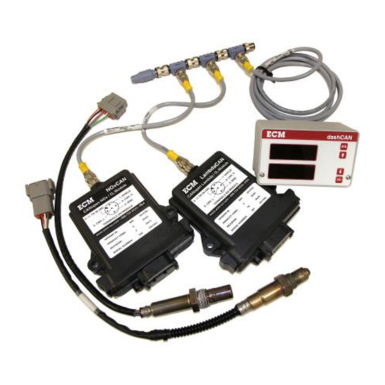
B. Module Stand-alone Mode and EIB Mode C. Calculating the %O in Air D. Interpreting Data from LambdaCAN* Modules E. Setting up ETAS INCA for ECM Modules F. Setting up ATI Vision for ECM Modules G. LOCKing and unLOCKing dashCAN*... - Page 4 Complex measurement systems can be easily built with ECM LambdaCAN*, NOxCAN*, and other modules. Here is a five- channel lambda, O , and NOx pressure-compensated in-vehicle system.
-
Page 5: Introduction
LambdaCAN or LambdaCANd before use (this is done by ECM when a P-comp kit is delivered with the LambdaCAN or LambdaCANd). See Appendix A for kit contents. The specifications for the kits are as follows: LambdaCANp Kit: Ranges: λ... - Page 6 LambdaCAN*, NOxCAN*, baroCAN, appsCAN) or analyzers (ex. NOx 5210, Lambda 5220, EGR 5230). While the tool is being used with modules, just ECM modules set to stand-alone mode (see Appendix B) should be connected to the CAN bus. While the tool is being used with analyzers, just analyzers should be connected to the CAN bus.
-
Page 7: Configuring A Module
Configuring a Module Normally, you will be configuring a module to be used in stand-alone mode. Stand-alone mode is used when the modules are connected to a CAN bus that goes directly to a data acquisition system. In stand-alone mode, a module’s configuration is performed by selecting one of the tasks in the “Task”... - Page 8 Change Node ID: Allowable range 0x01 to 0x7F (hex). When you assign a Node ID (NID), the following CAN IDs cannot be used by any other devices on the bus: 0x00, 0x80 + NID, 0x180 + NID, 0x280 + NID, 0x380 + NID, 0x480 + NID, 0x580 + NID, 0x600 + NID, 0x700 + NID, 0x7E4, 0x7E5.
-
Page 9: Calibration Of The Lambda Sensor
It is recommended that they be calibrated periodically during use. How often can only be determined by your experimentation. Alternatively, the sensors can be sent to ECM for recalibration. Calibration information (both factory calibration and user calibration) for the Lambda sensor is stored in a memory chip in the sensor’s connector. - Page 10 Delta O2 Table and Delta Lambda Table The %O2 calculated by LambdaCAN* modules is denoted as “O2R” and is a wet (i.e. water taken into consideration in %O2 calculation), at chemical-equilibrium (i.e. not frozen- equilibrium) %O2 measurement (see Appendix D). The Lambda (AFR, FAR, PHI) calculated by LambdaCAN* modules is denoted as “LAMR”...
- Page 11 Similarly, sometimes users would like Lambda (AFR, FAR, PHI) readings to match other instruments such as gas-bench analyzer calculated values (ex. via Spindt or Brettschneider) or company “heritage” Lambda measurement techniques. The Delta Lambda Table (found in the task “Lambda/O2 Delta Tables”) allows to user to add a number (a “delta”) to “LAMR” calculated by the LambdaCAN* module giving the “LAM”...
-
Page 12: Selecting What Data Is To Be Sent (Tpdos)
Selecting What Data is to be Sent (TPDOs) Data send from LambdaCAN* modules is packaged as TPDOs (Transmit Process Data Object). Each TPDO contains two pieces of data and each module can send up to four TPDOs. All selected TPDOs will be sent at the broadcast rate. For example, if the broadcast rate is 5 ms and four TPDOs were selected to be sent, then eight pieces of data would be transmitted every 5 ms. - Page 13 Pressure sensor measured pressure (absolute) in bar PPSI P(psi) Pressure sensor measured pressure (absolute) in psi PERF Pressure error bit flags Pressure sensor bit flags (LambdaCANp only) PERC CANopen error code ECM CANopen pressure error code (LambdaCANp only) Table 2: LambdaCAN* Parameter List...
-
Page 14: Producing A .Dbc File
Producing a .dbc File A .dbc file describes to the device receiving data from one or more LambdaCAN* modules what is in the data packages. For each module, the packages will contain data for the parameters selected in the activated TPDOs and an error code. The Configuration Software has a tool called “Generate .dbc…”... - Page 15 CAN recover bus off 0x00B5 CAN Tx CanId collision 0x00B6 Serial overrun 0x00FF Both ON Module powering down within 500ms Sensor Warm-up count down in seconds (active during ECM ECM AUX Error Code 0x0001) Table 3: LambdaCAN and NOxCAN* Error Codes List...
-
Page 16: Using The Dashcan* (Dashcan, Dashcan2, Dashcan+) Display
“T” (P/N 09-05). Simply attach dashCAN* to the CAN bus and parameters from two ECM *CAN modules can be displayed and converted to analog outputs (dashCAN2 or dashCAN+ only). The top display and half the analog outputs can be assigned to one module and the bottom display and the other half of the analog outputs can be assigned to the same or another module. - Page 17 When first entering SYS mode, either “MOd” will be on the top display or “LOCK” will be on the bottom display. If “MOd” is displayed, the and keys will roll through the setup options (see Table 4). First the options for the module assigned to the top display are shown on the top display, followed by identical options for the module assigned to the bottom display, ending with the global CONF (Configuration) setup.
-
Page 18: Mod (Module) Setup Option
MOd (Module) Setup Option In MOd setup, the serial number of the module assigned to the top or bottom display is entered. The serial number is written on a label on the module. The module assigned to the top display will be assigned the first half of the analog outputs. The module assigned to the bottom display will be assigned to the second half of the analog outputs. -
Page 19: Disp (Display) Setup Option
Here is an example of setting analog output 2 for a dashCAN+ (i.e. A2): 1. Press the SYS key so that “MOd” appears on the top display. 2. Press the key until “AOUT” is on the top display. Then press the ENT key. 3. - Page 20 1V4V (dashCAN2 and dashCAN+ only) “1V4V” commands the analog outputs to go to 1V then 4V. This is used to verify that the data acquisition system reading the analog outputs is correctly reading them. LOCK “LOCK” locks the MOd, RATE, AOUT, dISP, and LEdS setup. This stops unauthorized modification of the display.
-
Page 21: Using The Lambda Sensor Simulator
A properly operating LambdaCAN* module monitors lambda sensor condition and can calibrate the lambda sensor. An external pressure source is required to check out the pressure sensor. Lambda Sensor Simulators can be returned to ECM on a schedul e (1 year recommended) for recalibration. -
Page 22: Appendices
Appendix A: LambdaCAN* Kit Contents P/N 10-35 (LambdaCANp only) P/N 10-04 (LambdaCAN & LambdaCANd only) P/N 12-02... - Page 23 The LambdaCAN* Kit consists of: Description Quantity 1. LambdaCANp Control Module 02-08 or LambdaCANd Control Module 02-09 or LambdaCAN Control Module 02-01 2. LambdaCAN Sensor 05-01 (NTK 6mA) or Others Available 3. Lambda Sensor Extension Cable 10-02 (1m) 4. Flexi-Eurofast Cable 09-04 (0.3m) 5.
- Page 24 1. dashCAN (just dual display) 01-04 2. dashCAN2 (dual display, 2 analog outputs) 01-08 3. dashCAN+ (dual display 6 analog outputs) 01-05 Optional Sensor Simulator: 1. For LambdaCANp SIM700 For LambdaCANd and LambdaCAN SIM300 For a full list of options for LambdaCAN*, visit www.ecm-co.com...
-
Page 25: Module Stand-Alone Mode And Eib Mode
Appendix B: Module Stand-alone Mode and EIB Mode CAN data from LambdaCAN* modules can either be taken directly from the modules themselves or from the CAN port of display heads connected to the modules. When data is taken directly from one or more modules, each module must in Stand-alone mode. When data is taken from one or more display heads of a Lambda 5220, or EGR 5230 analyzer, each module must be in EIB mode. - Page 26 3. Slide the PCB out. Install a jumper on JP4. Jumper 4. Make sure both O-rings are on the threaded connector. 5. Slide the PCB into the enclosure until the two tangs “click”. 6. Put the nut on and tighten ONLY ½ turn from where it is seated. If this nut is tightened too much, the connector will crack and the enclosure will not be sealed.
- Page 27 P/N 11-02, DC Power Cable, To power Module Serial DB9F, Banana Plugs (shown), or P/N 11-01, DC Power Cable, Number DB9F, Spades “T” To CAN adapter Resistor On PC Figure A1: Module prepared for Reprogramming 8. Start the Configuration Tool (software). Click on the “Module”...
- Page 28 9. Click on the “Set to Stand-Alone Mode”. Wait for “Done” Message. Stop communication and exit program. The module is in Stand-alone mode. To convert a module from Stand-alone Mode to EIB Mode 1. Use the Configuration Tool (software) to “Set to EIB Mode”. 2.
-
Page 29: Calculating The %O
Appendix C: Calculating the %O in Air The Configuration Tool Software has a routine to calculate the %O in air. If the software is not available, the below may be used. The oxygen concentration in dry air (zero humidity) is 20.945 and decreases with increasing humidity. -
Page 30: Interpreting Data From Lambdacan* Modules
This fact is well documented in the literature. However, some organizations prefer to call their specific (and often unique) Spindt or Brettschneider calculations of Lambda the “true” values. To satisfy such needs, ECM has provided the Delta Lambda Table and Delta O2 Table features. - Page 31 Pressure compensation (P-comp) data is stored in the memory chip of every Lambda and NOx sensor. ECM offers P-comp kits for all of its LambdaCAN* kits. It is highly recommended that pressure compensation be used with any lean burn, HCCI, or...
- Page 32 Comparing to an ETAS LA4 Meter Many ETAS meters with new sensors will not correctly show the %O2 when the sensor is held in air. The actual %O2 in air depends on the humidity and will be almost always less than 20.945%.
-
Page 33: Setting Up Etas Inca For Ecm Modules
2. Connect the Ethernet port directly to the Ethernet port on your PC. This port does not use an internet/intranet connection like a router. 3. Connect either the CAN1 or CAN2 port to a CAN network (i.e. ECM modules or display heads). - Page 34 5. Configure the hardware. Click on the icon for the workspace you created in step 3. Open the Hardware Configuration icon under the section text “6. Hardware”. A hardware configuration window will open.
- Page 35 6. Select the hardware. In the hardware configuration window, right click the “HWK Workspace” listed under the section text “1. Hardware Devices”, and select Insert. Select the ETAS device you wish to use. In this example, we are using an ETAS ES591.1.
- Page 36 8. Initialize hardware. The hardware is currently stopped, as indicated by the red stop sign icon next to the selected hardware. You must initialize it before you can use it to collect data. Click on the Initialize Hardware button on the upper tool bar and wait for the hardware to complete its initialization.
- Page 37 10. Select and Configure Variables. Select the variables that you wish to monitor in the Experiment Environment. These variables names are based on the data found in the dbc file. Click Configure. 11. Another window will pop up to configure each selected variable. You can configure, for each variable, whether to record or simply display the data, how the data will be displayed (graphs, charts, gauges, numeric, etc.).
- Page 38 13. Start CAN monitoring. Right now there is no data displayed. That is because the CAN monitoring is stopped. To begin CAN monitoring, click on the Start Visualization icon (blue triangle) on the left hand tool bar. To stop CAN monitoring, click the Stop Measuring icon (black square) on the left hand tool bar.
-
Page 39: Setting Up Ati Vision For Ecm Modules
Introduction Connecting ECM LambdaCAN hardware to ATI VISION software is simple and does not require any third-party software interface. Using the ECM Configuration Tool software to produce a .dbc database file, and the ATI VISION CANMonitor interface, any available hardware CAN interface can be used to read LambdaCAN data. - Page 40 Creating a .dbc File The ECM Configuration Tool is used to create a .dbc database file for describing the CAN messages broadcast from the LambdaCAN. All ECM products with a CAN interface use the CANopen protocol at 500kHz by default. To generate a .dbc file using ECM Configuration Tool: 1.
- Page 41 ATI VISION CANMonitor provides a method of reading general purpose information from any available CAN channel. The .dbc file generated by the ECM Configuration Tool is used to describe the format of the information available to VISION. To setup a CANMonitor in ATI VISION: 1.
- Page 42 3. Add a physical hardware device by clicking Device Add Device, and select Kvaser CAN Channel. 4. Select a CANMonitor device by again clicking Device Add Device, and select CANMonitor.
- Page 43 5. Add the .dbc file generated from the ECM Configuration Tool to CANMonitor by clicking Device Add CAN Database and browsing to the previously created .dbc file. 6. Enable the hardware by clicking Project Online. The status of all of the devices should now show a Status of Online, and a value should appear in the Data Rate column of the Project window.
- Page 44 7. To view data, create a new Screen File and add a Control. Click File New Screen File 8. Select Object Add Control Gauge...
- Page 45 9. In the Select Data Items window open the CANMonitor file tree to view all of the available signals. Here the O2% from Node 0x10 has been selected. Click OK to add the Data Item to the Control. 10. Data should be visible on the gauge.
-
Page 46: Locking And Unlocking Dashcan
1. Press SYS until “LOCK” is displayed. Then press ENT. 2. “50” will be displayed. Press until “60” is displayed. Then press ENT. dashCAN is now unLOCKed. If an unauthorized person learns that 60 is the key number, contact ECM. - Page 47 Santa Clara, CA 95054 AND MONITORING Phone: (408) 734-3433 FAX: (408) 734-3432 Email: sales@ecm-co.com Web: www.ecm-co.com EC DECLARATION OF CONFORMITY We declare under our sole responsibility that the products: AFM1540 Lambda Module AFM1600L, AFM1600D Modules DIS1000 Display head EGR 4830 Analyzer...
- Page 50 Los Altos, CA 94023-0040 USA (408) 734-3433 Fax: (408) 734-3432 www.ecm-co.com...
Need help?
Do you have a question about the LambdaCAN Series and is the answer not in the manual?
Questions and answers