
Related Manuals for ECM appsCAN Module


Summary of Contents for ECM appsCAN Module
- Page 1 Module (accelerator pedal position simulator module) gpioCAN Module (general purpose input/output module) Instruction Manual 11-22-2009...
- Page 2 © COPYRIGHT 2009 by ECM: ENGINE CONTROL AND MONITORING. All Rights Reserved. No part of this manual may be photocopied or reproduced in any form without prior written consent from ECM: ENGINE CONTROL AND MONITORING. Information and specifications subject to change without notice.
-
Page 3: Table Of Contents
CONF (Configure) Setup Option (LEdS, LOCK) Appendices A. appsCAN Kit Contents B. Module Stand-alone Mode and EIB Mode C. Setting up ETAS INCA for ECM Modules D. LOCKing and unLOCKing dashCAN E. General Information F. Programming appsCAN via CAN messages... - Page 4 Complex measurement and control systems can be easily built with LambdaCAN, NOxCAN, NOxCANg, and appsCAN/gpioCAN modules.
-
Page 5: Introduction
However, during the product design process it was realized that with a few enhancements, the appsCAN module could be used as a general-purpose control and monitoring device. These enhancements were adopted and the appsCAN module is also sold as gpioCAN. -
Page 6: Analog I/O, Digital Outputs, And Other I/O
(programmed as a percentage of an input reference voltage, range 0 to 15V). 2. The programming of the mode of operation and the default (on power up) voltage or ratio is performed in the “Configure Analog Outputs” task of the ECM Configuration Tool [on CD]. - Page 7 Analog Inputs (VRF1, VRF2, VRF3, VRF4) Notes: 1. If an input reference voltage is not used for ratiometric mode, it is available as a general- purpose analog input. 2. To be used as a general-purpose analog input, a channel must have its “Enable Ratiometric”...
-
Page 8: Digital Outputs (Includes Pulse Output)
Digital Outputs (includes Pulse Output) Digital Outputs (PWM1, PWM2, PMW3, PWM4) Notes: 1. Digital outputs are programmable in 8 or 16-bit PWM resolution mode. In 8-bit mode, all four PWMs can be programmed. In 16-bit PWM resolution mode, only PWM2 and PWM4 can be programmed. -
Page 9: Other I/O
Other I/O Other I/O (AIN1, 5Vref, VEXC, GNDin) Notes: 1. AIN1 is an additional 0 to 5V analog input. 16 bits resolution. 2. 5Vref is a 5V reference voltage. 30 mA max. 3. VEXC is an output voltage source (approximately 9.3V) suitable for powering transducers. -
Page 10: Programming Outputs And Reading Inputs
Programming Outputs and Reading Inputs There are two ways to program the outputs and to read the inputs of an appsCAN module: via ECM’s Configuration Tool and via CAN messages sent by another program. Using ECM’s Configuration Tool The Configuration Tool runs on your PC and uses a CAN communication device to communicate with one or more modules. - Page 11 The Configuration Tool for an appsCAN module appears as shown below. On the bottom one-third of the screen either data from the module (TPDOs) or data to be sent to the module (RPDOs) is seen. To toggle between showing TPDOs and RPDOs, click on the “Data View”...
- Page 12 The Configuration Tool with its Task Menu pulled down appears below. A description of what the tasks do follows.
- Page 13 The pulse signal has a programmable delay (after pressing “Start” button) and pulse width. Before using this feature, the PWM output must be set to “Pulse Mode” in “Configure PWM Outputs”. Table 1: Task List for appsCAN Module...
-
Page 14: Data Sent To (Rpdo) And From (Tpdo) Module
TPDOs and RPDOs by clicking in its box to put in a check mark. Select the data contained in each TPDO and RPDO using the pull-down windows. The list of available parameters for the appsCAN module is given in Table 2. - Page 15 Circuit Board Temp (°C) Temperature of the module circuit board ERFL Error bit flags (bits) Module error flags (unsigned long format) ERCd ECM CANOpen Error Code ECM CANOpen Error Code VRF1 Voltage Reference 1 (V) Voltage measured at reference input 1 VRF2...
-
Page 16: Producing A .Dbc File
Producing a .dbc File A .dbc file describes to the device communicating from one or more appsCAN what is in the data packages. For each module, the packages will contain data for the parameters selected in the activated TPDOs, RPDOs, and an error code. The Configuration Software has a tool called “Generate .dbc…”... - Page 17 ECM ERROR CODE LED ACTION DESCRIPTION OF ERRORS 0x0000 Grn ON All OK, (green led constantly on) 0x0002 Grn/Both/Red 2s Power on reset/ Init hardware 0x00A1 Invalid software state 0x00B1 CAN overrun 0x00B2 CAN passive mode 0x00B3 CAN heartbeat error...
-
Page 18: Using The Dashcan Display
Using the dashCAN Display The dashCAN display (see cover and below) is a small (105 mm x 63 mm x 63 mm), two- channel remote display for CAN networks containing appsCAN, LambdaCAN and NOxCAN(g) modules. dashCAN comes with a two meter cable and a “T” (P/N 09-05). Simply attach dashCAN to the CAN bus and any two parameters being transmitted from modules can be displayed. -
Page 19: Mod (Module) Setup Option
Setup Option Level 1 Function Select module s/n. Default is NONE. RATE Set parameter averaging rate. Range 0.001 to 1.000 Default is 1.000 dISP Select parameter. Note: Parameters available are those programmed using Configuration Software. CONF LEdS Set display intensity. Default is 3333. LOCK Lock and Unlock Display for Programming MOd, RATE, and dISP appear on the upper display for the upper channel and on the lower... -
Page 20: Disp (Display) Setup Option
dISP (Display) Setup Option In dISP setup, the parameters to be displayed are selected. Only parameters selected to be transmitted by the Configuration Software can be displayed. Here is an example of setting the parameter to be displayed on the upper display: 1. -
Page 21: Appendices
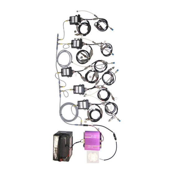
Appendix A: appsCAN Kit Contents... - Page 22 The appsCAN Kit consists of: Description Quantity 1. appsCAN Control Module 02-05 2. Left (gray) connector with 300mm pigtails 11-22 3. Right (black) connector with 300mm pigtails 11-23 4. Flexi-Eurofast Cable 09-04 (0.3m) 5. Eurofast “T” 09-05 6. Eurofast Terminating Resistor 09-06 7.
-
Page 23: Module Stand-Alone Mode And Eib Mode
Appendix B: Module Stand-alone Mode and EIB Mode CAN data from LambdaCAN and NOxCAN(g) modules can either be taken directly from the modules themselves or from the CAN port of display heads connected to the modules. When data is taken directly from one or more modules, each module must in Stand-alone mode. When data is taken from one or more display heads of an EGR 5210, Lambda 5220, or EGR 5230 analyzer, each module must be in EIB mode. - Page 24 3. Slide the PCB out. Install a jumper on JP4. Jumper 4. Make sure both O-rings are on the threaded connector. 5. Slide the PCB into the enclosure until the two tangs “click”. 6. Put the nut on and tighten ONLY ½ turn from where it is seated. If this nut is tightened too much, the connector will crack and the enclosure will not be sealed.
- Page 25 P/N 11-02, DC Power Cable, To power Module Serial DB9F, Banana Plugs (shown), Number P/N 11-01, DC Power Cable, “T” To CAN adapter Resistor On PC Figure A1: Module prepared for Reprogramming 8. Start the Configuration Tool (software). Click on the “Module” tab. Select the CAN adapter being used.
- Page 26 9. Click on the “Set to Stand-Alone Mode”. Wait for “Done” Message. Stop communication and exit program. The module is in Stand-alone mode. To convert a module from Stand-alone Mode to EIB Mode 1. Use the Configuration Tool (software) to “Set to EIB Mode”. 2.
-
Page 27: Setting Up Etas Inca For Ecm Modules
2. Connect the Ethernet port directly to the Ethernet port on your PC. This port does not use an internet/intranet connection like a router. 3. Connect either the CAN1 or CAN2 port to a CAN network (i.e. ECM modules or display heads). - Page 28 5. Configure the hardware. Click on the icon for the workspace you created in step 3. Open the Hardware Configuration icon under the section text “6. Hardware”. A hardware configuration window will open.
- Page 29 6. Select the hardware. In the hardware configuration window, right click the “HWK Workspace” listed under the section text “1. Hardware Devices”, and select Insert. Select the ETAS device you wish to use. In this example, we are using an ETAS ES591.1.
- Page 30 8. Initialize hardware. The hardware is currently stopped, as indicated by the red stop sign icon next to the selected hardware. You must initialize it before you can use it to collect data. Click on the Initialize Hardware button on the upper tool bar and wait for the hardware to complete its initialization.
- Page 31 10. Select and Configure Variables. Select the variables that you wish to monitor in the Experiment Environment. These variables names are based on the data found in the dbc file. Click Configure. 11. Another window will pop up to configure each selected variable. You can configure, for each variable, whether to record or simply display the data, how the data will be displayed (graphs, charts, gauges, numeric, etc.).
- Page 32 13. Start CAN monitoring. Right now there is no data displayed. That is because the CAN monitoring is stopped. To begin CAN monitoring, click on the Start Visualization icon (blue triangle) on the left hand tool bar. To stop CAN monitoring, click the Stop Measuring icon (black square) on the left hand tool bar.
-
Page 33: Locking And Unlocking Dashcan
2. “50” will be displayed. Press ↑ until “60” is displayed. Then press ENT. dashCAN is now unLOCKed. If an unauthorized person learns that 60 is the key number, contact ECM. Appendix E: General Information Voltage Input: 11 to 25 VDC @ 250 mA Terminal Assignments on Eurofast Connector: 1. -
Page 34: Programming Appscan Via Can Messages
(NID). The allowable range for the NID is 0x01 to 0x7F. When connecting other non-ECM devices on the same CAN bus, ensure that the following CANids are not used:... - Page 35 0x81 lo byte 0x00 0x00 lo byte = ECM Error Code (0x00 = Data valid, see Table 3 in “Producing a .dbc File” section) iii) TRANSMIT PROCESS DATA OBJECT [TPDO] (Broadcast rate = 0.005sec, DLC=8) TPDO1 CAN id byte 0...
- Page 36 Sent to (RPDO) and from (TPDO) Module” section contains a list of all available TPDO parameters. Each module can transmit up to four TRANSMIT PROCESS DATA OBJECTS (TPDO) at the programmed TPDO broadcast rate (see Section 6.7 to determine minimum broadcast rate).
- Page 37 IEEE-754 standard. All RPDO data is transmitted on the CAN bus least significant byte first (Intel format). The NID and RPDO mapping can be changed by the user. Example: The following data was sent to the module with NID = 0x10 on RPDO1 and contains 2 PDOs, AO1V and PWM1.
- Page 38 Writing to the appsCAN Module (SDO Write) Configuration of the appsCAN module is performed by writing to the Object Dictionary (OD) and by issuing ECM CANopen OS Commands (OS Command). Both of these actions are implemented using a Service Data Object Expedited Write (SDO Write). The format is as...
- Page 39 Reading from the appsCAN Module (SDO Read) During configuration, it may be necessary to read certain locations in the Object Dictionary (OD). This can be done with a Service Data Object (SDO) Read. The format for a (SDO Read) is as follows:...
- Page 40 Identifying the appsCAN Module Each appsCAN module can be uniquely identified by reading the following four parameters in the OD: Vendor ID (0x000001C6) located at OD address 0x1018, subindex 0x01 (4 byte integer/unsigned 32) Product Code (appsCAN = 0x00000009) located at OD address 0x1018...
- Page 41 Commands to the appsCAN Module 6.1. Configure Activation of RPDOs Send the following OS Command to configure the module to act on RPDOs immediately after they are sent. CANid byte 0 byte 1 byte 2 byte 3 byte 4 byte 5...
- Page 42 Example: Configure all analog channels as a ratiometric output of the reference. CANid byte 0 byte 1 byte 2 byte 3 byte 4 byte 5 byte 6 byte 7 0x600+NID 0x2F 0x23 0x50 0x00 0x0F Setting Default Output Values Default analog output values are stored as single precision floating point numbers (IEEE- 754) in the module.
- Page 43 6.4. Configure PWM Outputs (PWM1, PWM2, PWM3, PWM4) Select Output Type There are three possible settings for each PWM output: pull-up resister, polarity, and pulse mode. These settings are controlled by a 16-bit register that can be accessed by performing an SDO read or write to OD address 0x5024, subindex 0x00.
- Page 44 6.5. Configure Pulse Mode Outputs These configurations only apply if the PWM output is configured as Pulse Mode (see Section 6.4 Configure PWM Outputs). Polarity and pull-up resister enables still apply in pulse mode. There are three registers required to initiate a pulse signal: delay, pulse width, and status. The configurations for pulse mode are located at the following Object Dictionary entries.
- Page 45 The Node ID (NID) can be programmed from 0x01 to 0x7F (1 to 127). To change the NID, several messages must be sent to the appsCAN module. This must be followed by a reset of the module (that can be performed three different ways; see the following).
- Page 46 The last message sent takes the module out of configuration mode. CAN id byte 0 byte 1 0x7E5 0x04 0x00 After the NID has been successfully changed, the module enters pre-operational mode and does not broadcast data. The module can be returned to broadcast mode 1 of 3 ways: i) Power-cycle the module by disconnecting and reconnecting the power.
- Page 47 CAN bus and how many TPDOs have been enabled for each module. If the broadcast rate is too fast the ECM Configuration Tool will not be able to identify or configure any of the modules. The formula for calculating the minimum broadcast rate is as follows: Minimum Broadcast Rate (ms) >...
- Page 48 6.8. Enable Transmit Process Data Object (TPDO) There are four TPDOs; each can be individually enabled to transmit the mapped PDO data at the broadcast rate. The following OD addresses are required to enable each TPDO. TPDO EnableOD Transmit Address CANid TPDO1 0x1800...
- Page 49 Example: Enable TPDO1 for the module with NID = 0x10, (EnableOD Address = 0x1800, Transmit CANid = 0x180 + 0x10 = 0x190). CANid byte 0 byte 1 byte 2 byte 3 byte 4 byte 5 byte 6 byte 7 0x620 0x23 0x00 0x18...
- Page 50 Enter the number of PDOs in the TPDO by performing a SDO Write as follows: CANid byte 0 byte 1 byte 2 byte 3 byte 4 byte 5 byte 6 byte 7 0x600+NID 0x2F ConfigOD ConfigOD 0x00 0x02 Address lo Address hi Example: Map the PDO for AIN1 (V) and VRF3 (V) to TPDO2 for the module with NID = 0x02.
- Page 51 6.12. Disable Receive Process Data Object (RPDO) The following OD addresses are required to disable each RPDO. RPDO EnableOD Receive Address CANid RPDO1 0x1400 0x200 + NID RPDO2 0x1401 0x300 + NID RPDO3 0x1402 0x400 + NID RPDO4 0x1403 0x500 + NID To disable a RPDO, perform a SDO Write to the Enable OD Address for that particular RPDO as follows: CANid...
- Page 52 0x16 0x00 0x02 6.14. Factory Reset Parameters that are stored in non-volatile memory (EEprom) can be reset to a standard configuration by issuing the ECM OS Command 0xDF (see Appendix B). CANid byte 0 byte 1 byte 2 byte 3...
- Page 53 ECM CANopen OS Commands A user-specific CANopen OS Command to the appsCAN module is sent using an SDO expedited write message in the following form. These commands apply only to the appsCAN module and are listed on the following page:...
- Page 54 VALUE REPLY DESCRIPTION COMMAND ResetAllFilters 0x15 Resets alpha for recursive average to factory values 0x00 defAlphaOK ExpertModeDisable 0x16 None This command removes the unit from expert mode. NoUpdateCanIdsOnNewNodeId0x17 None 0x18 None UpdateCanIdsOnNewNodeId ResetTPDOs 0x1F None Set all TPDOs as delivered from factory.
- Page 55 Heartbeat A Heartbeat message is transmitted every 0.5 seconds by the appsCAN module. During normal operation the module is in operational mode (NMT state = 0x05). CAN id byte 0 byte 1 byte 2 byte 3 byte 4 byte 5...
- Page 57 586 Weddell Drive, Suite 2 Sunnyvale, CA 94089-2134 AND MONITORING Phone: (408) 734-3433 FAX: (408) 734-3432 Email: sales@ecm-co.com Web: www.ecm-co.com EC DECLARATION OF CONFORMITY We declare under our sole responsibility that the products: AFM1540 Lambda Module AFM1600 Lambda and O Analyzer DIS1000 Display head...
- Page 60 Los Altos, CA 94023-0040 • USA • (408) 734-3433 • Fax: (408) 734-3432 • www.ecm-co.com...
Need help?
Do you have a question about the appsCAN Module and is the answer not in the manual?
Questions and answers