
Subscribe to Our Youtube Channel
Related Manuals for Fronius Virtual Welding 2.0


Summary of Contents for Fronius Virtual Welding 2.0
- Page 1 Operating Instructions Virtual Welding 2.0 EN-US Operating instructions 42,0426,0089,EA 015-24012023...
-
Page 3: Table Of Contents
Table of contents Safety Instructions Explanation of Safety Instructions General Environmental conditions Obligations of the operating company Obligations of personnel Mains connection Danger from mains current EMC device classifications Particular hazard areas Safety measures at the setup location and during transport Safety measures in normal operation Maintenance and repair Safety symbols... - Page 4 Training concept and procedure for commissioning Training concept Commissioning procedure First step of commissioning: Create a curriculum General Configuring the USB thumb drive Creating a knowledge check Saving content to the USB thumb drive Importing content Merging content into a curriculum Second step of commissioning: create a course Using a course Creating a course...
- Page 5 Quiz Function Activating/deactivating a quiz, importing/exporting a quiz Exporting a quiz Creating a Quiz Importing a quiz Setup Menu Permissions and accessing the Setup menu Different permissions Accessing the Setup menu Network menu item Description Creating cluster networking Other settings menu item Displaying the license list Creating a backup (exporting data) Management code...
-
Page 6: Safety Instructions
Safety Instructions Explanation of DANGER! Safety Instruc- tions Indicates an immediate danger. ▶ Death or serious injury may result if appropriate precautions are not taken. WARNING! Indicates a possibly dangerous situation. ▶ Death or serious injury may result if appropriate precautions are not taken. CAUTION! Indicates a situation where damage or injury could occur. -
Page 7: Environmental Conditions
Environmental Operation or storage of the device outside the stipulated area will be deemed as conditions not in accordance with the intended purpose. The manufacturer accepts no liab- ility for any damage resulting from improper use. Installation and operation may only take place within closed and dry rooms. Temperature range of ambient air: During operation: - 10 °C to + 35 °C (14 °F to 95 °F) During transport and storage: - 25 °C to + 55 °C (- 13 °F to 131 °F) -
Page 8: Danger From Mains Current
Danger from An electric shock can be fatal. mains current Do not touch voltage-carrying parts inside or outside the device. All cables and leads must be secured, undamaged, insulated, and adequately di- mensioned. Replace loose connections and scorched, damaged, or inadequately dimensioned cables and leads immediately. -
Page 9: Particular Hazard Areas
If this is the case, then the operating company is obliged to take appropriate ac- tion to rectify the situation. Check and evaluate possible problems and the interference immunity of equip- ment in the vicinity according to national and international regulations. For ex- ample, from: Safety devices Mains power lines, signal lines, and data transfer lines... -
Page 10: Safety Measures At The Setup Location And During Transport
Safety measures Take care to ensure that the applicable national and regional guidelines and acci- at the setup loc- dent prevention regulations are observed when transporting the device. espe- ation and during cially guidelines concerning hazards during transport and shipment. transport Only carry out the transport in the original packaging. -
Page 11: Data Backup
Copyright Copyright of these Operating Instructions remains with the manufacturer. Text and illustrations were accurate at the time of printing. Fronius reserves the right to make changes. The contents of the Operating Instructions shall not provide the basis for any claims whatsoever on the part of the purchaser. If you... -
Page 13: General Information
General information... -
Page 15: General
General Device concept Virtual Welding is used for the realistic learning of welding skills. Virtual Weld- ing offers the following benefits: Very low cost of training. No con- sumables are required (wire elec- trodes, welding gas, etc.) The trainees are not exposed to the dangers of welding (heat, weld- ing fumes, welding spatter, noise, etc.) -
Page 16: Intended Use
Intended use The device is to be used exclusively for its intended purpose. The device is intended for welding simulation only with the software and hard- ware supplied by the manufacturer. Utilization for any other purpose, or in any other manner shall be deemed im- proper. -
Page 17: Software And Product Updates
Incorrect operation and incorrectly performed work can cause serious injury and property damage. Installation, repair, and maintenance work may only be carried out by trained personnel. The following documents must be read in full and un- derstood: These Operating Instructions All system component Operating Instructions, especially the safety rules Dispose of old devices in accordance with safety rules and not in normal domest- ic waste. -
Page 18: Scope Of Supply And Optional Function Packages
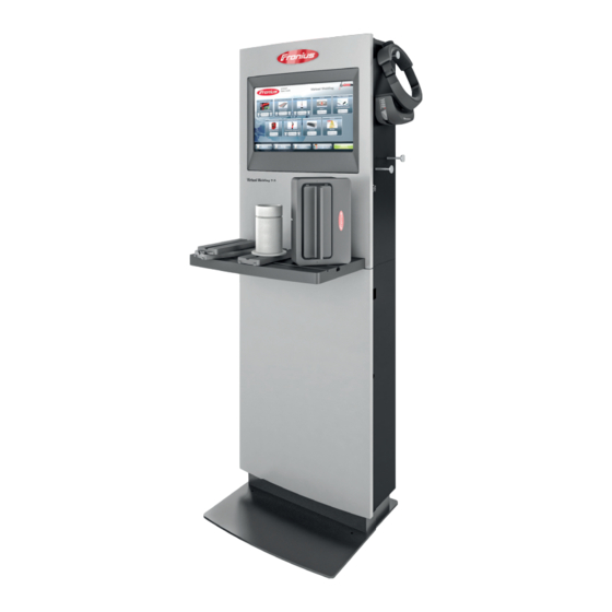
Scope of supply and optional function packages Scope of supply In addition to StandUp Terminal or the MobileCase, the following system com- ponents are included in the scope of supply: Work table Workpiece holder Single-V butt weld workpiece, layer 1 (square butt weld) Fillet weld workpiece Single-V butt weld workpiece, layer 2 and 3... -
Page 19: Function Packages
Pipe workpiece 2 NFC keys In addition to the supplied StandUp Terminal, but not shown: 3D glasses 4 keys 4 M8 x 80 mm screws with washers, for screwing together the upper and lower parts Mounting bracket including 4 M8x16 mm screws and washers This document Mains cable (for connecting to a socket) Cable for 3D glasses... - Page 20 MMA function package...
-
Page 21: Operating Controls, Connections And Mechanical Components
Operating controls, connections and mechanical components... -
Page 23: Touch Screen And Sensor
Touch screen and sensor Touch screen and sensor Touch screen and sensor on the StandUp Ter- Sensor on MobileCase minal The touch screen (1) allows for intuitive touch operation. The sensor (2), in conjunction with the supplied NFC keys, performs the following functions: Touch the sensor with NFC key once = Access terminal management to create curricula, for example - also see sec-... -
Page 24: Operating Controls And Connections
Operating controls and connections Connections on Connection for the workpiece the StandUp Ter- holder minal For connecting the sensor cable from the workpiece holder Connection for Robotics-Clip or filler material For connecting the sensor cable from the Robotics-Clip; For connecting the sensor cable from the filler material (TIG) Connection 1 for welding torch For connecting the sensor cable... -
Page 25: Mobilecase Operating Controls And Connections
LAN connection For connecting a LAN network cable External display connection (5) (6) (7) (8) (9) For connecting an external monitor or projector (after con- necting the monitor/projector, restart the Virtual Welding sys- tem) USB port For connecting the 3D glasses data cable 3D glasses supply 3D glasses connection (display... - Page 26 LAN connection For connecting a LAN network cable Connection 1 for welding torch For connecting the control cable from the welding torch For connecting the control cable from the electrode holder Connection 2 for welding torch For connecting the sensor cable from the welding torch For connecting the sensor cable from the electrode holder Connection for Robotics-Clip or filler material For connecting the sensor cable from the Robotics-Clip...
-
Page 27: Position Of The Ventilation Openings
Position of the ventilation openings Ventilation Ventilation openings at the openings on the front of the device StandUp Termin- Ventilation openings at the rear of the device Ventilation Ventilation openings at the openings on the front of the device MobileCase... - Page 28 Ventilation openings at the rear of the device...
-
Page 29: Installation
Installation... -
Page 31: Before Installation And Initial Operation
Before installation and initial operation Safety WARNING! Danger from incorrect operation and work that is not carried out properly. This can result in severe personal injury and damage to property. ▶ All the work and functions described in this document must only be carried out by trained and qualified personnel according to valid national and inter- national standards. - Page 32 Protect the device from severe environmental impact, such as: Dust and dirt build-up Rain and moisture Strong magnetism or radio waves Cold Ensure that the permissible environmental conditions are maintained at all times. For more information on the permissible environmental conditions, see section Environmental conditions on page 7.
-
Page 33: Installing The Standup Terminal
Installing the Standup Terminal Safety WARNING! Danger from electrical current. This may result in serious injuries or death. ▶ Before starting work, switch off the device and disconnect it from the mains. ▶ Secure the device to prevent it from being switched back on again. WARNING! Danger from incorrect installation. - Page 34 Top of StandUp Terminal, side view (2) = mounting bracket (3) = screws with washers...
-
Page 35: Assemble And Screw In The Standup Terminal
Assemble and Place the bottom part in its final screw in the setup location (3) (3) (3) (3) StandUp Termin- To do so, make sure that the mounting brackets (2) extend to the wall Place the top part on the bottom part Screw the two parts together using the 4 M8 x 80 mm Allen screws (1) - Page 36 Loosen the screws (5) while holding one of the brackets (6) Guide the brackets (6) down until the screws (5) can be screwed through the holes (7) Fasten the screws (5) Standard mounting of tool table: Push the tool table (8) fully into the opening (9) Overhead mounting of tool table:...
- Page 37 NOTE! For better visibility, the mounting brackets for wall mounting have been re- moved in the following images. However, the StandUp Terminal must always be screwed to the mounting brackets on the wall. ▶ For information on the mounting brackets, see section Screw the mounting bracket to the StandUp Terminal.
-
Page 38: Waiting Time Until The Power Connection Is Established
CAUTION! Danger from falling tool table. Personal injury and damage to property may result. ▶ Always make sure the tool table is locked in the brackets (10) and (11) as shown above. Waiting time un- CAUTION! til the power connection is es- Risk of poor acclimatization of components by connecting the device to the grid tablished too early... -
Page 39: Installing The Mobilecase
Installing the MobileCase Safety WARNING! Danger from electrical current. This may result in serious injuries or death. ▶ Before starting work, switch off the device and disconnect it from the mains. ▶ Secure the device to prevent it from being switched back on again. WARNING! Danger from incorrect installation. -
Page 40: Waiting Time Until The Power Connection Is Established
Push the tool table (2) fully into the opening (1) Refer to the Installation Instructions of the relevant assembly kit for the overhead mounting of the tool table CAUTION! Risk of poor acclimatization of components by connecting the device to the mains too early. -
Page 41: Fitting/Connecting The System Components
Fitting/connecting the system components Installing and connecting the tool table and other system components NOTE! The position of the workpiece holder (1) shown corresponds to the standard mounting position. The workpiece holder (1) can be mounted in other positions on the tool table. These are shown at the end of the section. Place the workpiece holder (1) on the tool table To do so, make sure that the workpiece holder is locked in the guides (2) Connect the workpiece holder sensor cable to the Virtual Welding system... - Page 42 Insert the desired workpiece into the workpiece holder as shown above Connect the 3D glasses to the Virtual Welding system Connect the welding torch / electrode holder to the Virtual Welding system For more information on the connections Connections on the StandUp Terminal on the StandUp Terminal, see section from page on the MobileCase see section...
- Page 43 Alternative mounting positions of workpiece holder 1: Insert the projection (3) into the recess (4) on the tool table Alternative mounting positions of workpiece holder 2: Insert the projection (5) into the recess (4) on the tool table CAUTION! Risk of falling workpiece holder. Personal injury and damage to property may result.
-
Page 44: Powering On, Initial Steps
Powering on, initial steps Plug in the mains WARNING! cable and turn on the device Danger from electrical current. This may result in serious injuries or death. ▶ Only use the supplied mains cable to connect to the mains. ▶ Only connect the mains cable to a properly grounded socket. -
Page 45: Commissioning
Commissioning... -
Page 47: Training Concept And Procedure For Commissioning
Course B is assigned to the systems used for advanced training Commissioning Create a curriculum and chapters procedure This step is only necessary if Fronius licenses were purchased with the Virtual Welding system If Fronius licenses have been purchased with the system, ready-made curricula are pre-installed on the system... -
Page 48: First Step Of Commissioning: Create A Curriculum
First step of commissioning: Create a curriculum General A curriculum only needs to be created if Fronius licenses were purchased with the Wirtual Welding system. If you purchased Fronius licenses with the system, this section can be skipped and the course preparation is the first step of commissioning. To do... -
Page 49: Creating A Knowledge Check
Select button (3) to configure the USB thumb drive Creating a know- The knowledge check is part of course mode and is used to check whether ledge check the learned theory content has been understood. It is recommended to only include questions that are answered by the theor- etical content provided in the knowledge check. - Page 50 Select button (1) Fill in the text fields (2) - (6) for the first question of the knowledge check Select button (7) to add another question Repeat these steps as many times as desired NOTE! It is recommended that the knowledge check be given a practical and unique file name when saving, since this file name can be transferred to the Virtual Welding system during a later import (this means that the name of the know- ledge check does not have to be re-entered on the Virtual Welding system).
-
Page 51: Saving Content To The Usb Thumb Drive
Select button (8) and save the knowledge check in the „know- ledgecheck“ folder on the USB thumb drive Saving is only possible if all fields in the QuizEditor are filled in If desired, a quiz can also be created. To do so, see section Quiz from page 101. -
Page 52: Importing Content
Copy all desired learning content to the "theory" folder Use PDF only Copy customer-specific WPS into the "wps" folder WPS from Fronius are already installed on the system The knowledge check created in the previous step is already in the "know- ledgecheck" folder The "quiz"... - Page 53 To import theory content: Select the desired file, for example (4) Select button (5) To import theory content: Make sure the correct welding process is selected (6) Select checkbox (7) to accept the original file name Select button (8) to import the file...
- Page 54 (10) (11) To import the knowledge check: Select button (9) Select tab (10) Select button (11) (12) (13) To import the knowledge check: Select the desired file, for example (12) Select button (13)
- Page 55 (15) (14) (16) To import the knowledge check: Make sure that the correct welding process is selected (14) Select checkbox (15) to accept the original file name Select button (16) to import the file (18) (19) (17) To import WPS: Select button (17) Select tab (18) Select button (19)
- Page 56 (20) (21) To import WPS: Select the desired file, for example (20) Select button (21) (23) (22) (24) To import WPS: Make sure the correct welding process is selected (22) Select checkbox (23) to accept the original file name Select button (24) to import the file Insert the USB thumb drive into the system For example, the USB thumb drive can be used to store curricula on it (backup copy)
-
Page 57: Merging Content Into A Curriculum
Merging content In the following section, the previously imported content is merged into a into a curriculum curriculum. The curriculum can be divided into individual chapters as desired It is recommended that these chapters have a progressive structure. For example, a chapter with easy welding tasks and corresponding additional contents, a chapter with medium-difficulty welding tasks and corres- ponding additional contents, etc. - Page 58 Select which content types are to be inserted in the chapter (4) Depending on requirements, you can select individual content types or all content types Select button (5) In the next steps, the individual contents are inserted in the chapter To insert training into the first chapter: (Only possible if this content type was selected when creating the chapter) (11)
- Page 59 (13) (13) (12) (14) Enable/disable the required tasks using the buttons (12) If a task is enabled, it can be disabled again during the course creation If a task is disabled, the task in that curriculum will not be enabled later Use the arrow keys (13) to select, how large the acceptable deviation from the specification (Ghost) may be (for more information on the Ghost , see section...
- Page 60 (17) (16) Make sure the correct welding process is selected If necessary, select the button (16) to change the welding process Select button (17) to insert the desired WPS into the chapter To insert theory content into the first chapter: (Only possible if this content type was selected when the chapter was created) Make sure the correct welding process is selected If necessary, select the button (6) to change the welding process...
- Page 61 Make sure the correct welding process is selected If necessary, select the button (6) to change the welding process Select button (7) to insert the desired knowledge check into the chapter Each chapter can contain only one knowledge check (10) Select what percentage of knowledge check questions need to be answered correctly in order to positively complete the knowledge check (8) A value of 80% or more is recommended...
- Page 62 (18) Give this chapter a name Select button (18) To complete the curriculum creation: (20) (19) Select button (19) to complete the curriculum creation A new chapter can be added to the curriculum at this point (optional). In this case, select the button (20) and repeat the previous steps...
- Page 63 (21) Give the curriculum a name Select button (21) (22) The new curriculum is displayed in the overview (22)
-
Page 64: Second Step Of Commissioning: Create A Course
Second step of commissioning: create a course Using a course Individual courses for the desired group of trainees can be compiled from the curriculum. If there are multiple Virtual Welding systems in a network, the courses can be assigned to different Virtual Welding systems, for example: Course A is assigned to the systems used for basic training Course B is assigned to the systems used for advanced training Creating a... - Page 65 If necessary, select the button (6) to change the welding process Select a curriculum to use as the basis for the course. For example (9) Fronius curricula are displayed under the tab (7) Self-created curricula are shown under the tab (8)
- Page 66 (13) Give the course a name Select button (13) The new course appears in the course overview After creating all the desired courses, it is recommended that you back up your Creating a backup (exporting data) data. For more information, see section from page 114.
-
Page 67: Third Step Of Commissioning: Assign Courses
Third step of commissioning: assign courses Assigning With the NFC key, touch the sensor on the Virtual Welding system to open courses to the terminal management Virtual Welding For the position of the sensor, see section Touch screen and sensor system page Select button (1) -
Page 68: Assigning Courses To Multiple Terminals
Select button (6) The course has been assigned to the terminal Assigning If multiple Virtual Welding systems are in use, it is possible to combine them courses to mul- into groups (Cluster networking) tiple terminals See section Creating cluster networking from page for the description of creating groups... -
Page 69: Fourth Step Of Commissioning: Enable Course Mode, Prepare The System For Users
Fourth step of commissioning: enable course mode, prepare the system for users Activating With the NFC key, touch the sensor on the Virtual Welding system to open course mode terminal management For the position of the sensor, see section Touch screen and sensor page Select button (1) Select tab (2) -
Page 71: Ghost
Ghost... -
Page 73: Explanation And Configuration Options
Explanation and configuration options Explanation The Ghost is a virtual welding torch that is displayed in the welding tasks The Ghost shows the ideal movement when welding A Ghost is stored for all welding tasks as standard (standard Ghost) The Ghost button (1) allows you to create a variable Ghost A variable Ghost can be created in addition to the standard Ghost and adap- ted to your own requirements A variable Ghost can be created for all welding processes... - Page 74 Use the arrow keys to make the desired settings Select button (4) Select button (5)
- Page 75 Assign a name for the variable Ghost Select button (6) Follow the additional instructions on the touch screen NOTE! In Virtual Welding Robotics, the ghost creation distinguishes between Polygon and Cycles: ▶ Polygon: Allows for recording of a completely free path movement (lettering, etc.) ▶...
-
Page 77: Available Modes On The Virtual Welding System
Available modes on the Virtual Welding system... -
Page 79: Course Mode
Course mode Explanation In course mode, you can easily adapt or configure courses with varying levels of difficulty. The courses and the underlying curricula are easy to access. The res- ults are comparable with the help of ranking lists, which allows for a precise re- sponse to the needs of the trainee welder. -
Page 80: Profile
Profile To be able to use course mode properly, a profile must be created for each user. Therefore, it is recommended to create a profile for each user. A profile allows you to perform the following actions: Saving of data for each individual user (trainees) Follow-up of the last welding results of each individual user An overview of the current ranking list placements for each user To create a profile:... - Page 81 Select button (3) Enter required data Read and understand the text next to the checkbox (4) and select the check- box (4) Select button (5) Confirm the displayed message...
-
Page 82: Ranking List Description, Exporting Course Data
Once the settings have been completed, the profile of the respective user can be called up using the button (6) Ranking list de- Each course has its own ranking list scription, ex- The ranking list enables comparison of the individual welding results with the porting course welding results of the other participants (all available Virtual Welding sys- data... - Page 83 Select button (1) Select tab (2) Make sure the correct welding process is selected If necessary, select the button (3) to change the welding process Select button (4) next to the desired course Select button (5) Course data are stored on the USB thumb drive...
-
Page 84: Open Mode
Open mode Explanation Open mode is used to demonstrate the Virtual Welding system All available welding parameters and exercises can be freely selected without a teaching concept Points earned will not be saved In open mode, the following functions are available: Free training (practical welding tasks) Quiz - for more information, see section Quiz... -
Page 85: Showroom Mode
Showroom mode Explanation Showroom mode has the smallest range of functions of all the modes, mak- ing it ideal for operation without an operator, such as in entrance halls In showroom mode, only open training can be selected Activating show- With the NFC key, touch the sensor on the Virtual Welding system to open room mode terminal management... -
Page 87: Calibration
Calibration... -
Page 89: Room Calibration
Room calibration Function Room calibration calibrates the tracking of the 3D glasses (optical calibra- tion) Room calibration ensures that the 3D glasses function properly Room calibration must always be carried out when starting for the first time and when the Virtual Welding system is changed to a different location Performing room NOTE! calibration... - Page 90 Select button (2) Select tab (3) Select button (4) Follow the instructions on the touch screen / glasses...
-
Page 91: System Calibration
System calibration Function The system calibration is the calibration of the magnetic sensors in the indi- vidual system components (workpiece, welding torch, etc.) During system calibration, the positions of the individual components are compared with each other System calibration must always be carried out when starting for the first time and when the Virtual Welding system is changed to a different location Performing sys- With the NFC key, touch the sensor on the Virtual Welding system to open... - Page 92 Select the welding process for which system components are to be calibrated Follow the instructions on the touch screen...
-
Page 93: Changing The Camera Setting
Changing the camera setting Function The camera setting is used to adjust the Zoom- factor Depending on your preference, this setting can be used to move the dis- played image closer or farther away Changing the With the NFC key, touch the sensor on the Virtual Welding system to open camera settings terminal management For the position of the sensor, see section... - Page 94 Select the desired welding process Follow the on-screen instructions...
-
Page 95: Component Calibration
Component calibration Function Component calibration compares the data of the system calibration (= calib- ration of magnetic sensors) and the room calibration (= calibration of the cameras of the 3D glasses) Component calibration is started automatically before each training session if required Performing com- With the NFC key, touch the sensor on the Virtual Welding system to open... - Page 96 Select the welding process for which system components are to be calibrated Follow the instructions on the touch screen...
-
Page 97: Other Settings
Other settings... -
Page 99: License Management
License management Function System-relevant information is displayed in license management, such as: Hardware-Dongle serial number Installed licenses etc. Additional Virtual Welding licenses can also be installed in license management, for example to enable additional welding processes. Opening license With the NFC key, touch the sensor on the Virtual Welding system to open management terminal management For the position of the sensor, see section... -
Page 100: Changing The Robot Manufacturer
Changing the robot manufacturer Description The robot manufacturer can be set with a corresponding license. This shows the arm of the robot manufacturer during robotic welding. With the NFC key, touch the sensor on the Virtual Welding system to open terminal management Touch screen and sensor For the position of the sensor, see section... -
Page 101: Quiz
Quiz Function The quiz is a fun knowledge check, the results are not saved The quiz is only available in open mode For more information on open mode, see section on page The system includes a quiz containing 70 questions as standard Activating/deac- With the NFC key, touch the sensor on the Virtual Welding system to open tivating a quiz,... -
Page 102: Creating A Quiz
Select button (1) Select tab (2) Select button (3) Select tab (4) Select button (5) to export the pre-installed quiz Select button (6) to export individual/own segments Creating a Quiz Connect a USB thumb drive configured for Virtual Welding to a PC See section Configuring the USB thumb drive from page... - Page 103 Select button (1) Fill in text fields (2) - (5) for the first Quiz-question Select button (6) to add another question Repeat these two steps as many times as desired NOTE! It is recommended that the Quiz be given a practical and unique file name when saving, since this file name can be transferred to the Virtual Welding system during a later import (this means that the name of the Quiz does not have to be re-entered on the Virtual Welding system).
-
Page 104: Importing A Quiz
Select button (7) and save the Quiz in the „quiz“ folder on the USB thumb drive Saving is only possible if all fields in the QuizEditor are filled in Importing a quiz Connect the USB thumb drive with the quiz data to the USB port of the Vir- tual Welding system With the NFC key, touch the sensor on the Virtual Welding system to open terminal management... - Page 105 Select button (1) Select tab (2) Select button (3) Select tab (4) Select button (5) Select and import the desired file...
-
Page 107: Setup Menu
Setup Menu... -
Page 109: Permissions And Accessing The Setup Menu
Permissions and accessing the Setup menu Different per- Depending on whether the NFC key is valid for an administrator or a user, either missions the full Setup menu for administrators or a simplified Setup menu for users opens. The limited settings available for users are listed separately below. For detailed information on registering and removing NFC keys, see section Per- forming sensor registration (only available for administrators) -
Page 110: Network Menu Item
Network menu item Description The cluster networking function allows you to build a local network within mul- tiple Virtual Welding systems. This allows you to control the entire course man- agement of Virtual Welding systems from a master device. Master Slave Slave Router... - Page 111 MobileCase 1 (Master) Select checkbox (2) Select checkbox (3) Select button (4) and assign a name Note the Master-Mac-ID (6) The MAC ID must be entered for all other systems (Slave) Select button (5) and assign a password Select button (7) to save the entries The current system is now defined as the master To define all other systems as Slave (the settings must be made individually on each additional system):...
- Page 112 (10) MobileCase 2 (Slave) (11) (12) (13) Select checkbox (8) Select checkbox (9) Select button (10) and assign a name Select button (11) and enter the Mac-ID (6) of the Master Select button (12) and assign a password Select button (13) to save the entries The current system is now defined as the Slave Define all other systems as Slave in the same way NOTE!
-
Page 113: Other Settings Menu Item
Other settings menu item Displaying the li- The license list contains the licenses currently available on the Virtual Welding cense list system, including additional information (such as license name, description, etc). Enter the Setup menu - see Accessing the Setup menu on page Select button (1) The license list is displayed... -
Page 114: Creating A Backup (Exporting Data)
Creating a The export function can be used to store Virtual Welding system data on a backup (export- USB thumb drive, for example to back up data. ing data) It is recommended to back up the Virtual Welding system data once a week. To export data: Connect a USB thumb drive to the USB port of the Virtual Welding system Accessing the Setup menu... - Page 115 Select button (2) to export all data. These include: Courses Curricula Profiles Ranking lists (without Playbacks) Settings for the variable Ghost Select button (3) to export only the variable Ghost settings The button can only be selected if a variable Ghost has been created...
-
Page 116: Management Code
Select button (4) to start data export Disconnect the USB thumb drive from the Virtual Welding system Management This section describes how to change the default management code (1234). code NOTE! Risk of code loss. Never forget the code you entered, otherwise you will not be able to make im- portant settings. -
Page 117: Language Settings
Enter the Setup menu - see Accessing the Setup menu on page Select button (1) Enter the desired management code Select button (2) Language set- The Virtual Welding system is available in up to 8 languages tings Of these 8 languages, a maximum of 6 languages can be activated The language settings determine which languages are active and can there- fore be selected by the user One of the active languages must be defined as the default language... - Page 118 Enter the Setup menu - see Accessing the Setup menu on page Select button (1) To change the language settings: In area (2), select the languages to be activated Select button (4) to save To define the default language: In area (3), define the desired language as the default Select button (4) to save...
-
Page 119: Importing Data (Only Available To Administrators)
Importing data Selected Virtual Welding system settings can be imported from a USB thumb (only available to drive. administrators) Risk of data loss: Importing will overwrite the settings stored on the system. To import data: Connect a USB thumb drive to the USB port of the Virtual Welding system Enter the Setup menu - see Accessing the Setup menu on page... - Page 120 Select button (2) to import all data. These include: Courses Curricula Profiles Ranking lists (without Playbacks) Settings for the variable Ghost Select button (3) to import only the variable Ghost settings Button (3) can only be selected if the corresponding data are available...
-
Page 121: Displaying / Changing Country Profiles (Only Available For Administrators)
Select the content to import, for example (4) and (5) Select button (6) to start the data import Displaying / Several country profiles can be selected in some country versions of the Virtual changing coun- Welding software. These country profiles can affect the availability of Virtual try profiles (only Welding software functions. -
Page 122: Restoring Factory Settings (Only Available For Administrators)
Select the desired country profile, for example (2) Select button (3) to save Restoring fact- NOTE! ory settings (only available Risk of data loss. for administrat- Restoring the factory defaults resets all settings in the Setup menu to factory ors) defaults. -
Page 123: Performing Sensor Registration (Only Available For Administrators)
Press button (2) to restore factory settings Performing NFC keys are supplied with each Virtual Welding system, which are used to sensor registra- enter terminal management or the Setup menu tion (only avail- When starting for the first time, it is possible to create an administrator or a able for adminis- user using an NFC key trators) - Page 124 Enter the Setup menu - see Accessing the Setup menu on page Select button (1)
- Page 125 To register the NFC key for administrators: Keep the NFC key in question ready In area (2), select the administrator button When prompted on the touch screen, pass the NFC key over the sensor Confirm the message that now appears To register the NFC key for users: Keep the NFC key in question ready In area (2), select the user button...
- Page 126 Now confirm the following security prompt...
-
Page 127: Technical Settings Menu Item
Technical settings menu item Setting the date and time (only available for ad- ministrators) Enter the Setup menu - see Accessing the Setup menu on page Select button (1) Change the desired data Displaying the The NSB number is the version number of the Virtual Welding software. This NSB number number is required for support questions, for example. -
Page 128: Test Image (Only Available For Administrators)
Test image (only The test image allows you to check the screen settings. available for ad- ministrators) Enter the Setup menu - see Accessing the Setup menu on page Select button (1) Touch anywhere on the touch screen After each touch of the touch screen, the next test image is displayed When the check is complete, select button (2) -
Page 129: Defining The Model
Defining the model Enter the Setup menu - see Accessing the Setup menu on page Select button (1) Select the correct data Save the entries Activating the Select the ScanDisk menu item to identify and correct errors on the hard disk. memory check As a rule, the system will become more efficient again. -
Page 130: Performing The Touch Screen Test (Only Available For Administrators)
Select checkbox (2) Select button (3) The next time the Virtual Welding system is restarted, the memory check is performed NOTE! As long as the memory check is activated, it is performed each time the Virtual Welding system is restarted. Performing the The touch screen test is used to test the touch screen calibration. -
Page 131: Setting The Volume (Only Available For Administrators)
Touch anywhere on the touch screen A square indicates where the touch was registered When the test is complete, select button (2) Setting the volume (only available for ad- ministrators) Enter the Setup menu - see Accessing the Setup menu on page Select button (1) - Page 132 Make the desired settings Select button (2)
-
Page 133: Troubleshooting, Maintenance, And Disposal
Troubleshooting, maintenance, and disposal... -
Page 135: Troubleshooting
Troubleshooting General Contact the service team with a detailed error description in the event that Errors occur that are not covered in this document, or The troubleshooting measures provided in this document are unsuccessful. Safety WARNING! Danger from incorrect operation and work that is not carried out properly This can result in severe personal injury and damage to property. -
Page 136: Troubleshooting
Welding torch / electrode holder positioning is different from that shown in the 3D glasses Cause: Incorrect calibration of individual components Remedy: First step: press the Fronius logo for 3 seconds - this starts compon- ent calibration. For more information on component calibration, see section Component calibration from page... - Page 137 Cause: Faulty component calibration Remedy: press the Fronius logo for 3 seconds - this starts component calibra- tion. For more information on component calibration, see section Component calibration from page The 3D glasses do not work...
- Page 138 The buttons on the welding torch do not work Cause: The welding torch is not connected Remedy: Connect the welding torch The system remains in the Processing screen on start-up Cause: Software error – an unknown USB device has been plugged in during start-up (such as a USB thumb drive) Remedy: Remove USB device...
-
Page 139: Maintenance And Disposal
Maintenance and disposal General The device only requires a minimum of service and maintenance under normal operating conditions. However, several points must be observed in order for the device to remain operational for years to come. Safety WARNING! Danger from incorrect operation and work that is not carried out properly This can result in severe personal injury and damage to property. -
Page 141: Update
Update... -
Page 143: Installing The Update
Installing the Update Preparation for To prepare the Virtual Welding system for the update: the update Disconnect the 3D glasses Creating a backup (exporting data) Back up data - see section from page Connect a keyboard to the Virtual Welding system To configure the USB thumb drive for the update: Download the update folder to a PC The update folder can be found at www.virtualwelding.com... - Page 144 VWUPDATE If necessary, use button (1) to change the language of the program Use button (2) to select the boot-capable USB thumb drive that has already been connected to the PC...
- Page 145 VWUPDATE Use button (3) to select the „.iso“ file that is located in the update folder...
- Page 146 VWUPDATE Select „GPT“ with button (4)
- Page 147 VWUPDATE Select „UEFI“ or "BIOS" with button (5) Depending on the system, one of the two options is available...
- Page 148 VWUPDATE Enter „VWUPDATE“ in field (6)
- Page 149 VWUPDATE Select „Large FAT32 (Default)“ with button (7); select "32 kilobites (default)" with button (8)
- Page 150 VWUPDATE (10) Select Checkbox (9) and (10)
- Page 151 VWUPDATE (11) Select button (11)
- Page 152 (12) By selecting button (12), all existing data on the USB thumb drive are deleted and all data required for the update are saved on the USB thumb drive. Select button (12)
-
Page 153: Performing The Update
(13) Once the load bar (13) is completely green, the USB thumb drive is configured and can be used to update the Virtual Welding system Performing the Switch the power switch of the Virtual Welding system to the - O - position update Connect the USB thumb drive to the USB port of the Virtual Welding system Switch the power switch of the Virtual Welding system to the - I - position... - Page 154 BIOS menu Use the arrow keys on the keyboard to select the "Save & Exit" menu item (1)
- Page 155 Under the „Boot Override“ menu item, select the USB thumb drive contain- ing the update data (2) The USB thumb drive is always marked with „Flash Drive“ or „Flash Disk“ If the USB thumb drive is not displayed, the USB thumb drive has not been detected.
-
Page 157: Technical Data
Technical data... -
Page 159: Technical Data
Technical data Special voltage For devices designed for special voltages, the technical data on the rating plate applies. StandUp Termin- Mains voltage +/- 10% 110 V – 230 V al, MobileCase Grid frequency 50 / 60 Hz Mains fuse protection 2 x 3.15 A slow-blow Current consumption Max.
Need help?
Do you have a question about the Virtual Welding 2.0 and is the answer not in the manual?
Questions and answers