
Related Manuals for Fronius VR 7000


Summary of Contents for Fronius VR 7000
- Page 1 Operating Instructions VR 7000 VR 7000-11 VR 7000-30 VR 7000 CMT Operating Instructions 42,0426,0015,EN 007-25102024...
-
Page 3: Table Of Contents
Contents Safety rules Explanation of safety notices General Proper use Environmental conditions Obligations of the operator Obligations of personnel Mains connection Protecting yourself and others Noise emission values Danger from toxic gases and vapours Danger from flying sparks Risks from mains current and welding current Meandering welding currents EMC Device Classifications EMC measures... - Page 4 Insulated routing of wire electrode to wire-feed unit Fitting wirefeeding hose for external wire electrode Start-up Safety General information REQUIREMENTS Care, maintenance and disposal General remarks Every start-up Every 6 months Disposal Technical data VR 7000 VR 7000-11 VR 7000-30 VR 7000 CMT...
-
Page 5: Safety Rules
Safety rules Explanation of DANGER! safety notices Indicates immediate danger. ▶ If not avoided, death or serious injury will result. WARNING! Indicates a potentially hazardous situation. ▶ If not avoided, death or serious injury may result. CAUTION! Indicates a situation where damage or injury could occur. ▶... -
Page 6: Proper Use
Proper use The device is to be used exclusively for its intended purpose. The device is intended solely for the welding processes specified on the rating plate. Any use above and beyond this purpose is deemed improper. The manufacturer shall not be held liable for any damage arising from such usage. Proper use includes: carefully reading and following all the instructions given in the operating in- structions... -
Page 7: Mains Connection
Before leaving the workplace, ensure that people or property cannot come to any harm in your absence. Mains connec- Devices with a higher rating may affect the energy quality of the mains due to tion their current consumption. This may affect a number device types in terms of: Connection restrictions Criteria with regard to the maximum permissible mains impedance Criteria with regard to the minimum short-circuit power requirement... -
Page 8: Noise Emission Values
Noise emission The device generates a maximum sound power level of <80 dB(A) (ref. 1pW) values when idling and in the cooling phase following operation at the maximum per- missible operating point under maximum rated load conditions according to EN 60974-1. -
Page 9: Risks From Mains Current And Welding Current
Never weld close to flammable materials. Flammable materials must be at least 11 metres (36 ft. 1.07 in.) away from the arc, or alternatively covered with an approved cover. A suitable, tested fire extinguisher must be available and ready for use. Sparks and pieces of hot metal may also get into adjacent areas through small gaps or openings. -
Page 10: Meandering Welding Currents
If necessary, provide adequate earthing for the workpiece. Switch off unused devices. Wear a safety harness if working at height. Before working on the device, switch it off and pull out the mains plug. Attach a clearly legible and easy-to-understand warning sign to the device to prevent anyone from plugging the mains plug back in and switching it on again. -
Page 11: Emf Measures
If this is the case, then the operator is obliged to take appropriate action to recti- fy the situation. Check and evaluate the immunity to interference of nearby devices according to national and international regulations. Examples of equipment that may be sus- ceptible to interference from the device include: Safety devices Network, signal and data transfer lines... -
Page 12: Requirement For The Shielding Gas
Slag can jump off cooling workpieces. The specified protective equipment must therefore also be worn when reworking workpieces, and steps must be taken to ensure that other people are also adequately protected. Welding torches and other parts with a high operating temperature must be al- lowed to cool down before handling. -
Page 13: Danger From Shielding Gas Cylinders
Danger from Shielding gas cylinders contain gas under pressure and can explode if damaged. shielding gas cyl- As the shielding gas cylinders are part of the welding equipment, they must be inders handled with the greatest of care. Protect shielding gas cylinders containing compressed gas from excessive heat, mechanical impact, slag, naked flames, sparks and arcs. -
Page 14: Safety Measures In Normal Operation
When setting up the device, ensure there is an all-round clearance of 0.5 m (1 ft. 7.69 in.) to ensure that cooling air can flow in and out freely. When transporting the device, observe the relevant national and local guidelines and accident prevention regulations. -
Page 15: Commissioning, Maintenance And Repair
(e.g. relevant product standards of the EN 60 974 series). Fronius International GmbH hereby declares that the device is compliant with Directive 2014/53/EU. The full text on the EU Declaration of Conformity can be found at the following address: http://www.fronius.com... -
Page 16: Data Security
Devices marked with the CSA test mark satisfy the requirements of the relevant standards for Canada and the USA. Data security With regard to data security, the user is responsible for: backing up any changes made to the factory settings saving and retaining personal settings Copyright Copyright of these operating instructions remains with the manufacturer. -
Page 17: General
VR 7000 / VR 7000-11 / VR 7000-30 wirefeeder VR 7000 CMT wire-feed unit The wirefeeders of the VR 7000 series are designed to be used with wirespools of max. 300 mm (11.81 in.) diameter. The wirespool holder is located inside the wirefeeder housing. The wirespool is thus protected from soiling. -
Page 18: Warning Notices On The Device
NOTE! The VR 7000-11 and VR 7000-30 wirefeeders have a water-cooled electric mo- tor with shrunk-on-disc rotor, and may only be operated in conjunction with an appropriate cooling unit. Warning notices The wire-feed unit has safety symbols on the rating plate. The safety symbols on the device must not be removed or painted over. -
Page 19: Options
VR 4000 Ci control panel option VR 4000 digital display option IMPORTANT! On the VR 7000 CMT, the optional VR 4000 Ci and VR 4000 con- trol panels are used exclusively to display actual values. Parameters cannot be adjusted via the optional control panels and the RCU 5000i remote control. -
Page 20: Optional Installation And Conversion Kits
Digital gas control for subsequent installation of the digital gas control 900 A installation kit so subsequent retrofitting, so that the VR 7000-11 and VR 7000-30 are suit- able for a welding current of 900 A VR 7000-11 and VR 7000-30 only... -
Page 21: Controls And Indicators
Controls and indicators Safety WARNING! Danger from incorrect operation and work that is not carried out properly. This can result in serious personal injury and damage to property. ▶ All the work and functions described in this document must only be carried out by technically trained and qualified personnel. - Page 22 Arc length/arc-force dynamic adjuster has a different function depending on the welding process being used Correcting the arc length (during MIG/MAG pulse synergic welding, MIG/MAG standard syner- gic welding) - = shorter arc length 0 = neutral arc length + = longer arc length Setting the welding voltage (during MIG/MAG standard manual welding) Influencing the short circuit amperage at the instant of droplet...
-
Page 23: Connections And Mechanical Components
LocalNet connection standardised connection socket for system add-ons (e.g. remote control, JobMaster torch, etc.) Blanking cover on VR 7000, VR 7000-11, VR 7000-30 Wire buffer connection on VR 7000 CMT 4-pin amphenol socket for connecting the wire buffer Blanking cover on VR 7000, VR 7000-11, VR 7000-30 LHSB CMT drive unit connection on VR 7000 CMT for connecting the LHSB cable from the welding torch, incl. -
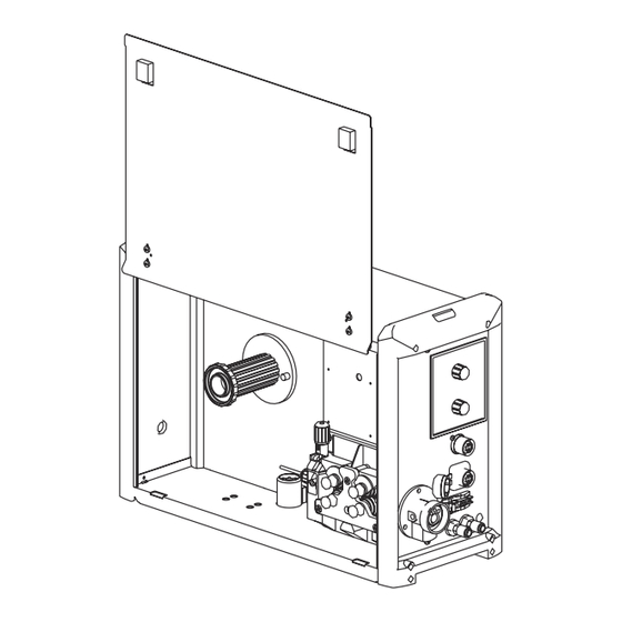
Page 24: Rear Of Wire-Feed Unit
Blanking cover Optional gas economiser valve (12) Blanking cover (10) Current socket for optional installation kit 900 A for VR (11) 7000-11 and VR 7000-30 (13) Bushing for compressed air (12) (14) Bushing for interconnecting (13) hosepack (15) Bushing for external wire... - Page 25 MIG/MAG Standard-Synergic MIG/MAG standard manual welding Job welding TIG welding with touch-down ignition MMA welding IMPORTANT! If the VR 7000 wirefeeder is connected to a TS 4000/5000 power source, MIG/MAG pulse synergic welding is not avail- able. (19) Mode selector switch...
-
Page 26: Wirefeeder Right Side
(24) (23) (23) (22) (22) (21) (21) VR 7000 / VR 7000-11 / VR 7000-30 VR 7000 CMT (21) Shielding gas connection for interconnecting hosepack (22) Water flow connection (blue) for interconnecting hosepack (23) Water return connection (red) for interconnecting hosepack... -
Page 27: Placing Wire-Feed Unit On Power Source
Placing wire-feed unit on power source General The wire-feed units can be placed on the power source if a swivel pin holder is available, e.g.: "PickUp" swivel pin receptor, for use with the "PickUp" trolley "narrow" swivel pin receptor, for use with an upright console "wide"... -
Page 28: Connecting Wire-Feed Unit To Power Source
The wirefeeder is connected to the power source using the interconnecting hosepack. For the "CMT" welding process, a special CMT interconnecting hosepack with ad- ditional LHSB cable is required for connecting the VR 7000 CMT to the CMT power source. Connecting the... - Page 29 NOTE! When connecting the interconnecting hosepack, check that ▶ all connections are connected properly ▶ all cables, leads and hosepacks are undamaged and correctly insulated.
-
Page 30: Connecting The Welding Torch
VR 7000 CMT ... up to max 500 A NOTE! When using a welding current over 500 A, only operate wirefeeders VR 7000-11 and VR 7000-30 with Fronius welding torches that are adequately dimensioned for the welding torch F++ connection. -
Page 31: Connecting The Mig/Mag Robot Welding Torch, Connecting The Automatic Mig/Mag
Connecting the MIG/MAG robot welding torch, connecting the automatic MIG/MAG weld- ing torch MIG/MAG robot welding torch (e.g.: Robacta MIG/MAG robot welding torch with external Drive) wirefeeding hose (e.g. Robacta Drive ext. DFS) Connecting the Control plug for wire buffer CMT drive unit... -
Page 32: Inserting/Replacing Feed Rollers
Inserting/replacing feed rollers General remarks In order to achieve optimum wire electrode feed, the feed rollers must be suit- able for the diameter and alloy of the wire being welded. IMPORTANT! Only use feed rollers that match the wire electrode. An overview of the feed rollers available and their possible areas of use can be found in the spare parts lists. -
Page 33: Inserting The Wirespool, Inserting The Basket-Type Spool
Inserting the wirespool, inserting the basket-type spool Safety CAUTION! Danger from springiness of spooled wire electrode. This can result in severe injuries. ▶ When inserting the wirespool/basket-type spool, hold the end of the wire electrode firmly to avoid injuries caused by the wire electrode springing back. CAUTION! Danger from falling wirespool/basket-type spool. -
Page 34: Inserting The Basket-Type Spool
Inserting the NOTE! basket-type spool When working with basket-type spools, use only the basket-type spool adapter supplied with the wire-feed unit! USA wire-feed units are supplied without bas- ket-type spool adapters. CAUTION! Danger from falling basket-type spool. This can result in serious injury and damage to property. ▶... -
Page 35: Feeding In The Wire Electrode
Feeding in the wire electrode Feed in the wire CAUTION! electrode Danger from springiness of spooled wire electrode. This can result in severe injuries. ▶ When inserting the wire electrode into the 4 roller drive, hold the end of the wire electrode firmly to avoid injuries caused by the wire springing back. -
Page 36: Set The Contact Pressure
Set the contact NOTE! pressure Set the contact pressure in such a way that the wire electrode is not de- formed but nevertheless ensures proper wirefeeding. Contact pressure stand- Semi-cylindric- Trapeze Plastic ard values al rolls rolls rollers Aluminium 3.5 - 4.5 Steel 3 - 4 CrNi... -
Page 37: Adjust The Brake
Adjust the brake Adjusting the NOTE! brake After releasing the torch trigger the wirespool should stop unreeling. Adjust brake if necessary. STOP STOP Design of the CAUTION! brake Danger from falling wirespool. This can result in serious injury and damage to property. ▶... - Page 38 KLEBER, GLUE, COLLE...
-
Page 39: Fitting Wirefeeding Hose For External Wire Electrode
Fitting wirefeeding hose for external wire elec- trode General The wirefeeding hose option serves to protect the external wire electrode while it is being conveyed to the 4 roller drive of the wirefeeder. The wirefeeding hose is available in two versions: for steel (blue) for aluminium (white) Insulated rout-... -
Page 40: Start-Up
Start-up Safety WARNING! Danger from incorrect operation and work that is not carried out properly. This can result in serious personal injury and damage to property. ▶ All the work and functions described in this document must only be carried out by technically trained and qualified personnel. -
Page 41: Care, Maintenance And Disposal
Care, maintenance and disposal General remarks Under normal operating conditions, the wire-feed unit requires only a minimum of care and maintenance. However, some important points must be noted to en- sure that the welding system remains in a usable condition for many years. WARNING! Danger from electrical current. -
Page 42: Technical Data
Technical data VR 7000 Supply voltage 55 V DC (supply from the power source) Nominal current Wire speed 0.5 - 22 m/min 19.69 - 866.14 ipm Degree of protection IP 23 Dimensions l x w x h 640 x 260 x 430 mm 25.20 x 10.24 x 16.93 in. - Page 43 Original Fronius Maximum coolant pressure 6 bar 87 psi LocalNet data rate 57600 baud LHSB connection VR 7000-30 Supply voltage 55 V DC (supply from the power source) Nominal current Wire speed 0.5 - 30 m/min 19.69 - 1181.10 ipm...
-
Page 44: Vr 7000 Cmt
VR 7000 CMT Supply voltage 55 V DC (supply from the power source) Nominal current Wire speed 0.5 - 22 m/min 19.69 - 866.14 ipm Degree of protection IP 23 Dimensions l x w x h 640 x 260 x 430 mm 25.20 x 10.24 x 16.93 in.
Need help?
Do you have a question about the VR 7000 and is the answer not in the manual?
Questions and answers