Table of Contents
Advertisement
Quick Links
Advertisement
Table of Contents
Troubleshooting

Related Manuals for Fronius Virtual Welding 2.0 MobileCase


Summary of Contents for Fronius Virtual Welding 2.0 MobileCase
- Page 1 Perfect Welding / Perfect Charging / / Solar Energy Operating Instructions Virtual Welding 2.0 Virtual welding system 42,0426,0089,EN 011-13052020 Fronius prints on elemental chlorine free paper (ECF) sourced from certified sustainable forests (FSC).
-
Page 3: Table Of Contents
Contents Safety rules ..............................Explanation of safety notices ........................ General ..............................Environmental conditions........................Obligations of the operator........................Obligations of personnel ........................Mains connection ..........................Dangers from mains current ......................... EMC device classifications ........................Specific hazards............................ Safety measures at the installation location and during transport ............Safety measures in normal operation .................... - Page 4 Start-up Training concept and commissioning sequence ..................Training concept ........................... Commissioning sequence........................First step of commissioning: creating a curriculum ..................General ..............................Configuring a USB flash drive....................... Creating a knowledge check (test)......................Saving content to the USB flash drive ....................Importing content ..........................
- Page 5 Changing the robot manufacturer ......................Description ............................Quiz................................Function ..............................Enabling/disabling or importing/exporting quizzes................Exporting a quiz ............................ Creating a quiz............................100 Importing a quiz ............................ 102 Setup menu Permissions and opening the Setup menu ....................107 Different permissions ..........................107 Access the Setup menu ........................
-
Page 7: Safety Rules
Safety rules Explanation of DANGER! safety notices Indicates immediate danger. ► If not avoided, death or serious injury will result. WARNING! Indicates a potentially hazardous situation. ► If not avoided, death or serious injury may result. CAUTION! Indicates a situation where damage or injury could occur. ►... -
Page 8: Obligations Of The Operator
The device must only be installed and operated inside dry and enclosed premises. Ambient temperature range: during operation: - 10 °C to + 35 °C (14 °F to 95 °F) during transport and storage: - 25 °C to + 55 °C (-13 °F to 131 °F) Relative humidity: up to 50 % at 35 °C (95 °F) up to 90 % at 20 °C (68 °F) -
Page 9: Emc Device Classifications
All cables and leads must be secured, undamaged, insulated and adequately dimen- sioned. Loose connectors, scorched, damaged or inadequately dimensioned cables and leads must be replaced immediately. Do not wrap cables or leads around the body or parts of the body. Arrange for the mains cable to be checked regularly by a qualified electrician to ensure the ground conductor is functioning properly. -
Page 10: Specific Hazards
Check for possible problems, and check and evaluate neighbouring devices' resistance to interference according to national and international requirements. For example: Safety devices Network, signal and data transfer lines IT and telecommunications devices Measuring and calibrating devices Supporting measures for avoidance of EMC problems: Mains supply Use only with the power cable supplied If electromagnetic interference arises despite the correct mains connection, addi-... -
Page 11: Safety Measures In Normal Operation
(e.g. relevant product standards of the EN 60 974 se- ries). Fronius International GmbH hereby declares that the device is compliant with Directive 2014/53/EU. The full text on the EU Declaration of Conformity can be found at the following address: http://www.fronius.com... -
Page 12: Copyright
Copyright Copyright of these operating instructions remains with the manufacturer. The text and illustrations are all technically correct at the time of printing. We reserve the right to make changes. The contents of the operating instructions shall not provide the ba- sis for any claims whatsoever on the part of the purchaser. -
Page 13: General Information
General information... -
Page 15: General
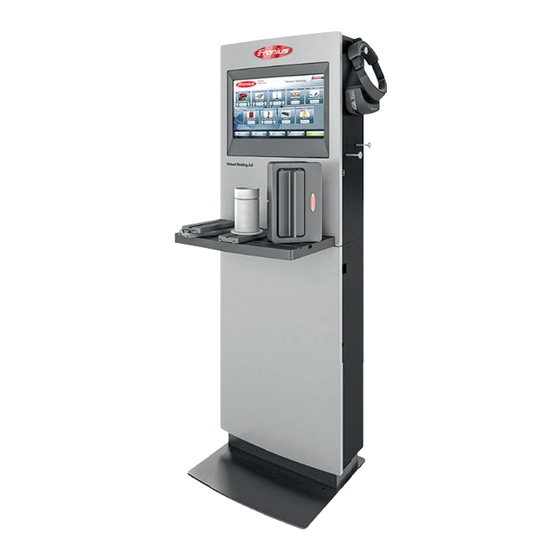
General Device concept Virtual Welding is used to teach welding in a realistic environment. The following bene- fits are provided by Virtual Welding: Very low cost of training No consuma- bles are required (wire electrodes, wel- ding gas, etc.) The trainees are not exposed to the hazards of welding (heat, welding fu- mes, welding spatter, noise, etc.) The learning progress of the trainees is... -
Page 16: Warning Notices On The Device
The device is intended for welding simulation only with the software and hardware supplied by the manufacturer. Any use above and beyond this purpose is deemed improper. The manufacturer shall not be held liable for any damage arising from such usage. Intended use also means: Fully reading and understanding all the instructions given in the Operating Instructions Fully reading and understanding all warning notices on the device... -
Page 17: Software And Product Updates
Incorrect operation or poorly executed work can cause serious injury or damage. The de- vice may only be installed, repaired and maintained by trained and qualified personnel. The following documents must be completely read and understood: These Operating Instructions All the Operating Instructions for the system components, especially the safety rules Do not dispose of used devices with domestic waste. -
Page 18: Scope Of Delivery And Optional Function Packages
Scope of delivery and optional function packages Scope of supply In addition to the StandUp Terminal or MobileCase, the following system components are supplied: Work table Workpiece holder Single-V butt weld layer 1 (square butt weld) workpie- Fillet weld workpiece Single-V butt weld layer 2 and 3 (square butt weld) workpiece... -
Page 19: Function Packages
Pipe workpiece 2 NFC keys Supplied with the StandUp Terminal, but not shown: 3D glasses 4 keys 4 screws M8x80 mm with washers, for screwing together the upper and lower parts Mounting bracket including 4 screws M8x16 mm and washers This document Mains cable (for connecting to a power socket) Cable for 3D glasses... - Page 20 Rod electrode function package...
-
Page 21: Controls, Connections And Mechanical Components
Controls, connections and mechani- cal components... -
Page 23: Touchscreen And Sensor
Touchscreen and sensor Touchscreen and sensor Touchscreen and sensor on the StandUp Terminal Sensor on MobileCase The touchscreen (1) allows intuitive operation by means of virtual buttons. The sensor (2), in conjunction with the supplied NFC keys, performs the following func- tions: Touch sensor with the NFC key once = Open terminal management in order to create curricula, for example - see section... -
Page 24: Control Elements And Connections
Control elements and connections Connection sock- Connection for the workpiece ets on the Stan- holder dUp Terminal for connecting the sensor cable of the workpiece holder Connection for robotics clip or filler material for connecting the sensor cable of the robotics clip; for connecting the sensor cable of the filler material (TIG) Connection 1 for welding torch... -
Page 25: Controls And Connection Sockets On The Mobilecase
LAN connection socket for connecting a LAN network cable 3D glasses connection socket for connecting the data cable of the (5) (6) (7) (8) 3D glasses USB port for connecting the power cable of the 3D glasses Connection for external display provided for connecting an external monitor or projector... - Page 26 LAN connection socket for connecting a LAN network cable Connection 1 for welding torch for connecting the control cable of the welding torch; for connecting the control cable of the electrode holder Connection 2 for welding torch for connecting the sensor cable of the welding torch; for connecting the sensor cable of the electrode holder Connection for robotics clip or filler material for connecting the sensor cable of the robotics clip;...
-
Page 27: Location Of The Ventilation Openings
Location of the ventilation openings Ventilation open- Ventilation openings at the front ings on the Stan- of the device dUp Terminal Ventilation openings at the rear of the device Ventilation open- Ventilation openings at the front ings on the Mobil- of the device eCase... - Page 28 Ventilation openings at the rear of the device...
-
Page 29: Installation
Installation... -
Page 31: Before Installation And Commissioning
Before installation and commissioning Safety WARNING! Danger due to incorrect operation and incorrectly performed work. This can result in serious injury and damage to property. ► All the work and functions described in this document must only be carried out by trained and qualified personnel in accordance with the applicable national and interna- tional standards. - Page 32 Ensure that the permissible environmental conditions are maintained at all times. For more details on environmental conditions, see section Environmental conditions on page 7. Special provisions apply in areas at risk of fire or explosion - observe relevant national and international regulations.
-
Page 33: Installing The Standup Terminal
Installing the StandUp Terminal Safety WARNING! Danger from electric current. This can result in serious injury or death. ► Before beginning work, switch off the device and disconnect from the mains supply. ► Secure the device against it being switched back on again. WARNING! Danger due to improper installation. - Page 34 Top of StandUp Terminal, side view (2) = Mounting bracket (3) = Screws with washers...
-
Page 35: Assembling The Standup Terminal And Tightening The Screws
Assembling the Place the bottom part in its final instal- StandUp Terminal lation position (3) (3) (3) (3) and tightening Make sure that the mounting bra- the screws ckets (2) extend to the wall Place the upper part on the lower part Screw the two parts together using the four socket screws (1) M8x80 mm sup- plied... - Page 36 Tool table, standard mounting: Slide the tool table (8) fully into the opening (9) Tool table, overhead mounting: NOTE! To aid clarity, the mounting brackets for wall mounting have been removed in the following images. However, the StandUp Terminal must always be screwed to the wall with the mounting brackets.
- Page 37 (11) (10) Top of StandUp Terminal Lock the tool table in the holders (10) and (11) as shown below (12) (10) (11) Top of StandUp Terminal with tool table fitted (10) = Holder (11) = Holder (12) = Tool table CAUTION! Danger from falling tool table.
-
Page 38: Waiting Time Until The Power Connection Is Established
Waiting time until CAUTION! the power con- nection is estab- Risk of poor acclimatisation of components by connecting the device to the mains lished too early. This can result in damage to the device ► Do not connect the device to the mains and switch it on until at least four hours after the installation has been completed. -
Page 39: Installing The Mobilecase
Installing the MobileCase Safety WARNING! Danger from electric current. This can result in serious injury or death. ► Before beginning work, switch off the device and disconnect from the mains supply. ► Secure the device against it being switched back on again. WARNING! Danger due to improper installation. -
Page 40: Waiting Time Until The Power Connection Is Established
Slide the tool table (2) fully into the opening (1) Refer to the Installation Instructions of the relevant installation kit for the overhead mounting of the tool table CAUTION! Risk of poor acclimatisation of components by connecting the device to the mains too early. -
Page 41: Fitting And Connecting The System Components
Fitting and connecting the system components Fitting and con- necting the tool and other system components NOTE! The workpiece holder (1) is shown in the standard mounting position. The workpie- ce holder (1) can be fitted in other positions on the tool table. These are displayed at the end of this section. - Page 42 Insert the desired workpiece into the workpiece holder as shown above Connect the 3D glasses to the Virtual Welding system Connect the welding torch/electrode holder to the Virtual Welding system For more information on the connection sockets on the StandUp Terminal, see section Connection sockets on the StandUp Termi- from page on the MobileCase, see section...
- Page 43 Alternative mounting positions of workpiece holder 1: Insert the overhang (3) into the slot (4) on the tool table Alternative mounting positions of workpiece holder 2: Insert the overhang (5) into the slot (4) on the tool table CAUTION! Danger from falling workpiece holder. This can result in injury and damage to property.
-
Page 44: Switching On, Getting Started
Switching on, getting started Connecting the WARNING! mains cable and switching on the Danger from electric current. device This can result in serious injury or death. ► Use only the supplied mains cable to connect to the mains. ► Only plug the mains cable into a correctly earthed socket. CAUTION! Risk of poor acclimatisation of components by connecting the device to the mains too early. -
Page 45: Start-Up
Start-up... -
Page 47: Training Concept And Commissioning Sequence
Commissioning Create a curriculum and chapters sequence – This step is only necessary if no Fronius licences have been purchased with the Virtual Welding system – If Fronius licences have been purchased with the system, several curricula are pre-installed on the system... -
Page 48: First Step Of Commissioning: Creating A Curriculum
First step of commissioning: creating a curriculum General A curriculum needs to be created only if no Fronius licences have been purchased with the Virtual Welding system. If you purchased Fronius licences with the system, this section can be skipped and you can start with creating courses. -
Page 49: Creating A Knowledge Check (Test)
Select button (3) to configure the USB flash drive Creating a knowl- The knowledge check is part of the course mode and is used to check whether the edge check (test) learned theory content has been understood. It is recommended to include in the knowledge check only questions that can be an- swered through the theoretical content provided. -
Page 50: Saving Content To The Usb Flash Drive
Select button (8) and save the knowledge check in the "knowledgecheck" folder on the USB flash drive Saving is only possible once all the fields in theQuizEditor have been completed If desired, a quiz can also be created. For details, see section Quiz from page 99. -
Page 51: Importing Content
Copy all desired learning content to the "theory" folder Use PDF only Copy customer-specific WPS to the "wps" folder WPS from Fronius are already installed on the system The knowledge check created in the previous step is already in the "knowledgecheck" folder the "quiz"... - Page 52 Import theory content: Select the desired file, for example (4) Select button (5) Import theory content: Make sure the correct welding process is selected (6) Select checkbox (7) to use the original file name Select button (8) to import the file...
- Page 53 (10) (11) Import a knowledge check: Select button (9) Select tab (10) Select button (11) (12) (13) Import a knowledge check: Select the desired file, for example (12) Select button (13)
- Page 54 (15) (14) (16) Import a knowledge check: Make sure that the correct welding process is selected (14) Select checkbox (15) to use the original file name Select button (16) to import the file (18) (19) (17) Import a WPS: Select button (17) Select tab (18) Select button (19)
-
Page 55: Merging Content Into A Curriculum
(20) (21) Import a WPS: Select the desired file, for example (20) Select button (21) (23) (22) (24) Import a WPS: Make sure that the correct welding process is selected (22) Select checkbox (23) to use the original file name Select button (24) to import the file Plug the USB flash drive into the system The USB flash drive can be used to store curricula (backup copy), for example... - Page 56 The curriculum can be divided into individual chapters as desired It is recommended that each chapter builds on previously learned knowledge. For example, a chapter with easy welding tasks and related content, a chapter with medium welding tasks and related contents, and so forth. Individual courses for users can be created from the curriculum.
- Page 57 Select which content types are to be inserted into the chapter (4) Depending on your needs, you can select individual content types or all content types Select button (5) In the next steps, the individual contents are inserted into the chapter Add training content to the first chapter: (Only possible if this content type was selected when the chapter was created) (11)
- Page 58 (13) (13) (12) (14) Enable/disable the required tasks using the buttons (12) If a task is enabled, it can be disabled again when the course is created If a task is disabled, it will not be possible to later enable the task in this curriculum Use the arrow keys (13) to select the extent of the permissible deviation (Ghost) (for more details on the Ghost see section Ghost...
- Page 59 (17) (16) Make sure the correct welding process is selected If necessary, select button (16) to change the welding process Select button (17) to insert the desired WPS into the chapter Add theory content to the first chapter: (Only possible if this content type was selected when creating the chapter) Make sure the correct welding process is selected If necessary, select button (6) to change the welding process Select button (7) to insert the desired theory content into the chapter...
- Page 60 Make sure the correct welding process is selected If necessary, select button (6) to change the welding process Select button (7) to insert the desired knowledge check into the chapter Each chapter can contain only one knowledge check (10) Select the percentage of questions that need to be answered correctly in order for the knowledge check to be passed (8) A value of 80% or more is recommended The settings can be adjusted again when the course is created...
- Page 61 (18) Give this chapter a name Select button (18) Complete the curriculum: (20) (19) Select button (19) to complete and create the curriculum If you wish, a new chapter can also be added to the curriculum at this point. In this case, select the button (20) and repeat the previous steps...
- Page 62 (21) Give the curriculum a name Select button (21) (22) The new curriculum is displayed in the overview (22)
-
Page 63: Second Step Of Commissioning: Creating A Course
Second step of commissioning: creating a course Uses of a course Individual courses can be compiled for the desired group of trainees from the curricu- If there are multiple Virtual Welding systems in a network, the courses can be as- signed to different Virtual Welding systems, such as: Course A is assigned to the systems used for basic training Course B is assigned to the systems used for advanced training... - Page 64 Make sure the correct welding process is selected If necessary, select button (6) to change the welding process Select a curriculum to use as the basis for the course. For example (9) Fronius curricula are displayed on tab (7) Self-created curricula are displayed on tab (8) (10)
- Page 65 (13) Give the course a name Select button (13) The new course is now shown in the course overview After creating all the courses you want, it is recommended that you back up your data. For more details on this, see section Creating a backup (exporting data) from page 112.
-
Page 66: Third Step Of Commissioning: Assigning Courses
Third step of commissioning: assigning courses Assigning cours- Touch the NFC key on the Virtual Welding system sensor to open terminal manage- es to the Virtual ment Welding system Touchscreen and sensor For the sensor location, see section on page Select button (1) Available terminals are displayed (2) If there is only one terminal on the network, the serial number is displayed as the... -
Page 67: Assigning Courses To Multiple Terminals
Select button (6) The course has been assigned to the terminal Assigning cours- If multiple Virtual Welding systems are being used, it is possible to combine them into es to multiple ter- groups (cluster networking) minals See section Creating a cluster network from page for a description of how to create groups... -
Page 68: Fourth Step Of Commissioning: Activating Course Mode, Preparing The System For Users
Fourth step of commissioning: activating course mode, preparing the system for users Activating course Touch the NFC key on the Virtual Welding system sensor to open terminal manage- mode ment For the sensor location, see section Touchscreen and sensor on page Select button (1) Select tab (2) Select button (3) to activate course mode... -
Page 69: Ghost
Ghost... -
Page 71: Explanation And Configuration Options
Explanation and configuration options Explanation The Ghost is a virtual welding torch that is displayed during the welding tasks The Ghost shows the ideal movement when welding A Ghost is saved for all welding tasks as standard (default Ghost) The New Ghost button (1) allows you to create what is known as a variable Ghost A variableGhost can be created in addition to the default Ghost and adapted to your own requirements A variable Ghost can be created for all welding processes... - Page 72 Use the arrow keys to make the desired settings Select button (4) Select button (5)
- Page 73 Enter a name for the variable Ghost Select button (6) Follow the instructions on the touchscreen NOTE! With Virtual Welding Robotics, a distinction is made between Polygon and Cycles when creating a Ghost: ► Polygon: Enables a completely free path to be traced (inscription, etc.) ►...
-
Page 75: Available Modes On The Virtual Welding System
Available modes on the Virtual Weld- ing system... -
Page 77: Course Mode
Course mode Explanation In course mode, courses with varying degrees of difficulty can easily be configured or adapted to individual requirements. The courses and the curricula on which they are based are easy to access. The results can be compared with the help of ranking lists, so that it is possible to address the precise needs of the trainee welder. -
Page 78: Profile
Profile To use the course mode properly, a profile must be created for each user. It is therefore recommended to create a profile for each user. A profile allows you to: Save data for each user (trainee) Follow-up on the latest welding results of each user Get an overview of each user via the latest ranking lists Create a profile: Select button (1) - Page 79 Select button (3) Enter required data Read and understand the text next to the checkbox (4) and select the checkbox (4) Select button (5) Confirm the message displayed...
-
Page 80: Description Of Rankings Lists, Exporting Course Data
Once the settings have been completed, the profile of the respective user can be opened using button (6) Description of Each course has its own ranking list rankings lists, ex- The ranking lists allow a user's welding results to compared with the welding results porting course of the other participants (allVirtual Welding systems in the network and their users are data... - Page 81 Select button (1) Select tab (2) Make sure the correct welding process is selected If necessary, select button (3) to change the welding process Select button (4) next to the desired course Select button (5) The course data is stored on the USB flash drive...
-
Page 82: Open Mode
Open mode Explanation Open mode is used to demonstrate the Virtual Welding system All the available welding parameters and exercises can be selected without any train- ing plan Scores will not be saved In open mode, the following functions are available: Free training (practical welding tasks) Quiz Quiz - for more details, see section... -
Page 83: Showroom Mode
Showroom mode Explanation Showroom mode has the fewest features of any mode, making it ideal for user-free operation, such as in entrance halls Only open training can be selected in showroom mode Enabling show- Touch the NFC key on the Virtual Welding system sensor to open terminal manage- room mode ment For the sensor location, see section... -
Page 85: Calibration
Calibration... -
Page 87: System Calibration
System calibration Function The system calibration is the calibration of the magnetic sensors in the individual sys- tem components (workpiece, welding torch, etc.) The system calibration compares the positions of the individual components to each other The system calibration must always be carried out when starting for the first time and when the Virtual Welding system is moved to a different location Performing sys- Touch the NFC key on the Virtual Welding system sensor to open terminal manage-... - Page 88 Select the welding process whose system components are to be calibrated Follow the instructions on the touchscreen...
-
Page 89: Room Calibration
Room calibration Function Room calibration calibrates the cameras in the 3D glasses (optical calibration) The room calibration ensures that the 3D glasses function properly The room calibration must always be carried out when starting for the first time and when the Virtual Welding system is moved to a different location Performing room NOTE! calibration... - Page 90 Select button (2) Select tab (3) Select button (4) Follow the instructions on the touchscreen / in the glasses...
-
Page 91: Component Calibration
Component calibration Function The component calibration compares the data of the system calibration (= calibration of magnetic sensors) and the room calibration (= calibration of the cameras of the 3D glasses) Component calibration is started automatically before each training session Performing com- Touch the NFC key on the Virtual Welding system sensor to open terminal manage- ponent calibra-... - Page 92 Follow the instructions on the touchscreen...
-
Page 93: Changing The Camera Settings
Changing the camera settings Function The camera setting is used to adjust the zoom factor Depending on your preferences, this setting can be used to move the displayed image closer or farther away Changing the Touch the NFC key on the Virtual Welding system sensor to open terminal manage- camera settings ment For the sensor location, see section... - Page 94 Follow the on-screen instructions...
-
Page 95: Additional Settings
Additional settings... -
Page 97: Licence Management
Licence management Function System-relevant information, such as the following, are shown in the Licensemanager ar- Hardware dongle serial number Installed licences etc. Additional Virtual Welding licences, such as licences to enable additional welding process- es, can also be installed here. Opening licence Touch the NFC key on the Virtual Welding system sensor to open terminal manage- management (Li-... -
Page 98: Changing The Robot Manufacturer
Changing the robot manufacturer Description The robot manufacturer can be set with a corresponding licence. This shows the arm of the respective robot manufacturer during robotic welding. Touch the NFC key on the Virtual Welding system sensor to open terminal manage- ment For the sensor location, see section Touchscreen and sensor... -
Page 99: Quiz
Quiz Function The quiz is a playful knowledge check, the results are not saved The quiz is only available in open mode For more details on open mode, see section on page The system is supplied with a 70-question quiz as standard Enabling/disa- Touch the NFC key on the Virtual Welding system sensor to open terminal manage- bling or import-... -
Page 100: Creating A Quiz
Select button (1) Select tab (2) Select button (3) Select tab (4) Select button (5) to export the pre-installed quiz Select button (6) to export individual/own segments Creating a quiz Connect a USB flash drive configured for Virtual Welding to a PC Configuring For instructions on how to configure a USB flash drive, see section a USB flash drive... - Page 101 Select button (1) Fill in text boxes (2) - (5) for the first quiz question Select button (6) to add another question Repeat these two steps as many times as you like NOTE! It is recommended that the quiz be given a practical and unique file name when sav- ing, since this file name can be transferred to the Virtual Welding system when later imported (this means that you do not have to re-enter the name of the quiz on the Virtual Welding system).
-
Page 102: Importing A Quiz
Select button (7) and save the quiz in the "quiz" folder on the USB flash drive Saving is only possible once all the fields in the QuizEditor have been completed Importing a quiz Connect the USB flash drive with the quiz data to the USB port of the Virtual Welding system Touch the NFC key on the Virtual Welding system sensor to open terminal manage- ment... - Page 103 Select button (3) Select tab (4) Select button (5) Select and import the desired data...
-
Page 105: Setup Menu
Setup menu... -
Page 107: Permissions And Opening The Setup Menu
Permissions and opening the Setup menu Different permis- Depending on whether the NFC key belongs to an administrator or a user, this opens either sions the full Setup menu for administrators or a simplified Setup menu for users. The restricted range of settings that is available to users is described separately below. For more details on teaching and removing NFC keys, see section Performing sensor re- gistration (only available to administrators) -
Page 108: Network Menu Item
Network menu item Description The cluster network function allows you to create a local network within several Virtual Welding systems. This makes it possible to control the entire course management of the Virtual Welding systems from one master device. Master Slave Slave Router... - Page 109 MobileCase 1 (Master) Select checkbox (2) Select checkbox (3) Select button (4) and assign a name Note down the master mac ID The MAC ID must be entered for all other systems (slave) Select button (5) and assign a password Select button (7) to save the entries The current system is now defined as the master Define all other systems as slaves (the settings must be made individually on each...
- Page 110 Define all other systems as a slave in the same way NOTE! If the master is restarted during active cluster networking, all the slaves will also have to be restarted in order to re-establish a connection with the master.
-
Page 111: Other Settings Menu Item
Other settings menu item Viewing the li- The licence list contains the licences currently available on the Virtual Welding system, in- cence list cluding additional information (such as licence name, description, etc.). Open the Setup menu - see Access the Setup menu on page Select button (1) The licence list is displayed... -
Page 112: Creating A Backup (Exporting Data)
Creating a back- The export function can be used to store Virtual Welding system data on a USB flash up (exporting da- drive, such as to back up data. It is recommended to back up the Virtual Welding system data once a week. Export data: Connect a USB flash drive to the USB port of the Virtual Welding system Access the Setup menu... -
Page 113: Management Code
Select button (2) to export all data. This includes: Courses Curricula Profiles Ranking lists (without playback function) Settings for the variable Ghost Select button (3) to export only the variable Ghost settings The button can only be selected if a variable Ghost has been created Select button (4) to start the data export Disconnect the USB flash drive from the Virtual Welding Management... -
Page 114: Language Settings
Open the Setup menu - see Access the Setup menu on page Select button (1) Enter the desired management code Select button (2) Language set- The Virtual Welding system has up to eight languages tings Of these eight languages, a maximum of six languages can be enabled The language settings determine which languages are enabled and can therefore be selected by the user One of the active languages must be defined as the default language... - Page 115 Open the Setup menu - see Access the Setup menu on page Select button (1) Change the language settings: In area (2), select the languages to be enabled Select button (4) to save Define the default language: In area (3), define the default language (standard) Select button (4) to save...
-
Page 116: Importing Data (Only Available To Administrators)
Importing data Selected settings for the Virtual Welding system can be imported from a USB flash drive. (only available to administrators) Risk of data loss: When you import data, the settings saved on the terminal are overwritten. Import data: Connect a USB flash drive to the USB port of the Virtual Welding system Open the Setup menu - see Access the Setup menu on page... -
Page 117: Viewing/Changing Country Profiles (Only Available To Administrators)
Select button (2) to import all data. This includes: Courses Curricula Profiles Ranking lists (without playback function) Settings for the variable Ghost Select button (3) to import only the variable Ghost settings Button (3) can only be selected if the corresponding data is available Select the content to import, for example (4) and (5) Select button (6) to start the data import Viewing/chang-... -
Page 118: Restoring Factory Settings (Only Available To Administrators)
Open the Setup menu - see Access the Setup menu on page Select button (1) Select the desired country profile, for example (2) Select button (3) to save Restoring factory NOTE! settings (only available to ad- Risk of data loss. ministrators) When you reset the system to the factory settings, all settings in the Setup menu are reset to their factory defaults. -
Page 119: Performing Sensor Registration (Only Available To Administrators)
Open the Setup menu - see Access the Setup menu on page Select button (1) Press button (2) to restore factory settings Performing sen- Two NFC keys are supplied with each Virtual Welding system. They are used to ac- sor registration cess terminal management or the Setup menu (only available to When the system is started for the first time, the NFC key can be used to create an... - Page 120 Open the Setup menu - see Access the Setup menu on page Select button (1) Teach in NFC key for administrators: Keep the NFC key in question ready In area (2), select the button for the administrator When the relevant prompt appears on the touchscreen, hold the NFC key above the sensor Confirm the following message Teach in NFC key for users:...
- Page 121 When the relevant prompt appears on the touchscreen, hold the NFC key above the sensor Confirm the following message Remove NFC key for administrators: Keep the NFC key in question ready In area (3), select the button for the administrator When the relevant prompt appears on the touchscreen, hold the NFC key above the sensor Confirm the following message...
-
Page 122: Technical Settings Menu Item
Technical settings menu item Setting the time and date (only available to ad- ministrators) Access the Setup menu Open the Setup menu - see on page Select button (1) Change the desired data Showing the NSB The NSB number is the version number of the Virtual Welding software. This number is number required for support questions, for example. -
Page 123: Test Screen (Only Available To Administrators)
Test screen (only The test screen allows you to check the screen settings. available to ad- ministrators) Open the Setup menu - see Access the Setup menu on page Select button (1) Touch any area of the touchscreen display Every touch of the touchscreen display causes the next test screen to appear When the process is complete, select button (2) -
Page 124: Setting The Model
Setting the model Open the Setup menu - see Access the Setup menu on page Select button (1) Select the correct data Save entries Enabling Scan- The menu item ScanDisk is used to identify and correct errors on the hard disk. This will Disk (only availa- usually make the system run more efficiently. -
Page 125: Performing Touchscreen Test (Only Available To Administrators)
Select checkbox (2) Select button (3) ScanDisk will run the next time the Virtual Welding system is restarted NOTE! As long as ScanDisk is enabled, it is performed each time the Virtual Welding Sys- tem is started. Performing The touchscreen test is used to check the touchscreen calibration. touchscreen test (only available to administrators) -
Page 126: Adjusting The Volume (Only Available To Administrators)
Touch any area of the touchscreen display A square shows where the touch was registered When the test is complete, select button (2) Adjusting the vol- ume (only availa- ble to administrators) Open the Setup menu - see Access the Setup menu on page Select button (1) - Page 127 Make the desired settings Select button (2)
-
Page 129: Troubleshooting, Maintenance And Disposal
Troubleshooting, maintenance and disposal... -
Page 131: Troubleshooting
Troubleshooting General Contact our After-Sales Service team with a detailed description of the error, if Errors occur that are not listed below The troubleshooting measures listed are unsuccessful Safety WARNING! Danger due to incorrect operation and incorrectly performed work. This can result in serious injury and damage to property. ►... - Page 132 Welding torch / electrode holder positioning is different from that shown in the 3D glasses Cause: Incorrect calibration of individual components Remedy: First step: Press the Fronius logo for 3 seconds - this starts component cali- bration. For more details on component calibration, see section Component calibration from page...
- Page 133 Cause: Faulty component calibration Remedy: Press the Fronius logo for 3 seconds - this starts component calibration. For more details on component calibration, see section Component calibration from page The 3D glasses are not working...
-
Page 134: Maintenance And Disposal
Maintenance and disposal General Under normal operating conditions, the device requires only a minimum of care and main- tenance. However, it is essential to observe certain points to ensure that the device gives reliable service for many years. Safety WARNING! Danger due to incorrect operation and incorrectly performed work. -
Page 135: Update
Update... -
Page 137: Updating The Software
Updating the software Preparing for the Prepare the Virtual Welding system for the update: update Disconnect 3D glasses Back up data - see section Creating a backup (exporting data) from page Connect a keyboard to the Virtual Welding system Configure the USB flash drive for the update: Download the update folder to a PC The update folder can be found at www.virtualwelding.com Unzip the update folder... - Page 138 VWUPDATE Use button (3) to select the ".iso" file that is located in the update folder...
- Page 139 VWUPDATE Use button (4) to select "GPT"...
- Page 140 VWUPDATE Use button (5) to select "EUFI" or "BIOS" Depending on the system, one of the two options is available...
- Page 141 VWUPDATE Enter "VWUPDATE" in field (6)
- Page 142 VWUPDATE Select "Large FAT32 (Default)" using button (7); select "32 kilobytes (Default)" with button (8)
- Page 143 VWUPDATE (10) Select checkbox (9) and (10)
- Page 144 VWUPDATE (11) Select button (11)
- Page 145 (12) By selecting button (12), all existing data on the USB flash drive is deleted and all data re- quired for the update is saved on the USB flash drive. Select button (12)
-
Page 146: Updating The Software
(13) Once the load bar (13) is completely green, the USB flash drive is configured and can be used to update the Virtual Welding system Updating the soft- Turn the mains switch of the Virtual Welding system to the "O" position ware Connect the USB flash drive to the USB port of the Virtual Welding system Turn the mains switch of the Virtual Welding system to the "I"... - Page 147 BIOS menu Use the arrow keys on the keyboard to select the "Save & Exit" menu item (1)
- Page 148 Select the USB flash drive containing the update data (2) under the "Boot Override" menu item The USB flash drive is always called "Flash Drive" or "Flash Disk" If the USB flash drive is not displayed, the USB flash drive has not been detected. In this case: Turn the mains switch of the Virtual Welding system to the "O"...
-
Page 149: Technical Data
Technical data... -
Page 151: Technical Data
Technical data Special voltages For devices designed for special voltages, the technical data on the rating plate applies. StandUp Termi- Mains voltage +/- 10% 110 V - 230 V nal, MobileCase Grid frequency 50/60 Hz Mains fuse protection 2 x 3.15 A slow-blow Current consumption max. - Page 152 FRONIUS INTERNATIONAL GMBH Froniusstraße 1 A-4643 Pettenbach AUSTRIA contact@fronius.com www.fronius.com Under www.fronius.com/contact you will find the addresses of all Fronius Sales & Service Partners and locations.
Need help?
Do you have a question about the Virtual Welding 2.0 MobileCase and is the answer not in the manual?
Questions and answers