Table of Contents
Troubleshooting

Subscribe to Our Youtube Channel
Related Manuals for Fronius Virtual Welding


Summary of Contents for Fronius Virtual Welding
- Page 1 / Perfect Charging / Perfect Welding / Solar Energy Operating Instructions Virtual Welding Training 42,0426,0089,EN 001-04112019 Fronius prints on elemental chlorine free paper (ECF) sourced from certified sustainable forests (FSC).
- Page 3 Thank you for the trust you have placed in our company and congratulations on buying this high-quality Fronius product. These instructions will help you familiarise yourself with the product. Reading the instructions carefully will enable you to learn about the many different features it has to offer.
-
Page 5: Table Of Contents
Contents Safety rules ..............................General ..............................Proper use ............................Environmental conditions........................Obligations of the operator........................Obligations of personnel ........................Mains connection ..........................Dangers from mains current ......................... EMC device classifications ........................Specific hazards............................ Safety measures at the installation location and during transport ............Safety measures in normal operation .................... - Page 6 Access ..............................Overview ............................... Curriculum..............................Curricula..............................Creating a new curriculum ........................MIG/MAG tasks............................. Rod electrode tasks ..........................TIG tasks............................... Robotics tasks............................For all training courses.......................... Courses..............................Courses..............................Creating a new course .......................... Ghost ................................. Ghost ..............................Creating a Ghost........................... Ghost: Defining the record grid and welding speed ................Ghost: Executing reference welding .....................
- Page 7 Disposal ..............................147 Update ............................... 148 Installing/updating the software ......................148 Appendix Technical data............................153 Special voltages............................ 153 Virtual Welding terminal and MobileCase ..................... 153 Standards.............................. 153 Spare parts list: Virtual Welding ......................... 154 Glossary..............................162 ADSL..............................162 APN............................... 162 AT commands............................
- Page 8 LAN ............................... 163 PIN ................................ 163 Point-to-Point Protocol .......................... 163 PPPoE ..............................163 PPTP..............................163 Protocol..............................163 RAM ..............................164 S0 bus for ISDN ............................ 164 Server ..............................164 SIM card..............................164 Splitter..............................164 Subnet mask ............................164 TCP/IP ..............................164 UMTS..............................
-
Page 9: Safety Rules
Safety rules General The device is manufactured using state-of-the-art technology and according to recognised safety standards. If used incorrectly or misused, however, it can cause: injury or death to the operator or a third party, damage to the device and other material assets belonging to the operat- ing company, inefficient operation of the device. -
Page 10: Proper Use
Proper use The device is to be used exclusively for its intended purpose. The device is intended exclusively for the simulation of manual MIG/MAG welding and manual metal arc welding using the hardware and software pro- vided by the manufacturer. Any use above and beyond this purpose is deemed improper. -
Page 11: Obligations Of The Operator
Mains connection The mains voltage and frequency must conform to the data on the rating plate. The Virtual Welding system must be connected to a properly installed, fused and earthed mains socket. If the device has been supplied without the cable normally employed in your country, bring the mains plug and cable into line with national standards. -
Page 12: Dangers From Mains Current
Dangers from An electric shock is potentially life threatening and can be fatal. mains current Do not touch live parts either inside or outside the device. All cables and leads must be secured, undamaged, insulated and adequately dimensioned. Loose connections, scorched, damaged or inadequately dimen- sioned cables and leads must be repaired/replaced immediately. -
Page 13: Emc Device Classifications
EMC device clas- Virtual Welding is an emission class A device: sifications It is only designed for use in an industrial setting It can cause conducted and emitted interference in other areas. In certain cases, even though a device complies with the standard limit values for emissions, it may affect the application area for which it was designed (e.g. -
Page 14: Specific Hazards
It is strictly forbidden to install the Virtual Welding terminal in a damp or wet environment or on a surface that is not horizontal or firm. This could lead to accidents such as electric shock or the device could topple over. -
Page 15: Safety Measures In Normal Operation
When setting up the device, ensure there is an all-round clearance of 0.5 m (1 ft. 7.69 in.) around the Virtual Welding terminal so that cooling air can enter and exit unhindered. When transporting the device, observe the relevant national and local guide- lines and accident prevention regulations. -
Page 16: Commissioning, Maintenance And Repair
(e.g. relevant product standards of the EN 60 974 series). Fronius International GmbH hereby declares that the device is compliant with Directive 2014/53/EU. The full text on the EU Declaration of Conformity can be found at the following address: http://www.fronius.com Devices marked with the CSA test mark satisfy the requirements of the rele- vant standards for Canada and the USA. -
Page 17: Copyright
Copyright Copyright of these operating instructions remains with the manufacturer. The text and illustrations are all technically correct at the time of printing. We reserve the right to make changes. The contents of the operating instructions shall not provide the basis for any claims whatsoever on the part of the pur- chaser. -
Page 19: General Information
General information... -
Page 21: General
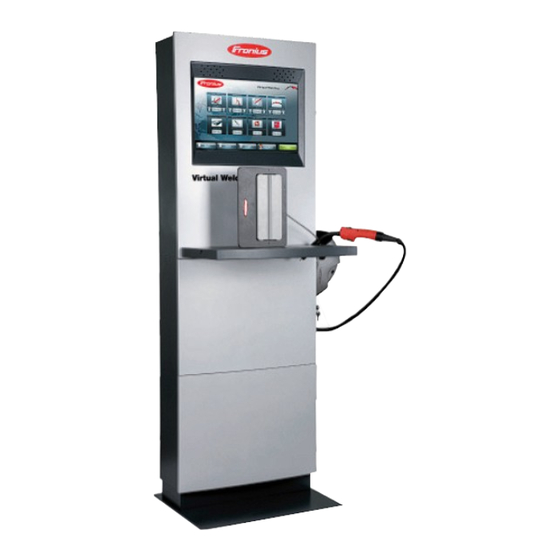
General Device concept Virtual Welding provides a realistic simula- tion of manual MIG/MAG welding and ma- nual metal arc welding, as well as other processes. True-to-scale 1:1 models of welding torches, electrode holders and workpieces are used for the different weld seam profiles. -
Page 22: Proper Use
different weld seam profiles in a wide variety of welding positions allows the user to broad- en their welding skills. The visualisation shows how the weld seam is created depending on the situation. This means that the user always has a clear view of the results of their own work. They can also assess their own results, put together study programmes or compete with other weld- ers. -
Page 23: System Components
Safety symbols on the rating plate Incorrect operation or poorly executed Do not dispose of used devices with do- work can cause serious injury or dam- mestic waste. Dispose of them accord- age. The device may only be installed, ing to safety rules. repaired and maintained by trained and qualified personnel. - Page 24 Headband for VR glasses Welding helmet (optional) The new version of the VR glasses is requi- red for Virtual Welding systems starting with serial number 22216701 onwards. To use the new VR glasses with Virtual Welding systems up to and including serial...
- Page 25 Work table Workpiece holder Workpiece single-V butt weld layer 1 Workpiece single-V butt weld layer 2 Workpiece fillet weld Workpiece pipe Housing of system components in the StandUp terminal: The StandUp terminal is supplied with two keys in a plastic pouch. One key locks the upper part containing the technology.
- Page 26 Housing of system components in the carrying case for the MobileCase: The MobileCase is contained in a robust carrying case. As well as the MobileCase, this also includes a storage space for the system components.
-
Page 27: Controls, Connections And Mechanical Components
Controls, connections and mechani- cal components... -
Page 29: Touchscreen And Sensor
Touchscreen and sensor General Due to software updates, you may find that your device has certain functions that are not described in these operating instructions or vice versa. Certain illustrations may also differ slightly from the actual controls on your device, but these controls function in exactly the same way. -
Page 30: Control Elements And Connections
Control elements and connections StandUp terminal In the following illustrations, the controls and connection sockets (1) to (4) are located in controls and con- the intermediate area between the upper and lower parts of the StandUp terminal. Con- nection sockets nection sockets (5) to (8) are located on the back of the StandUp terminal. -
Page 31: Controls And Connection Sockets On The Mobilecase
Controls and con- The controls and connection sockets illustrated below are located on the right side panel nection sockets of the MobileCase. on the Mobile- Case Function VR glasses connection socket for connecting the data cable of the VR glasses Sensor With an authorisation card: Touch once:... -
Page 32: Mains Switch With Mains Connection
Connection socket for the helmet sensor or filler material sensor for connecting the sensor cable of the welding helmet for connecting the sensor cable of the filler material (TIG) Connection socket for the workpiece sensor for connecting the sensor cable of the workpiece holder Mains switch with The mains switch with fuse and mains connection is located on the back of the StandUp mains connection... -
Page 33: Installation And Commissioning
Installation and commissioning... -
Page 35: Before Installation And Commissioning
Before installation and commissioning Safety WARNING! Work that is carried out incorrectly can cause serious injury and damage. The device may only be installed by trained personnel in accordance with the relevant na- tional and international standards. WARNING! Operating the equipment incorrectly can cause serious injury and damage. Do not use the functions described until you have thoroughly read and understood the fol- lowing documents: ►... - Page 36 Do not set up the device ..close to vital facilities such as: emergency exits fire extinguishers first-aid cabinets ... close to heat sources such as: radiators air-conditioning units sun terraces strong sunlight ... in areas subject to heavy environmental stress, such as: smoke and dirt rain and moisture strong magnetism or radio waves...
-
Page 37: Installation
Installation StandUp termi- WARNING! nal: Installation and fixing A device that topples over can easily kill someone. Set up the device in a dry and enclosed environment on a firm, supportive, horizontal sur- face, making sure it is stable. Trained personnel must fasten the StandUp terminal to the wall or anchor it firmly to the floor using the holders provided. -
Page 38: Standup Terminal: Installing System Components
StandUp termi- On the StandUp terminal, remove the work table and allow it to engage in the holder nal: Installing provided for that purpose in front of the screen system compo- Connect the system components (1) - (3) to the connection sockets in the transitional nents area between the upper and lower parts of the StandUp terminal as shown: Description... -
Page 39: Mobilecase: Setting Up
Function LAN network cable if necessary MobileCase: Set- WARNING! ting up A device toppling over could easily kill someone. Set up the device in a dry and enclosed environment on a stable and horizontal surface. NOTE! There is a danger of incorrect operation if any metallic objects are in the vicinity. There must be no metallic objects in the immediate vicinity of the device. -
Page 40: Mobilecase: Installing System Components
Place the MobileCase in the desired position Engage the work table on the front of the MobileCase Take the welding torch, the welding helmet and the workpiece holder out of the carrying case. MobileCase: In- Connect the system components (1) - (3) to the right side panel of the MobileCase as stalling system shown: components... -
Page 41: Connecting The Vr Glasses
The VR glasses must be connected when starting up the Virtual Welding system. If the VR glasses are connected during operation, restart the Virtual Welding system in or- der to initialise the VR glasses. The VR glasses can only be initialised if they are turned off... -
Page 42: Connect The Mains Cable And Switch On The Device
Terminal connecting plate MobileCase connecting plate On the Virtual Welding system Connect the data cable from the VR glasses to the VR glasses connection socket (DVI) (1) Connect the supply cable from the VR glasses to the USB connection socket (2) - Page 43 Plug the mains cable into the connecti- on socket (1) Plug the mains cable into a correctly earthed socket Set the mains switch (2) to the "I" posi- tion NOTE! Hemisphere tracking must be carried out every time the system is started. Detailed information about calibration can be found in the "Terminal management"...
-
Page 44: Display Types
Display types Display types: Depending on which display types are used, individual wiring of the connecting plate may Overview be necessary. The standard configuration as illustrated in the connection diagram on the next page allows the following display types without changing the wiring: Touchscreen as the only display VR glasses as the external display in addition to the touchscreen If the wiring is modified as described in the "External monitor or projector"... - Page 45 Disconnect the VGA cable from the monitor to the computer box (graphics card) at po- sition (1) Connect the optional DVI/VGA distributor (43,0004,4492) (2) to the now vacant VGA connection socket on the computer box (graphics card) at position (1) Connect the VGA cable from the monitor (3) to the free VGA connection socket on the optional DVI/VGA distributor (2) Route the VGA/DVI adapter cable (4) into the cable channels as shown in the "Display...
-
Page 46: Start-Up
Copy the file attached to the e-mail to the USB flash drive supplied when you pur- chased the Virtual Welding-System Update the Virtual Welding system to the latest software version - you will find detailed information on this in the "Update" section... - Page 47 "Technical settings menu item", "Choose model" subsection When completing this step, teach-in at least one authorisation card for administrators The Virtual Welding system is now fully functional.
-
Page 49: Terminal Management
Terminal management... -
Page 51: Accessing "Terminal Management
Scan a valid authorisation card using the sensor provided, see the "Touchscreen and Sensor" section on page or the "Operating elements and MobileCase connections" section on page 31. by pressing the Fronius logo: Touch the Fronius logo in this sequence: – left, right – left, right –... -
Page 52: Overview
A detailed explanation of how to change the pre-set code can be found in the "Additional settings" - "Management code settings" section on page 123. Terminal management allows complete course management for Virtual Welding systems available on the network. Overview... -
Page 53: Curriculum
Curriculum Curricula All currently available curricula are listed under the function "Curriculum". The manufactur- er offers ready-made, recommended curricula designed for optimum teaching results. The "Settings" function allows you to view the training courses and tasks at any time. It is possible to create curricula for all welding processes. The options can be limited according to the welding process, for example: "All"... - Page 54 Touch "New curriculum". A selection window appears: "Create a new curriculum / add trainings". Touch "Add training". The "Add training" button allows you to define any number of training courses. After you touch "Add training", you are presented with an overview of the available training parame- ters.
-
Page 55: Mig/Mag Tasks
The "Info" buttons provide information about the available tasks. The tasks can be activat- ed and deactivated whenever required. This allows you to create an individually tailored training course. The threshold indicates the performance level (accuracy) in % below which the colour of the display elements explained below changes from green to yellow. -
Page 56: Rod Electrode Tasks
Always choose the stick out of the welding torch relative to the workpiece so that the dis- tance arrow stays green and the torch tip is always inside the target circle. In addition to the welding speed and stick out, the trainee also practises guiding the weld- Speed / Stick out / Po- ing torch with the torch in the correct position. - Page 57 The trainee practises igniting the rod electrode at the correct tilt angle and following the Ignition specified ignition sequence. The longer of the two rod electrodes is required for this. The first step is a course unit on the basic sequence of movements that does not involve the VR glasses.
-
Page 58: Tig Tasks
Always choose the arc length from the rod electrode tip relative to the workpiece so that the distance arrow stays green and the rod electrode tip is always inside the target circle. In addition to the welding speed and arc length, the trainee also practises guiding the rod Speed / Arc length / electrode at the correct tilt angle. -
Page 59: Robotics Tasks
Robotics tasks The following tasks are available for the Robotics welding process: The Robotics tasks are similar to MIG/MAG tasks. See here for detailed information. The trainee practises guiding the welding torch at the correct speed and in the correct po- Travel Speed sition. - Page 60 Enter the name of the training course you have just created in the input window Touch "Next" to save the training course To add further training courses, touch "Add training" Repeat the process described above Once all training courses have been created, touch "Next" An input window with a virtual keyboard appears again, in which you name and save the curriculum with the individually defined training courses.
- Page 61 Enter the name of the curriculum in the input window Touch "Next" to save the curriculum The saved curriculum appears in the curriculum overview on the "Own templates" tab.
-
Page 62: Courses
Courses Courses All available courses in the Virtual Welding system are displayed under Courses. These are divided into activated and deactivated courses. The courses can be classified by welding process, for example: "All" "Metal active gas welding" ("Metal active gas welding") "Manual metal arc welding"... - Page 63 A list appears showing all available curricula, from which a course may be derived. To select a curriculum, touch the "Use" button next to the curriculum you want An overview appears showing all training courses in this curriculum. The course which you are about to name should be given a name that relates to the target group and the course year.
-
Page 64: Ghost
Ghost Ghost The "Ghost" button allows you to create "Variable Ghosts". The Variable Ghost is an aid which helps the trainee to guide the welding torch or electrode holder correctly by means of colours and direction arrows. The Variable Ghost allows the trainee to enter optimum settings based on his own judgement. - Page 65 Weld position e.g.: PF Layer e.g.: Layer 2 Filler material e.g.: G3 Si1 with a diameter of 1.2 mm Power supply e.g.: TPS 500i Welding torch e.g.: MTW 500i in 2-step mode Material type / thickness e.g.: S 235 JR with 10 mm thickness Arc Type e.g.: Dip transfer arc The arrow keys next to the "Details"...
-
Page 66: Ghost: Defining The Record Grid And Welding Speed
In the input window, enter the name of the Variable Ghost (e.g. name of trainer) Touch "Next" to save the name of the Variable Ghost Ghost: Defining Next you define the record grid by entering the steps for each workpiece. It may take a the record grid while for the corresponding window to appear. -
Page 67: Ghost: Executing Reference Welding
Use the arrow keys to set the desired welding speed The welding speed corresponds to the welding torch rate which the trainee must adhere to in the longitudinal direction. The resulting welding time appears in the field underneath. Choose "Next" to save the welding speed and go to the dialogue box for starting ref- erence welding Ghost: Executing NOTE! -
Page 68: Ghost: Defining The Optimal Oscillation
Press the torch trigger Execute the reference weld, matching the periodic welding torch movements as close- ly as possible to the previously defined record grid, as shown in the illustration below For better guidance, unobtrusive lines indicate the correct welding speed. The reference weld can be started at any point on the workpiece. - Page 69 Use the slider or arrow keys to move to the starting point of the optimal oscillation The optimal oscillation does not have to be very long, as it can be multiplied later on to form a complete weld seam. To obtain the required dwell times at the edges, the optimum start and end point should be in the centre.
-
Page 70: Ghost: Adjusting The Number Of Movement Steps And Welding Speed
Ghost: Adjusting The number of steps per workpiece specifies how many defined, periodic welding torch the number of movements the trainee must complete in order to execute the weld seam correctly. If only movement steps a short sequence was previously chosen as the optimal oscillation, the small number of and welding movement steps can now be increased up to 125. -
Page 71: Ghost: Preview
Ghost: Preview Select "Preview" to see what the welding process will provisionally look like. For example, after setting the number of steps per workpiece, select the "Preview" but- Use the slider or arrow key to move to the point from which you want to start the weld- ing process Touch the cross symbol to go back to the setting last selected Ghost: Setting... - Page 72 Choose "Next" to save the stick-out and move on to adjusting the welding torch posi- tion Use the arrow keys to set the desired tilt angle of the welding torch The position value extends from 45° backwards to 45° forwards and permits a tilt angle of -45°...
-
Page 73: Closing The Ghost
Closing the Ghost Choose "Finish" to finally confirm the settings A window with a virtual keyboard then appears in which you can enter a description for the Variable Ghost. Enter a brief description of the Variable Ghost in the input window Touch "Next"... - Page 74 To delete a Ghost: Select the "deactivated" tab Touch "Delete" Enter the following code: "12111977" In Virtual Welding robotics, a distinction is made between "Polygon" and "Cycles" when creating a Ghost: "Polygon": Enables a completely free path to be traced (inscription, etc.) "Cycles":...
-
Page 75: Terminals
The "Terminals" function allows you to assign a predefined training course to all Virtual Welding systems available on a network. It is possible either to assign the same training course to all Virtual Welding systems or to assign individual training courses to specific Vir- tual Welding systems. - Page 76 You will then see a list of the trainings of the selected course. Use the "Details" button to obtain information about the training content, if required Touch "Use" to select the training course to be assigned to the Virtual Welding system or to all Virtual Welding systems...
-
Page 77: Terminal Management - Additional Settings
Terminal management - Additional settings... -
Page 79: Additional Settings - Overview
Additional settings - Overview Additional set- Selecting the "Additional settings" button will make more customisation options for the Vir- tings - Overview tual Welding system available in the following tab: Settings Settings - activate modes Settings - activate VR glasses Coursemode General Training... - Page 80 Calibration Calibration - system calibration Calibrate MIG/MAG welding torch Note on calibrating a TIG welding torch Calibrate camera settings Calibrate hemisphere tracking Miscellaneous Licensemanager Quiz - overview Activate / deactivate available quiz Change active quiz Administrate quiz Change robot manufacturer...
-
Page 81: Settings
Press the "apply" button The system leaves terminal management, the selected mode is activated. Settings - activat- If the VR glasses are connected to the Virtual Welding system, they can be activated or ing VR glasses deactivated using the "VR - glasses" function. -
Page 82: Course Mode
To enter course mode, proceed as described in the "Terminal management" section under "Additional settings". On the touchscreen to the right of the Fronius logo you will see the name of the logged-in welder of the course... - Page 83 To obtain details of the defined welding parameters and learn more about welding: Select the "Details" buttons Touch "Next" to enter the exercise overview An overview of all the exercises defined by the trainer appears: This overview can contain up to five exercises of the following type: Speed Speed / Stick out Speed / Stick out / Position...
- Page 84 corresponding image on the touchscreen is an upward movement from the workpiece sur- face. If the welding torch enters the area of transition to the mirror image, a flicker effect may occur. The trainee practises guiding the welding torch at the correct speed and in the correct po- Travel Speed sition.
- Page 85 The first time a training course is started, only the first exercise is possible due to the de- Further procedure for fined threshold. The threshold is a limit which indicates how many percent of an exercise all exercises must be completed in order to move on to the next exercise. The percentage is relative to the maximum number of points for the relevant task and sub-task.
-
Page 86: Ranking List
If one or more results are shown in red or yellow, the threshold is not reached and the ex- ercise must be completed again. If the Virtual Welding system has already been logged into, the best welding result appears in the ranking list. If the system has not been logged into, log-in takes place upon saving the welding result, which then likewise appears in the ranking list. - Page 87 Touch the "Back" button to exit the ranking list currently selected. To export a ranking list, proceed as follows: Exporting a ranking Plug into the system the USB flash drive onto which the course will be exported list In terminal management touch "Courses" Touch "Settings"...
-
Page 88: Profile
Get an overview of the current ranking list placements ("Ranking lists") To access the profile it is necessary to log on to the Virtual Welding system. If you have not logged on in person, the log-on process starts automatically when you try to access the profile. -
Page 89: Log-In And Registration
Log-in and regis- To be able to use all functions and advantages of the Virtual Welding system, it is neces- tration sary to register with the system. After touching the "Login" button you can create your own profile, which is password-protected. - Page 90 Enter a user name and a memorable password Touch "Next" You are invited to create a personal profile. Select "Yes" This opens an input window in which you can enter the following details: First name Last name E-mail address...
-
Page 91: Select Language
The log-in and registration process is now complete. Your first name and surname appear on the touchscreen to the right of the Fronius logo. The "Login" button changes to "Logout". Use this button to log out of the Virtual Welding system. - Page 92 "Other Settings menu item" under "Language settings". Note: Virtual Welding is available in many languages, but only eight languages can be se- lected for each country configuration (dongle). Of these languages, six can be defined for...
-
Page 93: Showroom Mode
Select the "Details" buttons. Select "Start" to start the wizard The Virtual Welding system now runs through the virtual practice tasks. First of all, a weld seam is created without any prior training. This simulation of a weld seam is followed by exercises for speed, stick out and welding torch position. -
Page 94: Training
Training Training allows you to carry out some initial targeted exercises on the Virtual Welding sys- tem. Touch "Training" This opens a window containing the parameter overview. To obtain details of the defined welding parameters and learn more about welding: Select the "Details"... -
Page 95: Open Mode
Open mode General Open mode is used to demonstrate the Virtual Welding system. All the available welding parameters and exercises can be selected without any training plan. In this mode it is not possible to save or archive the scores obtained. - Page 96 Metal active gas welding process To obtain details of the defined welding parameters and learn more about welding: Select the "Details" buttons Touch "Next" to enter the exercise overview The exercise overview shows all available exercises. Before touching "Start" to begin the desired exercise: Select "Info"...
- Page 97 After completing the exercise, touch the "Playback" button to: analyse the welding process you have just carried out view the achieved result repeat the welding process return to the exercise overview Touch the "Back" button to exit the welding environment When you exit the welding environment with the "Back"...
-
Page 98: Calibration
Calibration Calibration - sys- System calibration allows you to calibrate the welding torch, the electrode holder, etc rela- tem calibration tive to the overall system, depending on the welding process. On the "Calibration" tab, touch the "Start" button next to "location adjustment" Select the appropriate calibration process depending on the welding processes avail- able Welding torch calibration will be started. -
Page 99: Calibrating The Mig/Mag Welding Torch
Calibrating the Bring the welding torch to the workpiece single-V butt weld layer 1 position, as illus- MIG/MAG welding trated torch Press the torch trigger or touch "Next" - the coordinates of the position are saved Position the welding torch according to the images on the touchscreen, if necessary correct the position using the arrow keys. -
Page 100: Calibrating Camera Settings
The camera settings allow you to adjust the welding helmet sensor. This makes it possible to adapt the Virtual Welding system to the individual body size and the resulting perspec- tive. Touch the "Start" button next to "Camera Settings"... -
Page 101: Calibrating The Hemisphere Tracking
Select the required setting using the slider Touch "Save" Check the settings entered in the previous dialogue window and, if necessary, restore the factory settings by touching "Factory default" Select "Save" in the previous dialogue window to return to the terminal management screen Calibrating the Hemisphere tracking is used to establish the correct orientation for position recognition. - Page 102 Hold the welding torch or electrode holder and the welding helmet above the work ta- Touch "Next" In the next dialogue window touch "Finish" NOTE! If the calibration of the hemispheres is lost during the welding task (3D application), the calibration process can be started by pressing the Fronius ellipse (~3 seconds).
-
Page 103: Miscellaneous
TIG simulation, simulation of manual metal arc welding or robot simulation (Robotics): Serial number of hardware dongle (can be found in the "Licensemanager" dialogue window described below) Serial number of the Virtual Welding system as shown on the rating plate... -
Page 104: Quiz - Overview
The previously enabled device functions are then shown: "Installed licenses", e.g.: 91 - Fronius base: Fronius basic configuration 92 - MAG: Simulation of the MIG/MAG welding process 93 - Electrode: Simulation of the manual metal arc welding process etc. Quiz - overview... - Page 105 Touch "Export" next to the relevant quiz The standard Fronius quiz is exported in all available languages. A personalised quiz is ex- ported in the relevant language only. Once it has been exported, the quiz is saved in a pre- defined folder.
- Page 106 The Quiz Editor is saved on the USB flash drive in the "quiz" folder. Starting the quiz editor Double-click on the "QuizEditor.exe" file Opening an existing quiz for editing Click on "Open" and select the desired quiz Change the form entries for each question using the following functions: Move between the questions with the "Previous"...
- Page 107 Start by completing the form for each question Creating a new quiz When doing so, use the same procedure as for editing an existing quiz Select the "Save" button and save the quiz in the "quiz" folder on the USB flash drive; this will be the same folder that the QuizEditor was started from In the "Administrate quiz"...
-
Page 108: Change Robot Manufacturer
Touch the wastepaper basket icon next to the relevant quiz and delete it using the code "12111977" a temporarily deacti- vated quiz It is only possible to delete a personalised quiz, not the standard Fronius quiz. Launch a quiz to test Open terminal management as described in the "Terminal management" section un- knowledge der "Access"... -
Page 111: Setup Settings
Setup settings... -
Page 113: The Setup Menu
The Setup menu Overview The setup menu allows the following settings: Cluster network Other settings Language settings, country profiles, data export, etc. Technical settings Date, time, calibration, hardware test, etc. Overview of but- Below is an overview of the buttons frequently used in the setup menu tons Edit Remove... - Page 114 NOTE! Press the red Setup key to open the Setup menu on older systems with no sensor: ► Press once = access the Setup menu ► Press twice = calibrate touchscreen Depending on whether the authorisation card belongs to an administrator or a user, this opens either the full setup menu for administrators or a simplified setup menu for users.
-
Page 116: Network Menu Item
Network menu item Cluster network A cluster network allows you to create a local network within several Virtual Welding sys- tems. This makes it possible to control the entire course management of the Virtual Weld- ing systems from one master device. - Page 117 To declare the selected system as the master, place a tick against "Master" To open the keyboard for entering a name, touch the "Edit" button to the right of the name input field Give the Virtual Welding system a name of your choosing. This will make it easier to identify the system...
- Page 118 Now that you have finished entering the cluster settings for the master, you can enter the Slave "slave" settings. It is necessary to carry out the following steps on all Virtual Welding sys- tems connected via routers: To activate the slave system, place a tick against "Active"...
- Page 119 In the password input field, enter the password previously defined in the master screen, in the same way as described for the name Touch the "Save" button to save the settings Repeat steps 1 to 7 for all Virtual Welding systems which you want to include in a local cluster network. NOTE! To guarantee fault-free communication between the master and the slave systems, it is important to carry out all the described steps carefully.
-
Page 120: Other Settings Menu Item
The "Other settings" area includes language settings, country profiles and much more. Restricted settings for the "User" profile: Licence list The licence list contains the licences currently available on the Virtual Welding system, in- cluding additional information (such as licence name, description, etc.). -
Page 121: Exporting
Exporting The setup settings for the Virtual Welding system can be exported to a USB stick. Follow these steps: Plug a normal USB stick into the USB connection socket (1) of the Virtual Welding sys- Touch the "Export" button... - Page 122 Touch: "All data" - the following settings and data are exported: Courses Curriculum Profiles Ranking lists (without playback function) Settings for the Variable Ghost "Ghost" - only the settings for the Variable Ghost are exported NOTE! The export function can be used to carry out regular data backups. Back up data at least once a week to avoid any loss of data.
-
Page 123: Management Code
Touch the tick symbol to confirm Management Management code allows you to change the default code (1234) to a 4-digit code of your code own choosing. NOTE! Be careful not to lose the code. Never forget the code you entered, otherwise you will no longer be able to define important settings. -
Page 124: Importing
Risk of data loss: When you import data, the settings saved on the terminal are overwritten. Selected settings for the Virtual Welding system can be imported from a USB stick. Plug a normal USB stick into the USB connection socket (1) of the Virtual Welding sys- Touch the "Import" button Touch: "All data"... -
Page 125: Language Settings
Touch the tick symbol to confirm Language set- A country version of the Virtual Welding software can be provided in up to 8 languages, of tings which 6 languages can be activated. The language settings specify which languages can be selected by the user. -
Page 126: Country Profiles
One of the active languages is defined as the standard language. This means that, when the Virtual Welding system has not been used for a certain period of time, the Virtual Weld- ing software reverts to that language. In the "Active" list, touch the box of the desired language to activate or deactivate that... -
Page 127: Reset
In the "Select profile" box, touch the button for the desired profile Touch the "Save" button to save the changes Reset The "Reset" button allows you to return the Virtual Welding system to the factory settings. NOTE! Risk of data loss. -
Page 128: Sensor Registration
Sensor registra- Two authorisation cards are supplied with each Virtual Welding system. They are used to tion access terminal management or the setup menu in order to enter settings. When the sys- tem is first installed, the authorisation card can be used to create an administrator or a user. - Page 129 To add a new authori- Have the relevant authorisation card to hand sation card for an ad- In the "Add sensor" area, touch "Administrator" ministrator When the relevant request appears on the touchscreen, hold the authorisation card above the sensor Confirm the message that appears by touching the tick icon Have the relevant authorisation card to hand To add a new authori-...
- Page 130 To remove an authori- Have the relevant authorisation card to hand sation card for a user In the "Remove sensor" area, touch "User" When the relevant request appears on the touchscreen, hold the authorisation card above the sensor Confirm the message that appears by touching the tick icon To remove all authori- In the "Remove sensor"...
-
Page 131: Technical Settings Menu Item
Technical settings menu item Overview The "Technical settings" area covers technical settings, information and tests. Restricted settings for the "User" profile: Setting the date Touch the "Adjust date/time" button to open the input window for setting the date, time and time and time zone. -
Page 132: Showing The Nsb Number
Touch the "Save" button to save the setting Showing the NSB The NSB number is the version number of the Virtual Welding software and uniquely iden- number tifies a Virtual Welding software version, for example in the case of support queries. -
Page 133: Test Screen
Test screen The test screen allows you to check the screen settings. Touch the "Test-screen" button Opening the test screen Touch any area of the touchscreen display Every touch of the touchscreen display causes the next test screen to appear. Closing the test Touch the cross symbol screen... -
Page 134: Brightness Of Glasses
VR glasses and modify other display parameters, such as contrast. Choosing the The "Choose model" / "TerminalKind" entry is used to select whether the Virtual Welding model system is in a terminal or a MobileCase, and whether a "Helmet" / "Headband" or "Breast- clip"... -
Page 135: Scandisk
Touch the "ScanDisk" button Touch the "run ScanDisk" button Touch "Save" ScanDisk will run the next time the Virtual Welding system is started As long as "run ScanDisk" is selected, it will run the next time the Virtual Welding system is started. -
Page 136: Calibrating The Touchscreen
Calibrating the NOTE! touchscreen Risk of inaccurate calibration. Calibration must be carried out at normal ambient temperature and with the Virtual Welding system at normal operating temperature. To calibrate the touchscreen: Touch the "Calibrate touchscreen" button Follow the instructions and touch the successively appearing cross hairs as close as... -
Page 137: Touchscreen Test
Run your finger over the touchscreen and check whether the mouse pointer follows: If the touchscreen calibration was successful: Touch the tick symbol to confirm If the result of the touchscreen calibration is not satisfactory: Touch the button next to the tick symbol to repeat the touchscreen calibration Touchscreen test The touchscreen test is used to check the touchscreen calibration. -
Page 138: Adjusting The Volume
Carrying out the touchscreen test Select the "Touch screen test" button Touch any area of the touchscreen display: A square shows where the finger touch was registered Touch the cross symbol to exit the touchscreen test Adjusting the vol- The "Set volume" function is used to adjust the volume for the application itself ("Volume application") advertisement ("Volume advertisement") minimum volume of the application ("Minimum volume for terminal") - Page 139 Setting and testing the volume: Touch the "Set volume" button Use the sliders to set the desired volume. – While doing so, touch one of the sound buttons (loudspeaker symbols) or music buttons (note symbols) - a test sound or test music will be heard Touch the "Save"...
-
Page 141: Troubleshooting And Maintenance
Troubleshooting and maintenance... -
Page 143: Troubleshooting
Work that is carried out incorrectly can cause serious injury or damage. The activities described below must only be carried out by trained and qualified personnel. Observe the safety rules in the Virtual Welding operating instructions. WARNING! An electric shock can be fatal. -
Page 144: Fault Diagnosis
"Terminal management" section under "Additional settings". Positioning of the welding torch or electrode holder differs from the image appear- ing in the screen Cause: The welding torch or electrode holder is wrongly calibrated Remedy: Carry out Fronius system calibration... - Page 145 Cause: There is another Virtual Welding system in the immediate vicinity Remedy: Increase the distance from the other Virtual Welding system to at least 4 me- tres Cause: There are objects that emit radiation (mobile telephones etc.) in the immedi-...
- Page 146 USB dongle not plugged in or is plugged into the wrong USB port Remedy: Plug USB dongle into a different USB port and restart the Virtual Welding sys- NOTE! The dongle should always be connected alone via a USB bank!
-
Page 147: Care, Maintenance And Disposal
Care, maintenance and disposal General Under normal operating conditions, the device requires only a minimum of care and main- tenance. However, it is essential to observe certain points to ensure that the device gives reliable service for many years. Safety WARNING! An electric shock can be fatal. -
Page 148: Update
The production number can be seen on the rating plate of the Virtual Welding system ("Prod. No." - the position of the rating plate is shown in the section "Warning notices on the device" in the chapter "General"):... - Page 149 If the VR glasses are to be connected: Connect the data cable from the VR glasses to the DVI connection socket Connect the supply cable from the VR glasses to the USB connection socket Move the mains switch to the "I" position...
-
Page 151: Appendix
Appendix... -
Page 153: Technical Data
Technical data Special voltages For devices designed for special voltages, the technical data on the rating plate applies. Virtual Welding Mains voltage +/- 10 % 110 V - 230 V terminal and Mo- Grid frequency 50/60 Hz bileCase Mains fuse 3.15 A... -
Page 154: Spare Parts List: Virtual Welding
Spare parts list: Virtual Welding Mobilecase 42,0411,0107 42,0411,0103 42,0411,0086 42,0411,0114 42,0411,0066 42,0411,0087 42,0411,0102 4,100,621 42,0411,0072 before 01.06.2013 42,0411,0074 42,0201,7271 42,0411,9023 after 01.06.2013 42,0411,0089 until SN 24203464 - 42,0411,0068 after SN 24203465 - audio amplifier+ RFID-reader 42,0411,0098 42,0411,0088 42,0411,0099 41,0007,0116... - Page 155 StandUp Terminal 42,0411,0067 42,0411,0113 42,0411,0109 42,0411,0115 42,0411,0110 42,0411,0112 42,0411,0111...
- Page 156 StandUp Terminal 42,0411,0102 42,0411,0086 42,0411,0087 42,0411,0114 42,0411,0089 42,0411,0098 42,0411,0072 41,0007,0007 42,0411,0099 42,0201,7271 before 4,100,621 Prod.Nr.: F2561 xxx-xx-xx 42,0411,0074 42,0411,9023 after Prod.Nr.: until SN 24203464 - 42,0411,0068 F2562 xxx-xx-xx after SN 24203465 - audio amplifier + RFID-reader 42,0411,0088 41,0007,0116...
- Page 157 42,0411,9021 after 01.12.2011 42,0411,9037 42,0411,9038 44,0350,3614 42,0411,0070 before 01.12.2011 - 42,0411,0078 42,0411,0084 after 01.12.2011 - 42,0411,0132 42,0411,0075 42,0411,0071 42,0411,0076 42,0411,0085 Headband 42,0411,0152 42,0411,0069 Sens.1 42,0411,0091 Sens.2 42,0411,0092 Sens.3 42,0411,0093 Sens.4 42,0411,0094 Sens.5 42,0411,0095 Sens.6 42,0411,0096 Sens.7 42,0411,0097 Sens.8 42,0411,0100 Euro 42,0411,0150 42,0411,0116 42,0411,0117...
- Page 158 4,035,909 Virtual Welding MIG Torch 2.3m 32,0405,1027 40,0001,0302 42,0402,1005 43,0004,5256 42,0405,1021 42,0405,0790 40,0001,0302 42,0405,1029 42,0405,1196 32,0402,1008 4,070,900 40,0001,0001 32,0405,0358 42,0401,0936 43,0002,0386 42,0401,1061 42,0405,0780 42,0404,0381 42,0100,1231 xx) Specify the length required 42,0100,1230...
- Page 159 4,035,977 Electrode Holder Virtual Welding 2,3m 42,0405,0383 42,0100,1375 42,0100,1374 4,070,803 42,0100,0851 42,0100,0853 42,0300,2499 42,0100,0854 42,0100,0852 44,0350,3612 42,0405,0790 42,0401,1061 42,0100,1363 44,0350,3613 40,0001,0302 43,0004,5256 xx) gewünschte Länge angeben xx) Specify the length required xx) Indiquer la longueur désirée xx) Indicar la longitud deseada...
- Page 160 4,035,986 Virtual Welding TIG torch hand 2,3m + filler rod 4,035,996 Virtual Welding TIG torch hand 2,3m 44,0350,4246 Virtual Welding filler rod 44,0350,2175 44,0350,2174 44,0350,0337 4,070,803 42,0100,1504 42,0100,1499 42,0100,1166 42,0401,1061 Virtual Welding filler rod - 44,0350,4246 40,0001,0302 42,0404,0381 42,0100,0601 42,0100,0603 43,0004,5256 xx) gewünschte Länge angeben...
- Page 161 4,051,103 Virtual Welding Roboter 42,0405,0559 42,0100,1452 40,0001,0541 42,0401,0314 42,0300,3102 42,0407,0702 42,0100,1453 42,0100,1451 42,0100,1455 42,0401,0974 42,0401,0314 42,0407,0706 42,0405,0780 42,0405,0790 42,0100,1058 42,0401,1061 4,070,900 42,0404,0381 42,0100,1456 42,0100,1231 42,0100,1230 43,0004,5256 42,0405,0790 xx) gewünschte Länge angeben xx) Specify the length required xx) Indiquer la longueur désirée...
-
Page 162: Glossary
Glossary ADSL ADSL stands for "Asymmetric Digital Subscriber Line" and is the commonest form of DSL. Far more data is usually downloaded onto a computer than is sent, hence the asymmetrical design of the sending and receiving channels. Speeds of up to 8 Mbps (megabits per sec- ond) are possible for receiving and up to 1 Mbps for sending. -
Page 163: Gprs
GPRS GPRS stands for "General Packet Radio Service". GPRS is a data transfer technology which is based on the Internet protocol (IP) for GSM mobile phone networks. While conventional GSM networks reach transfer speeds of not more than 9.6 Kbps (kilo- bits per second), speeds of well over 100 Kbps are theoretically possible with GPRS. - Page 164 RAM stands for "Random Access Memory" and refers to a computer's working memory. Unlike a hard disk, RAM does not provide permanent storage. The data remains in the RAM until the power supply is disconnected. S0 bus for ISDN The S0 bus is an internationally standardised 4-wire bus which is connected downstream of the NTBA (Network Termination for Basic Access) adapter and is responsible for the connection of ISDN terminal devices.
- Page 165 WEP stands for "Wired Equivalent Privacy" and is a standard for the encryption of signals on a wireless network. A WEP encryption code is used to encrypt the data. The higher the bit-rate, the greater the protection.
- Page 168 FRONIUS INTERNATIONAL GMBH Froniusstraße 1, A-4643 Pettenbach, Austria E-Mail: sales@fronius.com www.fronius.com Under www.fronius.com/contact you will find the addresses of all Fronius Sales & Service Partners and locations...
Need help?
Do you have a question about the Virtual Welding and is the answer not in the manual?
Questions and answers