Table of Contents

Related Manuals for Fronius VR 1500-M


Summary of Contents for Fronius VR 1500-M
- Page 1 Perfect Welding / Perfect Charging / / Solar Energy Operating Instructions VR 1500-M Wire-feed unit 42,0426,0008,EN 001-05022020 Fronius prints on elemental chlorine free paper (ECF) sourced from certified sustainable forests (FSC).
- Page 3 Thank you for the trust you have placed in our company and congratulations on buying this high-quality Fronius product. These instructions will help you familiarise yourself with the product. Reading the instructions carefully will enable you to learn about the many different features it has to offer.
-
Page 5: Table Of Contents
Contents Safety rules ..............................General ..............................Proper use ............................Environmental conditions........................Obligations of the operator........................Obligations of personnel ........................Mains connection ..........................Protecting yourself and others ......................Danger from toxic gases and vapours ....................Danger from flying sparks ........................Risks from mains current and welding current..................Meandering welding currents........................ - Page 6 Set the contact pressure ........................Care, maintenance and disposal ....................... General remarks ........................... Every start-up............................Every 6 months ............................. Disposal ..............................Troubleshooting ............................"Wire end" error message........................"Wire end" special function ........................Troubleshooting ............................ Error reset ............................. Technical data............................VR 1500-M............................
-
Page 7: Safety Rules
Safety rules General The device is manufactured using state-of-the-art technology and according to recognised safety standards. If used incorrectly or misused, however, it can cause: injury or death to the operator or a third party, damage to the device and other material assets belonging to the operating company, inefficient operation of the device. -
Page 8: Obligations Of The Operator
Ambient temperature range: during operation: -10 °C to + 40 °C (14 °F to 104 °F) during transport and storage: -20 °C to +55 °C (-4 °F to 131 °F) Relative humidity: up to 50% at 40 °C (104 °F) up to 90% at 20 °C (68 °F) The surrounding air must be free from dust, acids, corrosive gases or substances, etc. -
Page 9: Danger From Toxic Gases And Vapours
Suitable protective clothing must be worn when working with the device. The protective clothing must have the following properties: Flame-resistant Insulating and dry Covers the whole body, is undamaged and in good condition Safety helmet Trousers with no turn-ups Protective clothing refers to a variety of different items. Operators should: Protect eyes and face from UV rays, heat and sparks using a protective visor and reg- ulation filter Wear regulation protective goggles with side protection behind the protective visor... -
Page 10: Danger From Flying Sparks
Flammable vapours (e.g. solvent fumes) should be kept away from the arc's radiation area. Close the shielding gas cylinder valve or main gas supply if no welding is taking place. Danger from fly- Flying sparks may cause fires or explosions. ing sparks Never weld close to flammable materials. -
Page 11: Meandering Welding Currents
Operating the device on a grid without a ground conductor and in a socket without a ground conductor contact will be deemed gross negligence. The manufacturer shall not be held liable for any damage arising from such usage. If necessary, provide an adequate earth connection for the workpiece. Switch off unused devices. -
Page 12: Emf Measures
either radio or television receivers). If this is the case, then the operator is obliged to take appropriate action to rectify the situ- ation. Check and evaluate the immunity to interference of nearby devices according to national and international regulations. Examples of equipment that may be susceptible to interfer- ence from the device include: Safety devices Power, signal and data transfer lines... -
Page 13: Requirement For The Shielding Gas
Never touch the workpiece during or after welding - risk of burns. Slag can jump off cooling workpieces. The specified protective equipment must therefore also be worn when reworking workpieces, and steps must be taken to ensure that other people are also adequately protected. Welding torches and other parts with a high operating temperature must be allowed to cool down before handling. -
Page 14: Danger From Escaping Shielding Gas
Protect shielding gas cylinders containing compressed gas from excessive heat, mechan- ical impact, slag, naked flames, sparks and arcs. Mount the shielding gas cylinders vertically and secure according to instructions to prevent them falling over. Keep the shielding gas cylinders well away from any welding or other electrical circuits. Never hang a welding torch on a shielding gas cylinder. -
Page 15: Safety Measures In Normal Operation
Before transporting the device, allow coolant to drain completely and detach the following components: Wirefeeder Wirespool Shielding gas cylinder After transporting the device, the device must be visually inspected for damage before commissioning. Any damage must be repaired by trained service technicians before com- missioning the device. -
Page 16: Safety Inspection
(e.g. relevant product standards of the EN 60 974 se- ries). Fronius International GmbH hereby declares that the device is compliant with Directive 2014/53/EU. The full text on the EU Declaration of Conformity can be found at the following address: http://www.fronius.com... -
Page 17: General
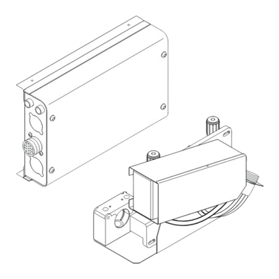
General Device concept The VR 1500-M robot wirefeed ist specially designed for use with the EA 1400 N and EA 1900 N robots. The drive plate and con- troller need to be fitted separately; the con- troller needs to be earthed separately. -
Page 18: Scope Of Delivery
Scope of delivery Lieferumfang VR 1500-M 1 x controller mounting bracket 1 x drive cover 1 x drive plate with feeder rolls 1.0 mm / trapezoid groove 1 x drive plate bracket 1 x insulation plate 1 x Controller 4 x hexagonal socket head screw M6 x 16 + washer... -
Page 19: Additional Requirements
Additional re- quirements Interconnecting cable assembly controller + accessories 1 x interconnecting cable assembly controller article number 4,047,425 (length 2,5 m) ... for EA 1400 N article number 4,047,435 (length 2,7 m) ... for EA 1900 N 2 x strain relief 6 x screw Extrude-Tite M5 x 16 You additionally require a standard interconnecting cable assembly to connect the system to the power supply. -
Page 20: Warning Notices On The Device
Warning notices on the device General Do not remove or paint over safety labels and warnings attached to the device. The sym- bols warn operators of improper useage and can help prevent serious injury and material damage. Controller Safety symbols and warning notices affixed to the device must not be removed or painted over. -
Page 21: Drive Plate
Drive plate Warning label on drive plate Welding is dangerous. The following basic requirements must be met to en- sure the equipment is used properly: welders must be sufficiently qualified use appropriate protective equipment all persons not involved in the welding process must be kept at a safe dis- tance CAUTION! Motor and gearbox become hot under normal operation Only mount insulated... -
Page 22: Options
Options Wire feeder hose To protect the filler wire from the wire holder to the VR 1500; available in various lengths. The wire feeder hose also guarantees constant wire feed. Lockable pres- For attaching a lockable pressure lever. Prevents accidental adjustment of the pressure le- sure lever for drive plate Wire end plug kit... -
Page 23: Controls, Connections And Mechanical Components
Controls, connections and mechanical components General The location of the controls, connectors, and mechanical components described in the fol- lowing section can vary depending on customer requirements. WARNING! Improper use can cause serious injury and/or material damage. Do not use the described functions until you have read and understood the following doc- umentation: ►... -
Page 24: Drive Plate
Drive plate Drive plate Welding torch connector for attaching welding torch Connector welding potential 4-roll drive Wire feed tube Shielding gas connector Controller conntector - 17-pin female Amphenol connector Connector welding torch CAT lead Detail X Drive plate bottom... -
Page 25: Assembly - Overview
Assembly - overview Safety WARNING! An electric shock can be fatal. Attaching the device to the mains during the installation setps can cause serious injury and material damage. ► Only carry out work on the device if the mains switch of the power source is in the "O" position. -
Page 26: Attaching The Vr 1500 M To The Robot
Attaching the VR 1500 M to the robot Preparation Remove screws from side panel (4 x) The side panel screws are required la- ter when attaching the VR 1500-M to the EA 1400 N robot. Side panel screws Robot side panel... - Page 27 (1) (2) CAUTION! Danger of injury due to devices falling. Work that is carried out incorrectly may re- sult in serious injury or damage to property. ► Check the seating of the screw connec- tions between the controller and the controller bracket.
-
Page 28: Attaching The Welding Torch To The Drive Plate
Attaching the Attach the strain relief (1) for the inter- welding torch to connecting cable assembly controller the drive plate to the controller bracket (2) using Ex- trude- Tite M5 x 16 screws. Use a screwdriver to open up the hose holder (3) on the controller bracket Insert the corrugated hose (4), close the hose holder (3). -
Page 29: Attaching The Welding Torch To The Drive Plate
Attaching the CAUTION! welding torch to the drive plate Danger of injury due to falling parts. Work that is carried out incorrectly may result in serious injury or damage to property. ► Check the seating of the screw connections between the drive plate and the robot. Inch welding torch cable assembly into robot arm. -
Page 30: Calibrating The Drive Plate And Controller
Calibrating the drive plate and controller General IMPORTANT! Calibrate the drive plate and controller: before commissioning each time you replace the drive plate after every wire feeder software update Failure to calibrate the drive plate and the controller will lead the power source to select the factory defaults. - Page 31 Press the „Store“ button on the power source twice (to quit the Setup menu) Engage the drive plate...
-
Page 32: Inserting/Replacing Feed Rollers
Inserting/replacing feed rollers General remarks In order to achieve optimum wire electrode feed, the feed rollers must be suitable for the diameter and alloy of the wire being welded. IMPORTANT! Only use feed rollers that match the wire electrode. An overview of the feed rollers available and their possible areas of use can be found in the spare parts lists. -
Page 33: Feeding In The Wire Electrode
Feeding in the wire electrode Insulated routing WARNING! of wire electrode to wire-feed unit Risk of serious injury and property damage or an inferior weld as a result of earth contact or short-circuit of a non-insulated wire electrode. In the case of automated applications, ensure that only an insulated wire electrode is rout- ed from the welding wire drum, large wirefeeder spool or wirespool to the wirefeeder (e.g. - Page 34 CAUTION! Danger from wire electrode emerging unexpectedly as it is being threaded. It can cause injuries. ► Wear suitable protective goggles ► Keep the tip of the welding torch away from your face and body ► Do not point the tip of the welding torch at people ►...
-
Page 35: Set The Contact Pressure
Set the contact pressure NOTE! Set the contact pressure in such a way that the wire electrode is not deformed but nevertheless ensures proper wire- feeding. Contact pressure stand- Semi-cylindrical Trapeze rolls Plastic rollers ard values rolls Aluminium 3.5 - 4.5 Steel 3 - 4 CrNi... -
Page 36: Care, Maintenance And Disposal
Care, maintenance and disposal General remarks Under normal operating conditions, the wire-feed unit requires only a minimum of care and maintenance. However, some important points must be noted to ensure that the welding system remains in a usable condition for many years. WARNING! An electric shock can be fatal. -
Page 37: Troubleshooting
Troubleshooting "Wire end" error The "wire end" error message is used for the following errors on VR 1500 series systems: message wire end overheating of power electronics motor current too high "Wire end" spe- Two options can be preset on the power source for the "wire end" error message: cial function complete welding ... -
Page 38: Technical Data
Technical data VR 1500-M Supply voltage 55 V DC Rated current Wire diameter 0,8 - 1,6 mm 0.03 - 0.06 in. Wire speed 0,5 - 22 m/min 19.69 - 866.14 ipm. Torque 4 Nm Protection controller IP 21 Protection drive plate... - Page 40 FRONIUS INTERNATIONAL GMBH Froniusstraße 1, A-4643 Pettenbach, Austria E-Mail: sales@fronius.com www.fronius.com Under www.fronius.com/contact you will find the addresses of all Fronius Sales & Service Partners and locations...
Need help?
Do you have a question about the VR 1500-M and is the answer not in the manual?
Questions and answers