
Subscribe to Our Youtube Channel
Related Manuals for Fronius VR 7000


Summary of Contents for Fronius VR 7000
- Page 1 / Perfect Charging / Perfect Welding / Solar Energy Operating Instructions VR 7000 Spare parts list VR 7000-11 Wire-feed unit VR 7000-30 VR 7000 CMT 42,0426,0015,EN 004-17012019...
- Page 3 Thank you for the trust you have placed in our company and congratulations on buying this high-quality Fronius product. These instructions will help you familiarise yourself with the product. Reading the instructions carefully will enable you to learn about the many different features it has to offer.
-
Page 5: Table Of Contents
Contents Safety rules ..............................General ..............................Proper use ............................Environmental conditions........................Obligations of the operator........................Obligations of personnel ........................Mains connection ..........................Protecting yourself and others ......................Noise emission values .......................... Danger from toxic gases and vapours ....................Danger from flying sparks ........................Risks from mains current and welding current.................. - Page 6 Care, maintenance and disposal ....................... General remarks ........................... Every start-up............................Every 6 months ............................. Disposal ..............................Technical data............................VR 7000 ..............................VR 7000-11............................VR 7000-30............................VR 7000 CMT ............................Appendix Spare parts list: VR 7000, VR 7000-11, VR 7000-30, VR 7000 CMT ............
-
Page 7: Safety Rules
Safety rules General The device is manufactured using state-of-the-art technology and according to recognised safety standards. If used incorrectly or misused, however, it can cause: injury or death to the operator or a third party, damage to the device and other material assets belonging to the operating company, inefficient operation of the device. -
Page 8: Obligations Of The Operator
Ambient temperature range: during operation: -10 °C to + 40 °C (14 °F to 104 °F) during transport and storage: -20 °C to +55 °C (-4 °F to 131 °F) Relative humidity: up to 50% at 40 °C (104 °F) up to 90% at 20 °C (68 °F) The surrounding air must be free from dust, acids, corrosive gases or substances, etc. -
Page 9: Protecting Yourself And Others
Protecting your- Anyone working with the device exposes themselves to numerous risks, e.g. self and others flying sparks and hot pieces of metal Arc radiation, which can damage eyes and skin Hazardous electromagnetic fields, which can endanger the lives of those using cardi- ac pacemakers Risk of electrocution from mains current and welding current Greater noise pollution... -
Page 10: Danger From Flying Sparks
Otherwise, a protective mask with an air supply must be worn. Close the shielding gas cylinder valve or main gas supply if no welding is taking place. If there is any doubt about whether the extraction capacity is sufficient, the measured toxic emission values should be compared with the permissible limit values. -
Page 11: Meandering Welding Currents
The electrode (rod electrode, tungsten electrode, welding wire, etc.) must never be immersed in liquid for cooling Never touch the electrode when the power source is switched on. Double the open circuit voltage of a power source can occur between the welding elec- trodes of two power sources. -
Page 12: Emc Measures
Devices in emission class B: Satisfy the emissions criteria for residential and industrial areas. This is also true for residential areas in which the energy is supplied from the public low-voltage mains. EMC device classification as per the rating plate or technical data. EMC measures In certain cases, even though a device complies with the standard limit values for emis- sions, it may affect the application area for which it was designed (e.g. - Page 13 Covers and side panels may only be opened/removed while maintenance or repair work is being carried out. During operation Ensure that all covers are closed and all side panels are fitted properly. Keep all covers and side panels closed. The welding wire emerging from the welding torch poses a high risk of injury (piercing of the hand, injuries to the face and eyes, etc.).
-
Page 14: Factors Affecting Welding Results
Factors affecting The following requirements with regard to shielding gas quality must be met if the welding welding results system is to operate in a correct and safe manner: Size of solid matter particles < 40 μm Pressure dew point < -20 °C Max. -
Page 15: Safety Measures In Normal Operation
Special regulations apply in rooms at risk of fire or explosion Observe relevant national and international regulations. Use internal directives and checks to ensure that the workplace environment is always clean and clearly laid out. Only set up and operate the device in accordance with the degree of protection shown on the rating plate. -
Page 16: Commissioning, Maintenance And Repair
(e.g. relevant product standards of the EN 60 974 se- ries). Fronius International GmbH hereby declares that the device is compliant with Directive 2014/53/EU. The full text on the EU Declaration of Conformity can be found at the following... -
Page 17: Data Protection
Devices marked with the CSA test mark satisfy the requirements of the relevant standards for Canada and the USA. Data protection The user is responsible for the safekeeping of any changes made to the factory settings. The manufacturer accepts no liability for any deleted personal settings. Copyright Copyright of these operating instructions remains with the manufacturer. -
Page 18: General
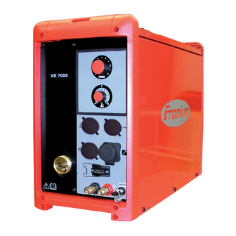
VR 7000 / VR 7000-11 / VR 7000-30 wirefeeder VR 7000 CMT wire-feed unit The wirefeeders of the VR 7000 series are designed to be used with wirespools of max. 300 mm (11.81 in.) diameter. The wirespool holder is located inside the wirefeeder housing. The wirespool is thus pro- tected from soiling. -
Page 19: Warning Notices On The Device
Warning notices The wire-feed unit has safety symbols on the rating plate. The safety symbols must not be on the device removed or painted over. The symbols warn against operating the equipment incorrectly, as this may result in serious injury and damage. Do not use the functions described here until you have fully read and understood the following documents: These operating instructions... -
Page 20: Options
VR 4000 Ci control panel option VR 4000 digital display option IMPORTANT! On the VR 7000 CMT, the optional VR 4000 Ci and VR 4000 control panels are used exclusively to display actual values. Parameters cannot be adjusted via the op-... -
Page 21: Optional Installation And Conversion Kits
Digital gas control for subsequent installation of the digital gas control 900 A installation kit so subsequent retrofitting, so that the VR 7000-11 and VR 7000-30 are suitable for a welding current of 900 A VR 7000-11 and VR 7000-30 only... -
Page 22: Controls And Indicators
Controls and indicators General WARNING! Operating the equipment incorrectly can cause serious injury and damage. Do not use the functions described here until you have fully read and understood the fol- lowing documents: ► These operating instructions ► all the operating instructions for the system components, especially the safety rules Setting parameters at control panels is only possible in manual welding mode. - Page 23 Arc length/arc-force dynamic adjuster has a different function depending on the welding process being used Correcting the arc length (during MIG/MAG pulse synergic welding, MIG/MAG standard synergic weld- ing) - = shorter arc length 0 = neutral arc length + = longer arc length Setting the welding voltage (during MIG/MAG standard manual welding) Influencing the short circuit amperage at the instant of droplet transfer...
-
Page 24: Connections And Mechanical Components
LocalNet connection standardised connection socket for system add-ons (e.g. remote control, JobMas- ter torch, etc.) Blanking cover on VR 7000, VR 7000-11, VR 7000-30 Wire buffer connection on VR 7000 CMT 4-pin amphenol socket for connecting the wire buffer Blanking cover on VR 7000, VR 7000-11, VR 7000-30 LHSB CMT drive unit connection on VR 7000 CMT for connecting the LHSB cable from the welding torch, incl. -
Page 25: Rear Of Wire-Feed Unit
Blanking cover (11) Blanking cover Optional gas economiser valve (12) Blanking cover (10) Current socket for optional installa- tion kit 900 A for VR 7000-11 and (11) VR 7000-30 (13) Bushing for compressed air (12) (14) Bushing for interconnecting hose-... - Page 26 MIG/MAG standard manual welding Job welding TIG welding with touch-down ignition MMA welding IMPORTANT! If the VR 7000 wirefeeder is connected to a TS 4000/5000 power source, MIG/MAG pulse synergic welding is not available. (19) Mode selector switch for selecting the following operating modes:...
-
Page 27: Wirefeeder Right Side
(24) (24) (23) (23) (22) (22) (21) (21) VR 7000 / VR 7000-11 / VR 7000-30 VR 7000 CMT Item Description (21) Shielding gas connection for interconnecting hosepack (22) Water flow connection (blue) for interconnecting hosepack (23) Water return connection (red) for interconnecting hosepack... -
Page 28: Placing Wire-Feed Unit On Power Source
Placing wire-feed unit on power source General The wire-feed units can be placed on the power source if a swivel pin holder is available, e.g.: "PickUp" swivel pin receptor, for use with the "PickUp" trolley "narrow" swivel pin receptor, for use with an upright console "wide"... -
Page 29: Connecting Wire-Feed Unit To Power Source
The wirefeeder is connected to the power source using the interconnecting hosepack. For the "CMT" welding process, a special CMT interconnecting hosepack with additional LHSB cable is required for connecting the VR 7000 CMT to the CMT power source. Connecting the... -
Page 30: Connecting The Welding Torch
VR 7000 CMT ... up to max 500 A NOTE! When using a welding current over 500 A, only operate wirefeeders VR 7000-11 and VR 7000-30 with Fronius welding torches that are adequately dimensioned for the welding torch F++ connection. -
Page 31: Connecting The Mig/Mag Robot Welding Torch, Connecting The Automatic Mig/Mag Welding Torch
Connecting the MIG/MAG robot welding torch, connecting the automatic MIG/ MAG welding torch MIG/MAG robot welding torch (e.g.: Robacta Drive) MIG/MAG robot welding torch with external wirefee- ding hose (e.g. Robacta Drive ext. DFS) Connecting the Control plug for wire buffer CMT drive unit... -
Page 32: Inserting/Replacing Feed Rollers
Inserting/replacing feed rollers General remarks In order to achieve optimum wire electrode feed, the feed rollers must be suitable for the diameter and alloy of the wire being welded. IMPORTANT! Only use feed rollers that match the wire electrode. An overview of the feed rollers available and their possible areas of use can be found in the spare parts lists. -
Page 33: Inserting The Wirespool, Inserting The Basket-Type Spool
Inserting the wirespool, inserting the basket-type spool Safety CAUTION! Risk of injury from springiness of spooled wire electrode. When inserting the wirespool/basket-type spool, hold the end of the wire electrode firmly to avoid injuries caused by the wire electrode springing back. CAUTION! Risk of injury from falling wirespool/basket-type spool. -
Page 35: Feeding In The Wire Electrode
Feeding in the wire electrode Feed in the wire CAUTION! electrode Risk of injury from springiness of spooled wire electrode. When inserting the wire electrode into the 4 roller drive, hold the end of the wire electrode firmly to avoid injuries caused by the wire springing back. CAUTION! Risk of damage to the welding torch from sharp end of wire electrode. -
Page 36: Set The Contact Pressure
Set the contact pressure NOTE! Set the contact pressure in such a way that the wire electrode is not deformed but nevertheless ensures proper wire- feeding. Contact pressure stand- Semi-cylindrical Trapeze rolls Plastic rollers ard values rolls Aluminium 3.5 - 4.5 Steel 3 - 4 CrNi... -
Page 37: Adjust The Brake
Adjust the brake Adjusting the NOTE! brake After releasing the torch trigger the wirespool should stop unreeling. Adjust brake if necessary. STOP STOP Design of the CAUTION! brake Risk of injury and damage from falling wirespool. To ensure that the wirespool is properly in place and that the brake works properly, fit the brake according to the following diagram. - Page 38 KLEBER, GLUE, COLLE...
-
Page 39: Fitting Wirefeeding Hose For External Wire Electrode
Fitting wirefeeding hose for external wire electrode General The wirefeeding hose option serves to protect the external wire electrode while it is being conveyed to the 4 roller drive of the wirefeeder. The wirefeeding hose is available in two versions: for steel (blue) for aluminium (white) Insulated routing... -
Page 40: Start-Up
Start-up General informa- WARNING! tion Operating the equipment incorrectly can cause serious injury and damage. Do not use the functions described until you have thoroughly read and understood the fol- lowing documents: ► these operating instructions ► all the operating instructions for the system components, especially the safety rules The wire-feed unit is commissioned by pressing the torch trigger (for manual applications) or by means of a welding start-up signal (for automatic applications). -
Page 41: Care, Maintenance And Disposal
Care, maintenance and disposal General remarks Under normal operating conditions, the wire-feed unit requires only a minimum of care and maintenance. However, some important points must be noted to ensure that the welding system remains in a usable condition for many years. WARNING! An electric shock can be fatal. -
Page 42: Technical Data
Technical data VR 7000 Supply voltage 55 V DC (supply from the power source) Nominal current Wire speed 0.5 - 22 m/min 19.69 - 866.14 ipm Degree of protection IP 23 Dimensions l x w x h 640 x 260 x 430 mm 25.20 x 10.24 x 16.93 in. -
Page 43: Vr 7000 Cmt
Original Fronius Maximum coolant pressure 6 bar 87 psi LocalNet data rate 57600 baud LHSB connection VR 7000 CMT Supply voltage 55 V DC (supply from the power source) Nominal current Wire speed 0.5 - 22 m/min 19.69 - 866.14 ipm... - Page 44 0.8 - 1.2 mm 0.03 - 0.05 in. Wire drive 4-roller drive Maximum shielding gas pressure 7 bar 101 psi Coolant Original Fronius Maximum coolant pressure 6 bar 87 psi LocalNet data rate 57600 baud LHSB data rate 10 MBaud...
-
Page 45: Appendix
Appendix... -
Page 46: Spare Parts List: Vr 7000, Vr 7000-11, Vr 7000-30, Vr 7000 Cmt
Spare parts list: VR 7000, VR 7000-11, VR 7000-30, VR 7000 CMT... - Page 52 Connection hose pack W 1,2m 70mm² 4,047,260 W 1,6m 70mm² 4,047,324 W 5,0m 70mm² 4,047,261 W 10m 70mm² 4,047,262 W 15m 70mm² 4,047,290 W 20m 70mm² 4,047,277 G 1,2m 70mm² 4,047,287 32,0405,0226 G 5,0m 70mm² 4,047,288 42,0407,0482 G 10m 70mm² 4,047,289 40,0001,0095 - * 42,0405,0239...
- Page 53 Connection hose pack G 50mm² 4m 4,047,411 G 70mm² 8m 4,047,412 32,0405,0226 42,0407,0482 40,0001,0095 - * 42,0405,0239 42,0407,0482 32,0405,0226 44,0450,0281 - G 1/4" 42,0407,0063 43,0003,0251 40,0001,0012 - * 43,0003,0253 42,0405,0239 42,0407,0048 40,0003,0447 - * 42,0407,0063 44,0450,0281 - G 1/4" 43,0003,0063 - 50mm² 43,0003,0064 - 70mm²...
- Page 54 Connection hose pack G 50mm² 1,2m 4,047,408 G 50mm² 5m 4,047,409 G 50mm² 10m 4,047,410 32,0405,0226 42,0407,0482 40,0001,0095 - * 42,0405,0239 42,0407,0482 44,0450,0281 - G 1/4" 32,0405,0226 42,0407,0063 43,0003,0485 40,0001,0012 - * 32,0405,0232 42,0405,0239 32,0405,0180 42,0407,0048 40,0003,0078 - * 42,0407,0063 44,0450,0281 - G 1/4"...
- Page 55 Connection hose pack W 4m 95mm² 4,047,291 W 8m 95mm² 4,047,292 W 8m 95mm² 4,047,292,800 ** W 10m 95mm² 4,047,396 32,0405,0226 42,0407,0482 40,0001,0095 - * 42,0405,0239 42,0407,0482 42,0407,0063 32,0405,0226 42,0402,0053 40,0001,0012 - * 42,0001,0942 42,0001,0943 42,0405,0239 44,0450,0281 - G 1/4" 43,0003,0251 43,0003,0253 42,0407,0048...
- Page 56 FRONIUS INTERNATIONAL GMBH Froniusplatz 1, A-4600 Wels, Austria Tel: +43 (0)7242 241-0, Fax: +43 (0)7242 241-3940 E-Mail: sales@fronius.com www.fronius.com www.fronius.com/addresses Under http://www.fronius.com/addresses you will find all addresses of our Sales & service partners and Locations...
Need help?
Do you have a question about the VR 7000 and is the answer not in the manual?
Questions and answers