Table of Contents
Advertisement
Quick Links
Advertisement
Table of Contents

Subscribe to Our Youtube Channel
Related Manuals for Fronius VR 4000 Case D200


Summary of Contents for Fronius VR 4000 Case D200
- Page 1 Perfect Welding / Perfect Charging / / Solar Energy Operating Instructions VR 4000 Case D200 VR 4000 Case D300 Wire-feed unit 42,0426,0189,EN 011-19052020 Fronius prints on elemental chlorine free paper (ECF) sourced from certified sustainable forests (FSC).
- Page 3 Thank you for the trust you have placed in our company and congratulations on buying this high-quality Fronius product. These instructions will help you familiarise yourself with the product. Reading the instructions carefully will enable you to learn about the many different features it has to offer.
-
Page 5: Table Of Contents
General ..............................Control panel............................Connections and mechanical components ....................Overview of connections for the welding torch ..................VR 4000 Case D200 front........................VR 4000 Case D300 front........................VR 4000 Case side ..........................VR 4000 Case rear ..........................Installation and commissioning Before commissioning.......................... - Page 6 Setting the brake: D300 device......................Start-up ..............................Safety..............................Requirements............................Troubleshooting and maintenance Care, maintenance and disposal ....................... General ..............................Safety..............................Every start-up............................Every 6 months ............................. Disposal ..............................Technical data Technical data............................VR 4000 Case D200 ..........................VR 4000 Case D300 ..........................
-
Page 7: Safety Rules
Safety rules General The device is manufactured using state-of-the-art technology and according to recognised safety standards. If used incorrectly or misused, however, it can cause: injury or death to the operator or a third party, damage to the device and other material assets belonging to the operating company, inefficient operation of the device. -
Page 8: Obligations Of The Operator
Ambient temperature range: during operation: -10 °C to + 40 °C (14 °F to 104 °F) during transport and storage: -20 °C to +55 °C (-4 °F to 131 °F) Relative humidity: up to 50% at 40 °C (104 °F) up to 90% at 20 °C (68 °F) The surrounding air must be free from dust, acids, corrosive gases or substances, etc. -
Page 9: Danger From Toxic Gases And Vapours
Suitable protective clothing must be worn when working with the device. The protective clothing must have the following properties: Flame-resistant Insulating and dry Covers the whole body, is undamaged and in good condition Safety helmet Trousers with no turn-ups Protective clothing refers to a variety of different items. Operators should: Protect eyes and face from UV rays, heat and sparks using a protective visor and reg- ulation filter Wear regulation protective goggles with side protection behind the protective visor... -
Page 10: Danger From Flying Sparks
Flammable vapours (e.g. solvent fumes) should be kept away from the arc's radiation area. Close the shielding gas cylinder valve or main gas supply if no welding is taking place. Danger from fly- Flying sparks may cause fires or explosions. ing sparks Never weld close to flammable materials. -
Page 11: Meandering Welding Currents
Operation of the device on a mains supply without ground conductor and on a socket with- out ground conductor contact is only permitted if all national regulations for protective sep- aration are observed. Otherwise, this is considered gross negligence. The manufacturer shall not be held liable for any damage arising from such usage. -
Page 12: Emf Measures
either radio or television receivers). If this is the case, then the operator is obliged to take appropriate action to rectify the situ- ation. Check and evaluate the immunity to interference of nearby devices according to national and international regulations. Examples of equipment that may be susceptible to interfer- ence from the device include: Safety devices Power, signal and data transfer lines... -
Page 13: Requirement For The Shielding Gas
Never touch the workpiece during or after welding - risk of burns. Slag can jump off cooling workpieces. The specified protective equipment must therefore also be worn when reworking workpieces, and steps must be taken to ensure that other people are also adequately protected. Welding torches and other parts with a high operating temperature must be allowed to cool down before handling. -
Page 14: Danger From Escaping Shielding Gas
Mount the shielding gas cylinders vertically and secure according to instructions to prevent them falling over. Keep the shielding gas cylinders well away from any welding or other electrical circuits. Never hang a welding torch on a shielding gas cylinder. Never touch a shielding gas cylinder with an electrode. -
Page 15: Safety Measures In Normal Operation
Before transporting the device, allow coolant to drain completely and detach the following components: Wirefeeder Wirespool Shielding gas cylinder After transporting the device, the device must be visually inspected for damage before commissioning. Any damage must be repaired by trained service technicians before com- missioning the device. -
Page 16: Safety Inspection
(e.g. relevant product standards of the EN 60 974 se- ries). Fronius International GmbH hereby declares that the device is compliant with Directive 2014/53/EU. The full text on the EU Declaration of Conformity can be found at the following address: http://www.fronius.com... -
Page 17: General Information
General information... -
Page 19: General
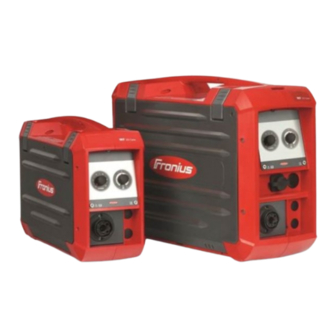
General Device concept The VR 4000 Case wire-feed unit is contai- ned in a fully sealed plastic housing. De- pending on the model, it is suitable for wirespools with the following maximum dia- meters: D200: 200 mm (7.87 in.) D300: 300 mm (11.81 in.) The standard 4-roller drive has good wire feeding properties. -
Page 20: Warning Notices On The Device
The safety symbols warn against operating the equipment incorrectly, as this may result in serious injury and damage. 40,0006,3035 VR 4000 Case 4R/G/W/F++ 4,049,025 Part No.: www.fronius.com XXXXXXXXXX Ser.No.: IEC 60 974-5/-10 Cl.A IP 23 55 V 24 V 0.5-22 m/min... -
Page 21: Crane Transport
Do not dispose of used devices with domestic waste. Dispose of them accord- ing to the safety rules. Keep hands, hair, clothing and tools away from moving parts. For example: Cogs Feed rollers Wirespools and wire electrodes Do not reach into the rotating cogs of the wire drive or into rotating drive com- ponents. -
Page 23: Control Elements And Connections
Control elements and connections... -
Page 25: Description Of The Control Panels
Description of the control panels Safety WARNING! Danger from incorrect operation. Possible serious injury and damage to property. ► Do not use the functions described here until you have read and completely under- stood these Operating Instructions. ► Do not use the functions described here until you have fully read and understood all of the Operating Instructions for the system components, in particular the safety rules! General The functions on the control panel are all arranged in a logical way. -
Page 26: Control Panel
Control panel General The control panel allows straightforward manual setting of the welding parameters. Control panel Function Welding power/wire feed speed adjuster has a different function depending on the welding process being used: MIG/MAG pulse synergic welding, MIG/MAG standard synergic wel- ding: setting the welding power MIG/MAG standard manual wel-... -
Page 27: Connections And Mechanical Components
Connections and mechanical components Overview of con- An overview of the connections available for the welding torch can be found in the spare nections for the parts list in the Appendix. welding torch VR 4000 Case Welding torch connection D200 front for connecting the welding torch Torch control connection for connecting the welding torch... -
Page 28: Vr 4000 Case Side
VR 4000 Case Wirespool holder with brake side D200: for holding standard wirespools with a max. diameter of 200 mm (7.87 in.) and max. weight of 5 kg (11.02 lb.) D300: for holding standard wirespools with a max. diameter of 300 mm (11.81 in.) and max. - Page 29 Mounting lug for securing the interconnecting hosepack Blanking covers positions for VR 4000 Case gas flow meter option Blanking cover position for VR 4000 Case current socket option Blanking cover position for VR 4000 Case external start signal option (10) Remote control connection...
-
Page 31: Installation And Commissioning
Installation and commissioning... -
Page 33: Before Commissioning
Before commissioning Safety WARNING! Operating the equipment incorrectly can cause serious injury and damage. ► Do not use the functions described here until you have read and completely under- stood these Operating Instructions. ► Do not use the functions described here until you have fully read and understood all of the Operating Instructions for the system components, in particular the safety rules. -
Page 34: Connecting Wire-Feed Unit To Power Source
Connecting wire-feed unit to power source General informa- The wire-feed unit is connected to the power source using the interconnecting hosepack. tion Connecting the WARNING! wire-feed unit to the power source Fitting the equipment incorrectly can cause serious injury and damage. Do not carry out the steps described here until you have read and completely understood all the operating instructions. -
Page 35: Connecting The Welding Torch
Connecting the welding torch Safety NOTE! When connecting the welding torch, check that ► all connections are connected properly ► all cables, leads and hosepacks are undamaged and correctly insulated. Connecting a The welding torch control plug comes MIG/MAG welding in two versions: torch as a conventional torch control... -
Page 36: Inserting/Replacing Feed Rollers
Inserting/replacing feed rollers General In order to achieve optimum wire electrode feed, the feed rollers must be suitable for the diameter and alloy of the wire being welded. IMPORTANT! Only use feed rollers that match the wire electrode. An overview of the feed rollers available and their possible areas of use can be found in the spare parts lists. -
Page 37: Inserting The Wirespool, Inserting The Basket-Type Spool
Inserting the wirespool, inserting the basket-type spool Safety CAUTION! Risk of injury from springiness of spooled wire electrode. While inserting the wirespool, hold the end of the wire electrode firmly to avoid injuries caused by the wire springing back. CAUTION! Risk of injury from falling wirespool. -
Page 38: Inserting A Basket-Type Spool: D300 Device
Inserting a bas- CAUTION! ket-type spool: D300 device Risk of injury and material damage from falling basket-type spool. Place the basket-type spool on the adapter provided in such a way that the bars on the spool are inside the adapter guideways. -
Page 39: Feeding In The Wire Electrode
Feeding in the wire electrode Feeding in the CAUTION! wire electrode Risk of injury from springiness of spooled wire electrode. When inserting the wire electrode into the 4-roller drive, hold the end of the wire electrode firmly to avoid injuries caused by the wire springing back. CAUTION! Risk of damage to the welding torch from sharp end of wire electrode. -
Page 40: Setting The Contact Pressure
If you release the "Wire threading" button and press it again before one second has elapsed, the sequence starts again from the beginning. This makes it possible to continu- ously position the wire at a low wire feed speed of 1 m/min or 39.37 ipm where necessary. If there is no "Wire threading"/"Gas-test"... - Page 41 Contact pressure U-slot rollers standard values Steel 4 - 5 CrNi 4 - 5 Tubular cored electrodes 2 -3...
-
Page 42: Adjust The Brake
Adjust the brake General CAUTION! Risk of injury and material damage from the welding current and accidental ignition of an arc. Before starting work, disconnect the ground earth connection between the welding system and the workpiece. CAUTION! Risk of injury and damage from wire electrode emerging. While working: ►... -
Page 43: Setting The Brake: D300 Device
STOP Setting the brake: D300 device STOP STOP... -
Page 44: Start-Up
Start-up Safety WARNING! Operating the equipment incorrectly can cause serious injury and damage. Do not use the functions described until you have thoroughly read and understood the fol- lowing documents: ► these operating instructions ► all the operating instructions for the system components, especially the safety rules The wire-feed unit is started by pressing the torch trigger (for manual applications) or by means of a welding start-up signal (for automatic applications). -
Page 45: Troubleshooting And Maintenance
Troubleshooting and maintenance... -
Page 47: Care, Maintenance And Disposal
Care, maintenance and disposal General Under normal operating conditions, the welding system requires only a minimum of care and maintenance. However, it is vital to observe some important points to ensure the weld- ing system remains in a usable condition for many years. Safety WARNING! Incorrect operation or shoddy workmanship can cause serious injury or damage. -
Page 48: Disposal
Disposal Dispose of in accordance with the applicable national and local regulations. -
Page 49: Technical Data
Technical data... -
Page 51: Technical Data
60 % D.C.* 100 % D.C.* 420 A 320 A Maximum shielding gas pressure 7 bar 101.53 psi Coolant Original Fronius Maximum coolant pressure 5 bar 72.49 psi Wire feed speed 0.5 - 22 m/min 19.69 - 866.14 ipm Wire drive... - Page 52 Wirespool types all standardised wirespools Maximum permitted wirespool weight 19 kg max. 41.89 lb. Wire diameter 0.8 - 1.6 mm .03 - .06 in. Wirespool diameter max. 300 mm max. 11.81 in Degree of protection IP 23 Mark of conformity S, CE, CSA Dimensions l x w x h 613 x 244 x 437 mm...
- Page 56 FRONIUS INTERNATIONAL GMBH Froniusstraße 1 A-4643 Pettenbach AUSTRIA contact@fronius.com www.fronius.com Under www.fronius.com/contact you will find the addresses of all Fronius Sales & Service Partners and locations.
Need help?
Do you have a question about the VR 4000 Case D200 and is the answer not in the manual?
Questions and answers