Table of Contents
Advertisement
Quick Links
Evaluating the ADAQ7767-1 Flexible Resistive Input, Anti-Alias, 24-Bit, 1 MSPS, μModule DAQ Solution
FEATURES
Fully featured evaluation board for the
►
On-board IEPE sensor interface
►
On-board reference and power supply circuits
►
PC software for control and data analysis of time and frequency
►
domain
System demonstration platform-compatible
►
controller board
(EVAL-SDP-CH1Z))
Optional PMOD connector
►
EVALUATION KIT CONTENTS
EV-ADAQ7767-1FMC1Z evaluation board
►
EQUIPMENT NEEDED
SDP-H1 controller board, system demonstration platform
►
DC and AC signal source (Audio Precision
►
performance signal source)
PC running Windows 7, Windows 8, or Windows 10 with USB 2.0
►
port
SOFTWARE NEEDED
Analysis | Control | Evaluation (ACE) Software
►
ADAQ7767-1 ACE plug-In
►
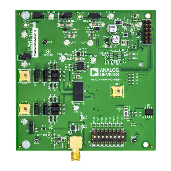
EVALUATION BOARD PHOTOGRAPH
PLEASE SEE THE LAST PAGE FOR AN IMPORTANT
WARNING AND LEGAL TERMS AND CONDITIONS.
ADAQ7767-1
(SDP-H1, high speed
®
or similar high
Figure 1. Evaluation Board Photograph
User Guide | EVAL-ADAQ7767-1
GENERAL DESCRIPTION
The EV-ADAQ7767-1FMC1Z evaluation kit enables simple evalu-
ation of the ADAQ7767-1, flexible resistive input, anti-alias, 24-
®
bit, 1 MSPS, µModule
data acquisition (DAQ) solution. The EV-
ADAQ7767-1FMC1Z is used alongside a downloadable evaluation
software to fully configure the features of the ADAQ7767-1 and
display the conversion results in the time and frequency domains.
The EV-ADAQ7767-1FMC1Z connects to the USB port of a PC via
the SDP-H1 system demonstration platform board. By default, the
3.3 V rail is supplied by the SDP-H1 and regulated by the on-board
power solution to ±15 V and +5.3 V to power the ADAQ7767-1
and its support components. An integrated electronic piezoelectric
(IEPE)-interface and a pair of input buffers are included to evaluate
the ADAQ7767-1 across a variety of input types.
For a full description of the ADAQ7767-1, see the ADAQ7767-1
data sheet, which must be consulted in conjunction with this user
guide when using the EV-ADAQ7767-1FMC1Z evaluation board.
For the current schematic, layouts, and bill of materials, see the
EVAL-ADAQ7767-1
product page.
UG-2195
Rev. 0 | 1 of 26
Advertisement
Table of Contents

Related Manuals for Analog Devices EVAL-ADAQ7767-1


Summary of Contents for Analog Devices EVAL-ADAQ7767-1
-
Page 1: Features
User Guide | EVAL-ADAQ7767-1 UG-2195 Evaluating the ADAQ7767-1 Flexible Resistive Input, Anti-Alias, 24-Bit, 1 MSPS, μModule DAQ Solution FEATURES GENERAL DESCRIPTION Fully featured evaluation board for the ADAQ7767-1 The EV-ADAQ7767-1FMC1Z evaluation kit enables simple evalu- ► ation of the ADAQ7767-1, flexible resistive input, anti-alias, 24- On-board IEPE sensor interface ►... -
Page 2: Table Of Contents
User Guide EVAL-ADAQ7767-1 TABLE OF CONTENTS Features..............1 Power Supplies..........10 Evaluation Kit Contents......... 1 Hardware Link Options........12 Equipment Needed..........1 On-Board Connectors........14 Software Needed...........1 Evaluation Board Software........15 General Description..........1 Software Installation Procedures......15 Evaluation Board Photograph........1 Evaluation Board Setup Procedures....16 Quick Start Guide.......... -
Page 3: Quick Start Guide
1. Ensure the SDP-H1 controller board is disconnected from the the Analog Devices subfolder in the Programs menu. PC, and then, install the ACE (Analysis, Control, Evaluation) 6. Double click ADAQ7767-1 Board to open the ADAQ7767-1 software to evaluate the ADAQ7767-1. Restart the PC after Board View window. -
Page 4: Example Data Capture For The Ac Signal
User Guide EVAL-ADAQ7767-1 EXAMPLE DATA CAPTURE FOR THE AC SIGNAL To capture data for the AC signal, take the following steps: 4. The sampled data is now present in the data capture tabs (ADAQ7767-1 Board Waveform, ADAQ7767-1 Board Histo- 1. Start the ACE Software software. -
Page 5: Example Data Capture For The Dc Signal
User Guide EVAL-ADAQ7767-1 EXAMPLE DATA CAPTURE FOR THE DC SIGNAL A sinc3 filter with ODR = 50 SPS is a sweet spot for measurement 5. Adjust the number of samples to be collected accordingly be- of a pure DC signal because the sinc notch appears at 50 Hz and fore Run Once is clicked. - Page 6 User Guide EVAL-ADAQ7767-1 EXAMPLE DATA CAPTURE FOR THE DC SIGNAL Figure 5. Set the Sinc3 Filter Decimation Ratio Figure 6. Histogram of Output Codes with IN2+ and IN2− Shorted to GND and Sinc3 = 50 SPS analog.com Rev. 0 | 6 of 26...
-
Page 7: How To Calculate The Sinc3_Dec_Rate
User Guide EVAL-ADAQ7767-1 EXAMPLE DATA CAPTURE FOR THE DC SIGNAL HOW TO CALCULATE THE SINC3_DEC_RATE VALUE By default, the EV-ADAQ7767-1FMC1Z provides the DUT with a MCLK of approximately 16.384 MHz. To achieve an ODR = 50 SPS using the sinc3 filter, use the... -
Page 8: Evaluation Board Hardware
User Guide EVAL-ADAQ7767-1 EVALUATION BOARD HARDWARE Figure 7 shows the simplified block diagram of the EV- ADP5076 (VR1), ADP7142 (U8), ADP7182 (U9), and LTC3526LB-2 ADAQ7767-1FMC1Z evaluation board connected to the SDP-H1 (U7). A pair of ADA4625-1 (U2 and U3) op amps can be used to controller board. -
Page 9: Analog Inputs
User Guide EVAL-ADAQ7767-1 EVALUATION BOARD HARDWARE by providing a 24 V rail at HV_VDD via the on-board supply or ANALOG INPUTS an external supply, and switches on SW_S1 and SW_S2 on the The analog inputs, AINP and AINN, are accessible either through S2 mechanical switch. -
Page 10: Power Supplies
User Guide EVAL-ADAQ7767-1 EVALUATION BOARD HARDWARE EXT_VDD and EXT_VSS. See Table 2 for the recommended power POWER SUPPLIES supply rails when using the buffers and/or the IEPE interface and The EV-ADAQ7767-1FMC1Z obtains its power from the 3.3 V rail of Table 3 for the power supply link options. - Page 11 User Guide EVAL-ADAQ7767-1 EVALUATION BOARD HARDWARE Table 2. Recommended Power Supply Rails when Using Input Buffers and/or An IEPE Interface (Continued) Buffer Supply VDD_BUF (V) IEPE Supply HV_VDD Input Range (V) ADAQ7767-1 Input Pins Positive Negative Comments IN2− to GND...
-
Page 12: Hardware Link Options
User Guide EVAL-ADAQ7767-1 EVALUATION BOARD HARDWARE ADAQ7767-1FMC1Z. Table 3 shows the default link positions for HARDWARE LINK OPTIONS the EV-ADAQ7767-1FMC1Z. Multiple link options must be set correctly for the appropriate operating setup before applying the power and signal to the EV- Table 3. - Page 13 User Guide EVAL-ADAQ7767-1 EVALUATION BOARD HARDWARE Table 3. Default Links and Link Options (Continued) Function Link Default Position Comment VDD2_ADC Supply 0 Ω at R16 The VDD2_ADC pin of the ADAQ7767-1 uses the internal LDO regulator by default. Optionally, remove R16 and connect the external supply to the VDD2_ADC turret.
-
Page 14: On-Board Connectors
User Guide EVAL-ADAQ7767-1 EVALUATION BOARD HARDWARE ON-BOARD CONNECTORS Table 4 provides information about the external on-board connectors on the EV-ADAQ7767-1FMC1Z. Table 4. On-Board Connectors Connector Function AINP/AINN SMB analog inputs for AC signals T1/T2 Turrets for DC analog inputs IEPE_IN... -
Page 15: Evaluation Board Software
EV-ADAQ7767-1FMC1Z product page. The ACE Software is a desktop software application that allows the evaluation and control of multiple evaluation systems across the Analog Devices, Inc., product portfolio. The installation process consists of the ACE Software and SDP-H1 driver installations. -
Page 16: Evaluation Board Setup Procedures
User Guide EVAL-ADAQ7767-1 EVALUATION BOARD SOFTWARE CONNECTING THE EV-ADAQ7767-1FMC1Z AND THE SDP-H1 TO A PC After installing the Software, take the following steps to set up the EV-ADAQ7767-1FMC1Z and SDP-H1: 1. Ensure that all configuration links are in the appropriate posi-... -
Page 17: Launching The Software
ADAQ7767-1 Board View (see Figure 18). 1. From the Start menu, select All Programs > Analog Devices > ACE > ACE.exe to open the main software screen (see 5. Double click the ADAQ7767-1 Board Chip icon to open the Figure 17). - Page 18 User Guide EVAL-ADAQ7767-1 EVALUATION BOARD SOFTWARE Figure 18. ADAQ7767-1 Board View Figure 19. ADAQ7767-1 Board Chip View analog.com Rev. 0 | 18 of 26...
-
Page 19: Description Of The Analysis Window
User Guide EVAL-ADAQ7767-1 EVALUATION BOARD SOFTWARE The ADAQ7767-1 Board Analysis window contains the DESCRIPTION OF THE ANALYSIS WINDOW ADAQ7767-1 Board Waveform (see Figure 21), ADAQ7767-1 Click Proceed to Analysis in the ADAQ7767-1 Board Chip View Board Histogram (see Figure 22), and ADAQ7767-1 Board FFT... - Page 20 User Guide EVAL-ADAQ7767-1 EVALUATION BOARD SOFTWARE The Single Tone Analysis and Two Tone Analysis sections set CAPTURE SETTINGS up the fundamental frequencies included in the FFT analysis. When The output data rate (ODR:) is automatically calculated by the analyzing one frequency, use the Single Tone Analysis section, software based on the selected ADC filter settings.
- Page 21 User Guide EVAL-ADAQ7767-1 EVALUATION BOARD SOFTWARE The Histogram graph displays the number of hits per code within ADAQ7767-1 Board Histogram Tab the sampled data. This graph is useful for DC analysis and indi- The ADAQ7767-1 Board Histogram tab contains the Histogram cates the noise performance of the device.
- Page 22 User Guide EVAL-ADAQ7767-1 EVALUATION BOARD SOFTWARE section displays the signal-to-noise ratio (SNR) and other noise ADAQ7767-1 Board FFT Tab performance results. The Distortion section displays the harmonic The ADAQ7767-1 Board FFT tab displays FFT information for the content of the sampled signal, and the DC section displays the DC...
-
Page 23: Exiting The Software
User Guide EVAL-ADAQ7767-1 EVALUATION BOARD SOFTWARE EXITING THE SOFTWARE Input Range Configuration To exit the software, go to File in the upper right tab and then click To select the input range, take the following steps: Close ACE. 1. Configure the P1 and P2 jumpers on the EV- CONFIGURING THE EV-ADAQ7767-1FMC1Z ADAQ7767-1FMC1Z to either IN1+ and IN1−, IN2+ and IN2−,... - Page 24 User Guide EVAL-ADAQ7767-1 EVALUATION BOARD SOFTWARE The following are the core ADC settings configurable in ADC Configuration ADAQ7767-1 Board Chip View: Apart from the input range, other settings configurable from the LINEARITY BOOST BUFFERS ADAQ7767-1 Board Chip View pertain to the core ADC settings ►...
-
Page 25: Example Data Capture
User Guide EVAL-ADAQ7767-1 EVALUATION BOARD SOFTWARE Reset Switches Press the S1 switch to reset the DUT. Resetting the DUT resets all register settings to their default values. A reset switch is also available on the SDP-H1 to reset the control- ler board. - Page 26 Evaluation Board until you have read and agreed to the Agreement. Your use of the Evaluation Board shall signify your acceptance of the Agreement. This Agreement is made by and between you (“Customer”) and Analog Devices, Inc. (“ADI”), with its principal place of business at Subject to the terms and conditions of the Agreement, ADI hereby grants to Customer a free, limited, personal, temporary, non-exclusive, non-sublicensable, non-transferable license to use the Evaluation Board FOR EVALUATION PURPOSES ONLY.
Need help?
Do you have a question about the EVAL-ADAQ7767-1 and is the answer not in the manual?
Questions and answers