Table of Contents
Advertisement
Quick Links
One Technology Way • P.O. Box 9106 • Norwood, MA 02062-9106, U.S.A. • Tel: 781.329.4700 • Fax: 781.461.3113 • www.analog.com
Evaluating the
FEATURES
Fully featured Pmod evaluation board with a Pmod to
FMC interposer board
Versatile analog signal conditioning circuitry
On-board reference and ADC drivers
PC software for control and data analysis of time and
frequency domain
System demonstration platform compatible (EVAL-SDP-CH1Z)
EVALUATION BOARD KIT CONTENTS
EV-ADAQ4003PMDZ
Pmod evaluation board
EVAL-PMD-IB1Z
Pmod to FMC interposer board
EQUIPMENT NEEDED
PC running Windows® 10 or higher
EVAL-SDP-CH1Z (SDP-H1) controller board
Precision signal source
Cable (SMB input to evaluation board)
Standard USB A to Mini-B USB cable
Band-pass filter suitable for 18-bit testing (value based on
signal frequency)
SOFTWARE NEEDED
ADAQ400x evaluation software
PLEASE SEE THE LAST PAGE FOR AN IMPORTANT
WARNING AND LEGAL TERMS AND CONDITIONS.
EVAL-ADAQ4003FMCZ
ADAQ4003
18-Bit, 2 MSPS, µModule Data Acquisition Solution
Evaluation Board User Guide
GENERAL DESCRIPTION
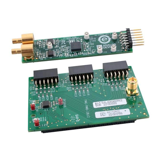
The ADAQ4003 µModule® data acquisition system evaluation kit
(EVAL-ADAQ4003FMCZ) contains the EV-ADAQ4003PMDZ
peripheral module (Pmod) board and the EVAL-PMD-IB1Z
Pmod to field programmable grid array (FPGA) mezzanine
card (FMC) interposer board that interfaces with the system
demonstration controller board (EVAL-SDP-CH1Z) via a 160-pin
FMC connector as shown in Figure 1.
The ADAQ4003 µModule combines multiple common signal
processing and conditioning blocks into a single device that
includes a low noise, fully differential analog-to-digital converter
(ADC) driver, a stable reference buffer, a high resolution, 18-bit,
2 MSPS successive approximation register (SAR) ADC, and the
critical passive components necessary for optimum performance.
The EV-ADAQ4003PMDZ on-board components include the
following:
•
The
ADR4550
voltage reference (see Figure 33)
•
An optional
low distortion, unity-gain stable, high speed op amp
(see Figure 34)
•
An optional
Figure 34)
•
The
LT5400-4
Note that J1 and J2 on the EV-ADAQ4003PMDZ provide low
noise analog signal sources.
For full details on the ADAQ4003, see the ADAQ4003 data
sheet, which must be consulted in conjunction with this user
guide when using the EVAL-ADAQ4003FMCZ.
Rev. 0 | Page 1 of 31
high precision, buffered band gap, 5.0 V
ADA4898-1
high voltage, low noise,
AD8251
programmable gain in-amp (see
quad matched, low drift, resistor network.
UG-1533
Advertisement
Table of Contents

Related Manuals for Analog Devices EVAL-ADAQ4003FMCZ


Summary of Contents for Analog Devices EVAL-ADAQ4003FMCZ
-
Page 1: Features
For full details on the ADAQ4003, see the ADAQ4003 data sheet, which must be consulted in conjunction with this user guide when using the EVAL-ADAQ4003FMCZ. PLEASE SEE THE LAST PAGE FOR AN IMPORTANT Rev. 0 | Page 1 of 31... -
Page 2: Table Of Contents
EVAL-ADAQ4003FMCZ Evaluation Board Kit Photograph ..3 Summary Tab ................18 Evaluation Board Hardware ............4 Troubleshooting ................19 Setting Up the EVAL-ADAQ4003FMCZ Evaluation Kit ..4 ADAQ400x Evaluation Board Software Troubleshooting ..19 EVAL-SDP-CH1Z (SDP-H1) Board .......... 4 Hardware Throubleshooting ............ 19 Power Supplies ................ -
Page 3: Eval-Adaq4003Fmcz Evaluation Board Kit Photograph
EVAL-ADAQ4003FMCZ Evaluation Board User Guide UG-1533 EVAL-ADAQ4003FMCZ EVALUATION BOARD KIT PHOTOGRAPH EV-ADAQ4003PMDZ EVAL-SDP-CH1Z EVAL-PMD-IB1Z Figure 1. Rev. 0 | Page 3 of 31... -
Page 4: Evaluation Board Hardware
UG-1533 EVAL-ADAQ4003FMCZ Evaluation Board User Guide EVALUATION BOARD HARDWARE SETTING UP THE EVAL-ADAQ4003FMCZ (SDP-H1) to capture the data via a graphic user interface (GUI) (see Figure 1). The SDP-H1 requires power from a 12 V wall EVALUATION KIT adapter. The SDP-H1 has a Xilinx® Spartan®-6 and an... -
Page 5: Power Supplies
EVAL-ADAQ4003FMCZ Evaluation Board User Guide UG-1533 POWER SUPPLIES Take the following steps to set up the EV-ADAQ4003PMDZ when using a benchtop power supply of ±15.5 V: The system demonstration platform board (SDP-H1) supplies Connect the EV-ADAQ4003PMDZ board to EVAL-PMD- 3.3 V to power the rails for the different components on the IB1Z interposer board at the P1 header (see Figure 1). -
Page 6: Analog Inputs
UG-1533 EVAL-ADAQ4003FMCZ Evaluation Board User Guide ANALOG INPUTS The analog inputs are fully differential by default. If a single-ended bipolar input is desired, such as ±10 V, the EV-ADAQ4003PMDZ The analog inputs of the EV-ADAQ4003PMDZ, J1 and J2, are can be configured for single-ended to differential conversion Subminiature Version B (SMB) connectors. -
Page 7: Link Configuration For Different Gain Options
EVAL-ADAQ4003FMCZ Evaluation Board User Guide UG-1533 LINK CONFIGURATION FOR DIFFERENT GAIN OPTIONS Multiple link options must be set correctly for appropriate gain configuration of the ADAQ4003. Table 3 details the different gain positions for the links of the EV-ADAQ4003PMDZ. Figure 6. Gain = 1 Figure 4. -
Page 8: Evaluation Board Software
UG-1533 EVAL-ADAQ4003FMCZ Evaluation Board User Guide EVALUATION BOARD SOFTWARE INSTALLING THE SOFTWARE To install the software required to evaluate the ADAQ4003PMDZ, take the following steps: Download the ADAQ400x evaluation board software. Double-click the setup.exe file to open the software installation window (see Figure 8). - Page 9 EVAL-ADAQ4003FMCZ Evaluation Board User Guide UG-1533 Click Next>> to complete the installation and to launch the SDP-H1 driver installation (see Figure 13 and Figure 14). These drivers must be installed for the evaluation board to function correctly. Figure 16. ADI SDP Drivers 2.4.0.268 Setup License Agreement 10.
-
Page 10: Ev-Adaq4003Pmdz Operation And Connection Sequence
EV-ADAQ4003PMDZ are connected correctly by going to the Device Manager on the PC. Analog Devices System Development Platform (32MB) should appear under the ADI Development Tools dropdown list (see Figure 20). Figure 21. SDP-H1 Board Not Detected... -
Page 11: Software Operation
EVAL-ADAQ4003FMCZ Evaluation Board User Guide UG-1533 SOFTWARE OPERATION When the ADAQ400x evaluation board software detects the generic attached to the PC, the window in Figure 24 opens. Figure 24. Setup Screen DESCRIPTION OF THE USER PANEL The following describes the user panel shown in Figure 24. - Page 12 The Help menu (Label 1 in Figure 24) offers information about the enters a value larger than the ability of the existing device, the software reverts to the maximum throughput. • Analog Devices Website The Voltage Reference dropdown menu is Label 5 in Figure 24. By • User Guide...
- Page 13 EVAL-ADAQ4003FMCZ Evaluation Board User Guide UG-1533 Click Enable Status Bits to enable the content of the status header Within any of the chart panels, the tools shown in Table 4 allow the user to control the different chart displays. (see Label 9 in Figure 24). Status bits can be clocked out at the end of the conversion data using six extra clocks when enabled.
-
Page 14: Waveform Capture
UG-1533 EVAL-ADAQ4003FMCZ Evaluation Board User Guide WAVEFORM CAPTURE Figure 28 shows the waveform capture. The input signal is a 1 kHz sine wave. The waveform analysis reports the amplitudes recorded from the captured signal in addition to the frequency of the signal tone. -
Page 15: Histogram
EVAL-ADAQ4003FMCZ Evaluation Board User Guide UG-1533 HISTOGRAM DC Testing More commonly, the histogram is used for dc testing where AC Testing the user tests the µModule for the code distribution for dc input, The ac testing histogram tests the µModule for the code... -
Page 16: Fft Capture
UG-1533 EVAL-ADAQ4003FMCZ Evaluation Board User Guide FFT CAPTURE more than a few volts peak-to-peak, use the on-board amplifiers to amplify the signal, thus preventing the filter from distorting the The traditional ac characteristics of the converter can be input signal. -
Page 17: Inl_Dnl Capture Linearity Testing
EVAL-ADAQ4003FMCZ Evaluation Board User Guide UG-1533 INL_DNL CAPTURE LINEARITY TESTING In an ideal ADC, code transitions are 1 LSB apart. DNL is the maximum deviation from this ideal value. DNL is often specified in The INL_DNL tab displays linearity analysis (see Figure 31). -
Page 18: Summary Tab
UG-1533 EVAL-ADAQ4003FMCZ Evaluation Board User Guide SUMMARY TAB The Summary tab captures the window information and displays the captured information in one panel with a synopsis of the information including key performance parameters, such as SNR and THD. Figure 32. Summary Tab, Shows All Captured Windows... -
Page 19: Troubleshooting
To troubleshoot the ADAQ400x evaluation board software, take Check that the power is applied within the power ranges the following steps: described in the Setting Up the EVAL-ADAQ4003FMCZ Evaluation Kit section. Install the software before connecting the hardware to the PC. -
Page 20: Evaluation Board Schematics And Silkscreens
UG-1533 EVAL-ADAQ4003FMCZ Evaluation Board User Guide EVALUATION BOARD SCHEMATICS AND SILKSCREENS EV-ADAQ4003PMDZ VOLTAGE REFERENCE P5P5V 0Ω TBD0603 TBD0603 VOUT VREF 2.2µF 0.1µF 0Ω 0Ω ADR4550BRZ 0.1µF 2.2µF TBD0603 LT3032IDE#PBF P15P5V P15V OUTP P15V P15V P5P5V ADJP/NC OUT1 0Ω 0Ω 698kΩ... - Page 21 EVAL-ADAQ4003FMCZ Evaluation Board User Guide UG-1533 TBD0603 0.1µF AGND OPAMP_INV1 OPAMP_OUT1 TBD0402 0Ω NINV 0Ω –V TBD0603 ADA4898-1YRDZ 0Ω INAMP_INN OUTP R1KN 3PIN_JUMPER TBD0603 AGND R1K1N 0.1µF 131-3701-301 AGND JUMPER4_0402 3PIN_JUMPER AGND TBD0603 AGND AGND R1KP OUTN R1K1P PLACE TBD0402 RESISTORS UNDER THE LT5400 PACKAGE 0.1µF...
- Page 22 UG-1533 EVAL-ADAQ4003FMCZ Evaluation Board User Guide Figure 35. EV-ADAQ4003PMDZ Silkscreen, Top Layer Figure 36. EV-ADAQ4003PMDZ, Layer 1 Figure 37. EV-ADAQ4003PMDZ, Layer 2 Rev. 0 | Page 22 of 31...
- Page 23 EVAL-ADAQ4003FMCZ Evaluation Board User Guide UG-1533 Figure 38. EV-ADAQ4003PMDZ, Layer 3 GND Figure 39. EV-ADAQ4003PMDZ, Layer 4 Secondary Rev. 0 | Page 23 of 31...
-
Page 24: Eval-Pmd-Ib1Z
UG-1533 EVAL-ADAQ4003FMCZ Evaluation Board User Guide EVAL-PMD-IB1Z TBD0603 TBD0603 TBD0603 TBD0603 0Ω 0Ω 0Ω 0Ω LA04_N 0Ω LA04_P LA11_N LA08_N LA06_P 0Ω LA06_N 0Ω LA02_N 0Ω 0Ω LA03_N LA07_N 0Ω LA11_P 0Ω 0Ω LA10_N LA10_P 0Ω 0Ω 0Ω 0Ω 0Ω... - Page 25 EVAL-ADAQ4003FMCZ Evaluation Board User Guide UG-1533 Figure 41. EVAL-PMD-IB1Z, Top Layer Rev. 0 | Page 25 of 31...
- Page 26 UG-1533 EVAL-ADAQ4003FMCZ Evaluation Board User Guide Figure 42. EVAL-PMD-IB1Z Silkscreen, Primary Rev. 0 | Page 26 of 31...
- Page 27 EVAL-ADAQ4003FMCZ Evaluation Board User Guide UG-1533 Figure 43. EVAL-PMD-IB1Z Silkscreen, Secondary Rev. 0 | Page 27 of 31...
- Page 28 UG-1533 EVAL-ADAQ4003FMCZ Evaluation Board User Guide Figure 44. EVAL-PMD-IB1Z, Secondary Rev. 0 | Page 28 of 31...
-
Page 29: Ordering Information
EVAL-ADAQ4003FMCZ Evaluation Board User Guide UG-1533 ORDERING INFORMATION BILL OF MATERIALS Table 5. EV-ADAQ4003PMDZ Bill of Materials Reference Designator Description Manufacturing Part No. +15.5V, −15.5V, −VS, GND, VIN Connector printed circuit board Components Corporation TP-104-01-09 (PCB) test points, white C1, C7 22 µF ceramic capacitors, X5R,... - Page 30 95.3 kΩ resistor, precision thick Panasonic ERJ-2RKF9532X film chip 3.3 kΩ resistor, precision thick Panasonic ERJ-2RKF3301X film chip Resistor network quad matched Analog Devices, Inc. LT5400BHMS8E-4#PBF Ultralow noise, high accuracy, Analog Devices ADR4550BRZ 5.0 V voltage reference Dual positive and negative Analog Devices LT3032IDE#PBF low noise LDO regulator 1 A/0.6 A, dc-to-dc switching...
- Page 31 By using the evaluation board discussed herein (together with any tools, components documentation or support materials, the “Evaluation Board”), you are agreeing to be bound by the terms and conditions set forth below (“Agreement”) unless you have purchased the Evaluation Board, in which case the Analog Devices Standard Terms and Conditions of Sale shall govern. Do not use the Evaluation Board until you have read and agreed to the Agreement.
Need help?
Do you have a question about the EVAL-ADAQ4003FMCZ and is the answer not in the manual?
Questions and answers