Fluidwell F Series Manual
Batch controller two-stage control and pulse output
Hide thumbs
Also See for F Series:
- Manual (64 pages) ,
- User manual (60 pages) ,
- Operation manual (60 pages)
Table of Contents
Advertisement
Quick Links
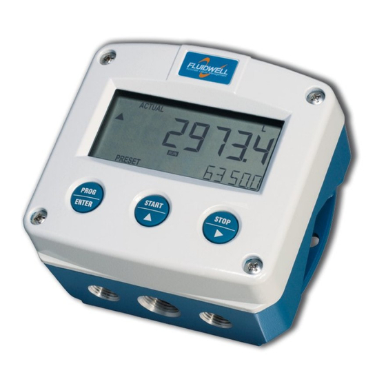
F130-P
BATCH CONTROLLER
two-stage control and pulse output
Signal input flowmeter: pulse, Namur and coil
External controls: start and stop
Digital outputs: two control outputs for two stage control, or
one control output and pulse output
Options: Intrinsically safe, Modbus communication
F-Series - Field mounted indicators for safe and hazardous areas.
More info: www.fluidwell.com/fseries
Advertisement
Table of Contents


Need help?
Do you have a question about the F Series and is the answer not in the manual?
Questions and answers