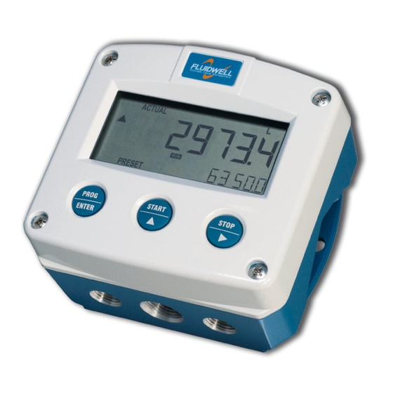
Fluidwell F Series User Manual

Flow rate indicator / totalizer, signal input: pulse, namur or coil flowmeter signal, options: intrinsically safe backlight
Hide thumbs Also See for F Series:
Table of Contents

Advertisement

Quick Links

User Manual
F012-P
FLOW RATE INDICATOR / TOTALIZER
Signal input:
pulse, NAMUR or coil flowmeter signal
Options:
intrinsically safe
backlight
F-Series - Field mounted indicators for safe and hazardous areas
More info: www.fluidwell.com/fseries

Advertisement

Table of Contents
loading

Summary of Contents for Fluidwell F Series

  • Page 1 User Manual F012-P FLOW RATE INDICATOR / TOTALIZER Signal input: pulse, NAMUR or coil flowmeter signal Options: intrinsically safe backlight F-Series - Field mounted indicators for safe and hazardous areas More info: www.fluidwell.com/fseries...
  • Page 2: Table Of Contents

    User Manual F012-P TABLE OF CONTENTS ABOUT THIS MANUAL......................How to use this manual ....................Use of pictograms ......................Warranty and technical support ..................Model Reference ......................SAFETY ............................ Personal safety ....................... End-user responsibilities....................Potential equipment damage ..................Disposal of electronic waste ................... INTRODUCTION........................
  • Page 3 F012-P User Manual Terminal connectors safe area applications - Type PF, PM ........... 32 6.6.1 Terminals GND-1-2: Power supply ................. 32 6.6.2 Terminals 5-7: flowmeter input ..................33 INTRINSICALLY SAFE APPLICATIONS ................36 Identification........................36 Electrical installation in hazardous areas................ 37 7.2.1 Installations based on FM or CSA Certificate ..............
  • Page 4: About This Manual

    ● incorrect functioning of the unit or connected instruments. A note informs you of important information. WARRANTY AND TECHNICAL SUPPORT For warranty and technical support on your Fluidwell products, visit our internet site www.fluidwell.com or contact us at support@fluidwell.com. MODEL REFERENCE Hardware version: 03.03.xx...
  • Page 5: Safety

    F012-P User Manual SAFETY PERSONAL SAFETY ● Explosion hazard: Never open the unit when explosive atmosphere is present, and the unit is connected to a power supply or consuming device like the internal battery supply. ● Risk of electric shock: Only open the unit if all leads are free of potential electrical energy. ●...
  • Page 6: Introduction

    User Manual F012-P INTRODUCTION SYSTEM DESCRIPTION The flow rate indicator / totalizer model F012-P is a microprocessor-driven instrument designed to show the current flow rate, resettable total and non-resettable accumulated total. Fig. 1: The F012 This manual describes the daily use, configuration and installation of the F012-P with pulse input from a flowmeter and its available options.
  • Page 7: Installation Example

    F012-P User Manual Options ● Intrinsic safety (Type XI) ● Power and sensor supply (Types PB, PC, PD, PF, PM, PX, in various combinations) ● Panel mount enclosure (Types HB, HC) ● Flame-proof enclosure (Type XF) ● Display backlight (Type ZB). INSTALLATION EXAMPLE Following parts can be recognized in below installation example.
  • Page 8: Operation

    User Manual F012-P OPERATION This unit may only be operated by authorized and trained personnel who have read and understood this manual, particularly Section 2: Safety [»5] INTRODUCTION This chapter describes the daily use and operation of the F012-P. For this, the F-Series is equipped with a control panel that provides the operator with various functions, information and operating modes.
  • Page 9: Backlight (Type Zb)

    F012-P User Manual Normally, the display is updated depending on the refresh rate selected in the configuration settings. By pressing any key, the display switches to refreshing the information 8 times per second. After 30 seconds of key inactivity, the display returns to the configured refresh rate. TOTAL RATE Fig. 4:...
  • Page 10: Internal Error

    User Manual F012-P 4.4.2 INTERNAL ERROR When an internal error occurs, “ALARM” will be displayed. Press the SELECT key several times to display the 4-digit error code. Consult for more information. Section B: Troubleshooting [»51] Page 10 FW_F012-P_M_v0501-03_EN...
  • Page 11: Configuration

    F012-P User Manual CONFIGURATION INTRODUCTION This chapter describes how technicians can use configuration settings to configure the F-Series for optimal functionality. Configuration of the F012-P can be done in SETUP mode, using the front keys. CONFIGURING USING SETUP MODE For an overview of Operating modes, see Section 4.1.1: Operating modes [»8] Changing settings may influence current operation In SETUP mode the unit remains fully operational.
  • Page 12: Changing Configuration Settings

    User Manual F012-P 5.2.3 CHANGING CONFIGURATION SETTINGS A menu item either contains a value (a number with optionally a decimal point and sign, e.g. -123.45) or a selection list (e.g. L – m - USGAL). After a menu item is selected in the SETUP menu, a new value can be programmed by performing the following steps.
  • Page 13: Setup Menu Overview

    F012-P User Manual SETUP MENU OVERVIEW TOTAL DEFAULT UNIT L - m3 - kg - lb - GAL - USGAL - bbl - no unit DECIMALS 0 - 3 0.000010 - 9,999,999 K-FACTOR DECIMALS K-FACTOR 0 - 6 FLOW RATE DEFAULT UNIT mL - L - m3 - mg - g - kg - ton - GAL - bbl - lb - cf - REV -...
  • Page 14: Menu 2: Flow Rate

    User Manual F012-P When a different unit is selected, the displayed values are NOT recalculated. TOTAL UNIT Determines the measurement unit for total and accumulated total. The following units can be selected: L - m3 - kg - lb - GAL - USGAL - bbl - no unit Changing the measurement unit will have consequences for operator and setup values.
  • Page 15: Menu 3: Display

    F012-P User Manual FLOW RATE UNIT Determines the measurement unit for the flow rate. The following can be selected: mL - L - m3 - mg - g - kg - ton - GAL - bbl - lb - cf - REV - no unit - scf - Nm3 - NL - P Changing the measurement unit will have consequences for operator and setup values.
  • Page 16: Menu 4: Power Management

    User Manual F012-P 5.4.4 MENU 4: POWER MANAGEMENT POWER MANAGEMENT LCD UPDATE Sets the LCD display refresh rate. The following can be selected: fast - 1 sec - 3 sec - 15 sec - 30 sec - off When a key is pressed, the display refresh rate will switch to ‘fast’ for 30 seconds.
  • Page 17: Menu 6: Others

    F012-P User Manual 5.4.6 MENU 6: OTHERS OTHERS TYPE / MODEL Provides important information on your product. This information may be SOFTWARE VERSION required for maintenance or support. SERIAL NUMBER PASS CODE All SETUP values can be password protected. A four-digit password can be programmed, for example 1234. To disable password protection, enter four zeros (0000).
  • Page 18: Installation

    User Manual F012-P INSTALLATION ● Mounting, electrical installation, start-up and maintenance of this instrument may only be carried out by trained personnel authorized by the operator of the facility. Personnel must read and understand this Operating Manual before carrying out its instructions. ●...
  • Page 19: Handling The F012-P Enclosure

    F012-P User Manual HANDLING THE F012-P ENCLOSURE 6.2.1 IDENTIFICATION The F-Series can be supplied as suitable for Safe Area or Hazardous Area. Suitability for Intrinsic Safety is indicated in the model Type XI. Refer to for identification and installation labels Section 7: Intrinsically safe applications [»36] for Intrinsically Safe applications.
  • Page 20: Opening, Assembling And Closing The F-Series

    User Manual F012-P Fig. 9: Example of F0-Series installation label (Safe Area - Type PM or PF) Serial number and year of production The serial number can be reviewed on the identification label, the installation label, or in . The production SETUP 6.3: OTHERS >...
  • Page 21 F012-P User Manual Closing / replacing the cover 1. Re-insert all terminals to their original position. 2. Carefully position the front cover onto the back cover, making sure that the gasket falls nicely into the gutter of the back cover. 3.
  • Page 22: Mechanical Installation

    User Manual F012-P MECHANICAL INSTALLATION 6.3.1 MECHANICAL DIMENSIONS Aluminum and stainless steel enclosures Note: _B_ type enclosure (extended back) not available under CSA or FM certification for intrinsically safe installation 75 mm (2.95") 90 mm (3.54") 130 mm (5.12") 112 mm (4.40") 12mm 12mm 30 mm 30 mm 30mm 30mm...
  • Page 23 F012-P User Manual Non-metallic enclosures 75 mm (2.95") 130 mm (5.12") 112 mm (4.40") HK back box: (flat bottom) 75 mm (2.95") 118 mm (4.65”) 25mm 25mm D=20mm D=20mm 12mm 12mm 30mm 30mm 24mm 24mm D=12mm D=16mm D=16mm D=20mm 36mm 36mm 0.12”...
  • Page 24: Mounting The F-Series

    User Manual F012-P 6.3.2 MOUNTING THE F-SERIES The enclosure can be installed by itself or with the aid of a mounting plate in the configurations shown below. When the product is installed on a wall or onto a meter, please use components and installation techniques that are suitable for the used materials.
  • Page 25: Electrical Installation

    F012-P User Manual ELECTRICAL INSTALLATION Hazardous area installations The following chapter gives general information regarding the electrical installation of the F012-P. gives additional specific information Section 7: Intrinsically safe applications [»36] regarding intrinsically safe installation and has priority over the information given in this chapter.
  • Page 26: Field Wiring Connections

    User Manual F012-P Connecting Protective Earth to a non-metallic enclosure When the F012-P is supplied with a non-metal enclosure (e.g. plastic), the field mount enclosure meets the requirements of class 2 (double insulated). Therefore any incoming PE conductor can be terminated with an insulating end cap.
  • Page 27: Power Supply

    F012-P User Manual All field wiring enters the F012-P through the bottom of the enclosure and connects to the circuit assembly inside the enclosure. Wiring is routed through cable glands. Please make sure to order the F012-P with the correct drilling pattern and thread (metal) or hole (plastic) sizes. The wire screens (shield) are meant to prevent electromagnetic interference and shall be terminated at one side to prevent ground loops.
  • Page 28: Terminal Connectors Safe Area Applications - Type Px, Pd

    User Manual F012-P Fig. 14: Jumper positions sensor supply voltage selection (Type PF or PM) Jumper setting External sensor supply voltage 1.2 / 3.2V DC 8.2V DC 12V DC 24V DC TERMINAL CONNECTORS SAFE AREA APPLICATIONS - TYPE PX, PD Hazardous area installations The following chapter gives general information regarding the electrical installation of the F012-P.
  • Page 29 F012-P User Manual ● COIL LO: sensitivity from about 90mV p-p ● COIL HI: sensitivity from about 20mV p-p With Type ZF or ZG still higher sensitivities are available: ● Type ZF: COIL HI sensitivity from about 10mV p-p ● Type ZG: COIL HI sensitivity from about 5mV p-p. Vref 1.2 V DC 3 Coil 2 Coil...
  • Page 30 User Manual F012-P With Type PD a sensor supply voltage of 8.1V DC can be taken from terminal 6. 6 Type PD: 8.1 V DC 3 +3.2 V DC Selectable low-pass filter 2 Signal Resistance value: 1 Shield see signal selection table Common ground unit Fig. 18: Terminals 1 - 3 (6): PNP signal input...
  • Page 31: Terminals 4-5: Power Supply - Type Px And Pd

    F012-P User Manual NAMUR signal The F012-P is suitable for use with flowmeters with NAMUR signal. The F012-P with Type PD can offer a sensor supply voltage of 8.2V at terminal 6. 6 Type PD sensor supply +8.1 V DC NAMUR 2 Signal Shield...
  • Page 32: Terminal Connectors Safe Area Applications - Type Pf, Pm

    User Manual F012-P TERMINAL CONNECTORS SAFE AREA APPLICATIONS - TYPE PF, PM Hazardous area installations This chapter applies to electrical installation of the F012-P with Type PM or PF. These Types are not fit for use in Hazardous Areas! gives specific information regarding intrinsically Section 7: Intrinsically safe applications [»36] safe installation.
  • Page 33: Terminals 5-7: Flowmeter Input

    F012-P User Manual 6.6.2 TERMINALS 5-7: FLOWMETER INPUT Three basic types of flowmeter signals can be connected to the F012-P: pulse, active pulse or coil. The screen of the signal wire can be connected to the common ground terminal (see Section 6.4.3: Field wiring connections [»26] The input signal type has to be selected with the correct SETUP-function (...
  • Page 34 User Manual F012-P A sensor supply voltage can be taken from terminal 7. 7 Sensor supply Selectable low-pass filter 6 Signal Shield Resistance value: 5 GND see signal selection table Common ground unit Fig. 27: Terminals 5 -7: PNP signal input Active signal The F012-P is suitable for flowmeters with an Active signal output.
  • Page 35 F012-P User Manual NAMUR signal The F012-P is suitable for use with flowmeters with NAMUR signal. Terminal 7 provides a selectable sensor supply ( Section 6.4.5: Sensor supply [»27] 7 Sensor supply NAMUR 6 Signal Shield 820 Ω 5 GND Common ground unit Fig. 30: Terminals 5 -7: Namur signal FW_F012-P_M_v0501-03_EN...
  • Page 36: Intrinsically Safe Applications

    User Manual F012-P INTRINSICALLY SAFE APPLICATIONS IDENTIFICATION The F012-P can be supplied as suitable for Safe Area or Hazardous Area. Suitability for Intrinsic Safety is indicated in the model Type XI. If Type XI is not indicated your unit is not suitable for Intrinsically Safe applications! Identification label To identify your F0-Series device, all field mount enclosures have a waterproof identification label placed on the outside of the product.
  • Page 37: Electrical Installation In Hazardous Areas

    F012-P User Manual ELECTRICAL INSTALLATION IN HAZARDOUS AREAS ● shows general information regarding the electrical Section 6.4: Electrical installation [»25] installation of your F012-P. The following sections give additional specific information regarding Intrinsically Safe installation, and overrules information given in other sections. ●...
  • Page 38: Electrical Data - Control Drawing

    User Manual F012-P 7.2.2 ELECTRICAL DATA - CONTROL DRAWING trol Dr ing F -P-XI Ce t r ific t a ion F0-SERIES – Type -XI T RMINAL CONNE CTORS F0 ERIE c mm on ground Ce tif r ica e number: CSA.08.2059461 Intr ins call S y afe for Class I/II/III, Division 1...
  • Page 39: Installations Based On Atex Or Iecex Certificate

    F012-P User Manual 7.2.3 INSTALLATIONS BASED ON ATEX OR IECEX CERTIFICATE Installation instructions ● For installation under ATEX directive: this Intrinsically Safe device must be installed in accordance with ATEX directive 2014/34/EU and product certificate KEMA 05ATEX1168 X. ● For installation under IECEx scheme: this Intrinsically Safe device must be installed in accordance with product certificate IECEx KEM 08.0006X.
  • Page 40: Electrical Data - Annex 1

    User Manual F012-P 7.2.4 ELECTRICAL DATA - ANNEX 1 Annex 1 ( mo el p s eci fic) to prod uct certif c i ates KEMA 0 ATEX1168 X, IECEx 00 6 Model F0..-P-XI Int nal supply for use w ith he cert ified replaceable battery type FW -Li A...
  • Page 41: Power Supply

    F012-P User Manual 7.2.5 POWER SUPPLY The F012-P can be powered from an external power supply. For Types PX or PD, an optional internal power supply is also available in the form of an intrinsically safe lithium primary battery (Type PC). When both external and internal power supplies are available, the internal power supply is interrupted and will serve as a backup supply.
  • Page 42: Configuration Examples Intrinsically Safe Applications

    User Manual F012-P Optional battery – Type PC With Type PC your product is equipped with an intrinsically safe, certified long-life Lithium primary battery. The battery will power the F012 when external power is not available, and may be exchanged in hazardous areas. For further information please see Section 8.3: Battery replacement [»46] All electrical connections made to the terminals of the intrinsically safe product (Type XI) must follow...
  • Page 43: F012-P-Px-Xi-(Zb) - Ex Ia Iic/Iiic

    F012-P User Manual 7.4.2 F012-P-PX-XI-(ZB) - EX IA IIC/IIIC Fig. 35: F012-P-PX-XI-(ZB) - Ex ia IIC/IIIC - Intrinsically Safe application Sensor supply voltage on Terminal 3: 1.2-3.2V DC. Please note: Type PX may be used in combination with the battery (Type PC). PX will power the F012-P, the battery will be disabled automatically until the power is disconnected 7.4.3 F012-P-PX-XI-ZB - EX IA IIC/IIIC...
  • Page 44: F012-P-Pd-Xi-Zb - Ex Ia Iic/Iiic

    User Manual F012-P 7.4.4 F012-P-PD-XI-ZB - EX IA IIC/IIIC Fig. 37: F012-P-PD-XI-ZB - Ex ia IIC/IIIC - Intrinsically Safe application Sensor supply voltage on Terminal 3: 1.2-3.2 V DC, Terminal 6: 8.2 V DC. Please note: Type PD may be used in combination with the battery (Type PC). PD will power the F012-P, the battery will be disabled automatically until the power is disconnected Page 44 FW_F012-P_M_v0501-03_EN...
  • Page 45: Maintenance

    F012-P User Manual MAINTENANCE GENERAL DIRECTIONS ● Mounting, electrical installation, start-up and maintenance of this instrument may only be carried out by trained personnel authorized by the operator of the facility. Personnel must read and understand this Operating Manual before carrying out its instructions. ●...
  • Page 46: Battery Replacement

    Voltaweg 23, Veghel, the Netherlands - Part. no. / Référence: FW-LiBAT-021 Primary Lithium Battery - Only replace with Fluidwell I.S. battery pack! Pile primaire au lithium - Remplacer uniquement par une pile Fluidwell à Sécurité Intrinsèque! Fig. 39: Marking battery type PC: Intrinsically Safe FWLiBAT-021 (SPC02)
  • Page 47: Battery Replacement Procedure

    F012-P User Manual 8.3.2 BATTERY REPLACEMENT PROCEDURE Before starting the battery replacement procedure, make sure that the marking on the new battery corresponds with the type of installation, as shown in Section 8.3.1: Safety instructions [»46] When used in Intrinsically Safe applications - Type PC: The hook-and-loop fastener that holds the battery is antistatic and thus fit for Hazardous Area use.
  • Page 48: Appendix A - Technical Specification

    User Manual F012-P APPENDIX A - TECHNICAL SPECIFICATION GENERAL DISPLAY Type High intensity reflective numeric and alphanumeric LCD, UV-resistant Digits 7 with height 17mm (0.67”) and 11 with height 8mm (0.31”). Various symbols and measuring units. Dimensions 90 x 40 mm (3.5” x 1.6”) Refresh rate User definable: fast - 1 sec - 3 sec - 15 sec - 30 sec - off Type ZB (option)
  • Page 49 F012-P User Manual OPERATING TEMPERATURE Safe area -40 °C to +80 °C, -40 °F to +176 °F Intrinsically safe -40 °C to +70 °C, -40 °F to +158 °F For EPL Da -40 °C to +50 °C, -40 °F to +122 °F POWER REQUIREMENTS Type PB SAFE AREA ONLY - Standard lithium primary battery.
  • Page 50: Input

    User Manual F012-P HAZARDOUS AREA (TYPE XI OR XF) Intrinsically safe ATEX appr. KEMA 05ATEX1168 X IECEx appr. IECEx KEM 08.0006X Type XI II 1 G Ex ia IIC T4 Ga Ex ia IIC T4 Ga II 1 D Ex ia IIIC T 100ºC Da Ex ia IIIC T 100ºC Da...
  • Page 51: Appendix B - Troubleshooting

    F012-P User Manual APPENDIX B - TROUBLESHOOTING Table 1 lists and describes how to troubleshoot problems that can occur when installing or operating the F012-P. Table 2 lists internal alarm codes and conditions signaled by a blinking ALARM flag on the display ).
  • Page 52: Appendix C - Legal Information

    DECLARATIONS OF CONFORMITY EU De cla tio n of Conformi Fluidwell F0‒Series indicators he , February 2022 We, Fluidwell BV, declare under our s e ol respons ibility that the F0 ‒Series indicators are de igne d and will operate conform the following applicable European...
  • Page 53 F012-P User Manual LIST OF CONFIGURATION SETTINGS SETTING DEFAULT DATE: DATE: TOTAL UNIT DECIMALS K-FACTOR DECIMALS K-FACTOR FLOW RATE UNIT TIME UNIT DECIMALS K-FACTOR DECIMALS K-FACTOR CALCULATION CUT-OFF DISPLAY FUNCTION total BACKLIGHT BACKLIGHT BRIGHTNESS POWER MANAGEMENT LCD UPDATE 1 sec BATTERY MODE operational FLOWMETER...
  • Page 54 User Manual F012-P NOTES Page 54 FW_F012-P_M_v0501-03_EN...
  • Page 55 F012-P User Manual FW_F012-P_M_v0501-03_EN Page 55...
  • Page 56 Fluidwell bv P.O. Box 6 Voltaweg 23 Website: www.fluidwell.com 5460 AA Veghel 5466 AZ Veghel Find your nearest representative: www.fluidwell.com/representatives the Netherlands the Netherlands © Copyright 2023 - FW_F012-P_M_v0501-03_EN...

This manual is also suitable for:

F012-pF012F012-a

Table of Contents