Fluidwell F Series User Manual
Multi-purpose indicator input loop powered, signal input: 4-20 ma sensor signal, options: intrinsically safe backlight
Hide thumbs
Also See for F Series:
- Manual (64 pages) ,
- User manual (60 pages) ,
- Operation manual (60 pages)
Table of Contents

Related Manuals for Fluidwell F Series


Summary of Contents for Fluidwell F Series
- Page 1 User Manual F490-A-PL MULTI-PURPOSE INDICATOR INPUT LOOP POWERED Signal input: 4-20 mA sensor signal Options: intrinsically safe backlight F-Series - Field mounted indicators for safe and hazardous areas More info: www.fluidwell.com/fseries...
-
Page 2: Table Of Contents
User Manual F490-A-PL TABLE OF CONTENTS ABOUT THIS MANUAL......................How to use this manual ....................Use of pictograms ......................Warranty and technical support ..................Model Reference ......................SAFETY ............................ Personal safety ....................... End-user responsibilities....................Potential equipment damage ..................Disposal of electronic waste ................... INTRODUCTION........................ - Page 3 F490-A-PL User Manual Terminal connectors hazardous area applications ............28 Configuration examples Intrinsically Safe applications ........... 29 7.4.1 F490-A-PL-XI-ZB - Ex ia I/IIC/IIIC................... 29 MAINTENANCE........................30 General directions......................30 Instructions for repair ...................... 30 Skip-this-node ......................... 000 APPENDIX A - TECHNICAL SPECIFICATION ................31 General ...........................
-
Page 4: About This Manual
● incorrect functioning of the unit or connected instruments. A note informs you of important information. WARRANTY AND TECHNICAL SUPPORT For warranty and technical support on your Fluidwell products, visit our internet site www.fluidwell.com or contact us at support@fluidwell.com. MODEL REFERENCE Hardware version: 03.03.xx... -
Page 5: Safety
F490-A-PL User Manual SAFETY PERSONAL SAFETY ● Explosion hazard: Never open the unit when explosive atmosphere is present, and the unit is connected to a power supply or consuming device like the internal battery supply. ● Risk of electric shock: Only open the unit if all leads are free of potential electrical energy. ●... -
Page 6: Introduction
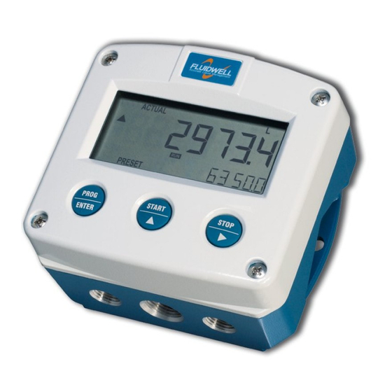
User Manual F490-A-PL INTRODUCTION SYSTEM DESCRIPTION The multi-purpose indicator model F490-A-PL is a microprocessor-driven instrument designed to show the actual process value, such as level, temperature, flow, pressure etc. Fig. 1: The F490 This manual describes the daily use, configuration and installation of the F490-A-PL with analog 4-20 mA input from a sensor, and its available options. -
Page 7: Installation Example
F490-A-PL User Manual Options ● Intrinsic safety (Type XI) ● Panel mount enclosure (Types HB, HC) ● Display backlight (Type ZB). INSTALLATION EXAMPLE Following parts can be recognized in below installation example. Fig. 3: Installation example F490-A-PL 1. Front cover 3. Label 5. -
Page 8: Operation
User Manual F490-A-PL OPERATION This unit may only be operated by authorized and trained personnel who have read and understood this manual, particularly Section 2: Safety [»5] INTRODUCTION This chapter describes the daily use and operation of the F490-A-PL. For this, the F-Series is equipped with a control panel that provides the operator with various functions, information and operating modes. -
Page 9: Backlight (Type Zb)
F490-A-PL User Manual Fig. 4: Example of display information during process 4.2.2 BACKLIGHT (TYPE ZB) The F490-A-PL with Type ZB is equipped with a backlight to illuminate the display for improved readability. DISPLAYED INFORMATION 4.3.1 PROCESS VALUE The main display shows the actual process value, as configured in SETUP- mode ( SETUP 1: DISPLAY The configured unit is indicated on the bottom line of the display. -
Page 10: Configuration
User Manual F490-A-PL CONFIGURATION INTRODUCTION This chapter describes how technicians can use configuration settings to configure the F-Series for optimal functionality. Configuration of the F490-A-PL can be done in SETUP mode, using the front keys. CONFIGURING USING SETUP MODE For an overview of Operating modes, see Section 4.1.1: Operating modes [»8] Changing settings may influence current operation In SETUP mode the unit remains fully operational. -
Page 11: Changing Configuration Settings
F490-A-PL User Manual 5.2.3 CHANGING CONFIGURATION SETTINGS A menu item either contains a value (a number with optionally a decimal point and sign, e.g. -123.45) or a selection list (e.g. L – m - USGAL). After a menu item is selected in the SETUP menu, a new value can be programmed by performing the following steps. -
Page 12: Setup Menu Overview
User Manual F490-A-PL SETUP MENU OVERVIEW DISPLAY DEFAULT UNIT mL - L - nL- M3 - nM3 - mg - g - kg - ton - gal - sgal - igal - lb - bbl - cf - scf - p - rev - °C - °F - K - % - m - mm - cm - mtr - inch - ft - psi - mbar - bar - barg - mmwk - mmwc - cmwk - cmwc - mwk - mwc - inwc - ftwc - Ph - mV - no unit TIME UNIT... -
Page 13: Menu 2: Sensor
F490-A-PL User Manual DISPLAY UNIT Determines the measurement unit for the displayed process value. The following can be selected: mL - L - nL- M3 - nM3 - mg - g - kg - ton - gal - sgal - igal - lb - bbl - cf - scf - p - rev - °C - °F - K - % - m - mm - cm - mtr - inch - ft - psi - mbar - bar - barg - mmwk - mmwc - cmwk - cmwc - mwk - mwc - inwc - ftwc - Ph - mV - no unit... - Page 14 User Manual F490-A-PL SENSOR FILTER The analog output signal of a sensor mirrors the actual process value. This signal is sampled several times per second by the F490-A-PL. Consequently, random and/or fast changes in sensor signal may lead to instable displayed process values. With the help of the filter setting a stable and accurate reading can be obtained.
-
Page 15: Menu 3: Others
F490-A-PL User Manual 5.4.3 MENU 3: OTHERS OTHERS TYPE / MODEL Provides important information on your product. This information may be SOFTWARE VERSION required for maintenance or support. SERIAL NUMBER PASS CODE All SETUP values can be password protected. A four-digit password can be programmed, for example 1234. To disable password protection, enter four zeros (0000). -
Page 16: Installation
User Manual F490-A-PL INSTALLATION ● Mounting, electrical installation, start-up and maintenance of this instrument may only be carried out by trained personnel authorized by the operator of the facility. Personnel must read and understand this Operating Manual before carrying out its instructions. ●... -
Page 17: Handling The F490-A-Pl Enclosure
F490-A-PL User Manual HANDLING THE F490-A-PL ENCLOSURE 6.2.1 IDENTIFICATION The F-Series can be supplied as suitable for Safe Area or Hazardous Area. Suitability for Intrinsic Safety is indicated in the model Type XI. Refer to for identification and installation labels Section 7: Intrinsically safe applications [»25] for Intrinsically Safe applications. -
Page 18: Opening, Assembling And Closing The F-Series
User Manual F490-A-PL Serial number and year of production The serial number can be reviewed on the identification label, the installation label, or in . The production SETUP 3.3: OTHERS > SERIAL NUMBER date is shown on the label and also indicated by the first 4 digits of the serial number representing year and week number (YYWW). -
Page 19: Mechanical Installation
F490-A-PL User Manual MECHANICAL INSTALLATION 6.3.1 MECHANICAL DIMENSIONS Aluminum and stainless steel enclosures Note: Extended back (type HB_) or SS (type HS_) enclosures not available under CSA certification for intrinsically safe installation 75 mm (2.95") 90 mm (3.54") 130 mm (5.12") 112 mm (4.40") 12mm 12mm 30 mm 30 mm... - Page 20 User Manual F490-A-PL Non-metallic enclosures 75 mm (2.95") 130 mm (5.12") 112 mm (4.40") HK back box: (flat bottom) 75 mm (2.95") 118 mm (4.65”) 25mm 25mm D=20mm D=20mm 12mm 12mm 30mm 30mm 24mm 24mm D=12mm D=16mm D=16mm D=20mm 36mm 36mm 0.12”...
-
Page 21: Electrical Installation
F490-A-PL User Manual ELECTRICAL INSTALLATION Hazardous area installations The following chapter gives general information regarding the electrical installation of the F490-A-PL. gives additional specific information Section 7: Intrinsically safe applications [»25] regarding intrinsically safe installation and has priority over the information given in this chapter. -
Page 22: Field Wiring Connections
User Manual F490-A-PL Fig. 10: Grounding connection on rear cover of metal enclosure. 6.4.3 FIELD WIRING CONNECTIONS ● Do ground the aluminum / stainless steel enclosure as indicated in Section 6.4.2: Earth/ground . It is the responsibility of the installer to install, connect and test the ground connections [»21] connections in accordance with the local and (inter)national Rules and Regulations. -
Page 23: Terminal 1: Ground
F490-A-PL User Manual Take notice of all safety and precautionary measures indicated in Section 6.4: Electrical and review installation [»21] Section 6.4.3: Field wiring connections [»22] Section 6.4.4: Power before applying any field or power supply wiring. supply [»22] The following terminal connectors are available on the F490-A-PL. POWER SUPPLY SHIELDING SENSOR... -
Page 24: Terminals 9-10: Backlight Power Supply - Type Zb
User Manual F490-A-PL 6.5.3 TERMINALS 9-10: BACKLIGHT POWER SUPPLY - TYPE ZB To power the optional backlight, a voltage from 20 to 30 V must be connected to the display. The maximum current will be 30mA. Connect the “-“ to terminal 9 and the “+“ to terminal 10. 20 - 30 V DC Fig. 13: Terminals 9-10: Backlight power - Type ZB... -
Page 25: Intrinsically Safe Applications
F490-A-PL User Manual INTRINSICALLY SAFE APPLICATIONS IDENTIFICATION The F490-A-PL can be supplied as suitable for Safe Area or Hazardous Area. Suitability for Intrinsic Safety is indicated in the model Type XI. If Type XI is not indicated your unit is not suitable for Intrinsically Safe applications! Identification label To identify your F0-Series device, all field mount enclosures have a waterproof identification label placed on the outside of the product. -
Page 26: Electrical Installation In Hazardous Areas
User Manual F490-A-PL ELECTRICAL INSTALLATION IN HAZARDOUS AREAS ● shows general information regarding the electrical Section 6.4: Electrical installation [»21] installation of your F490-A-PL. The following sections give additional specific information regarding Intrinsically Safe installation, and overrules information given in other sections. ●... -
Page 27: Electrical Data - Control Drawing
F490-A-PL User Manual 7.2.2 ELECTRICAL DATA - CONTROL DRAWING Control Drawing CD1104.11 SAFE AREA HAZARDOUS AREA TERMINAL CONNECTORS D400 / F400-series I.S. Certified Barrier POWER-SUPPLY Uo=28V to backlight Io=200mA Po=0.96W Optional hazardous location apparatus An appoved Optional hazardous associated location apparatus apparatus Optional hazardous location apparatus... -
Page 28: Installations Based On Atex Or Iecex Certificate
User Manual F490-A-PL 7.2.3 INSTALLATIONS BASED ON ATEX OR IECEX CERTIFICATE Installation instructions ● For installation under ATEX directive: this Intrinsically Safe device must be installed in accordance with ATEX directive 2014/34/EU and product certificate KEMA 03ATEX1075 X. ● For installation under IECEx scheme: this Intrinsically Safe device must be installed in accordance with product certificate IECEx KEM 08.0007X. -
Page 29: Configuration Examples Intrinsically Safe Applications
F490-A-PL User Manual The following terminal connectors are available on the intrinsically safe F490-A-PL Type XI. POWER SUPPLY SENSOR CURRENT SHIELDING GROUND BACKLIGHT LINK SIGNAL INPUT LOOP LINK 4-20 mA ZB 20-30 V DC Fig. 16: Overview of terminal connectors - Type A-PL All electrical connections made to the terminals of the intrinsically safe product (Type XI) must follow the instructions and safety parameters as given in the product certificate. -
Page 30: Maintenance
User Manual F490-A-PL MAINTENANCE GENERAL DIRECTIONS ● Mounting, electrical installation, start-up and maintenance of this instrument may only be carried out by trained personnel authorized by the operator of the facility. Personnel must read and understand this Operating Manual before carrying out its instructions. ●... -
Page 31: Appendix A - Technical Specification
F490-A-PL User Manual APPENDIX A - TECHNICAL SPECIFICATION GENERAL DISPLAY Type High intensity reflective numeric and alphanumeric LCD, UV-resistant Digits 5½ with height 26mm (1”) and 11 with height 8mm (0.31”). Various symbols and measuring units. Dimensions 90 x 40 mm (3.5” x 1.6”) Refresh rate 1/sec Piegraph... -
Page 32: Input
User Manual F490-A-PL OPERATING TEMPERATURE Safe area -30 °C to +70 °C, -22 °F to +158 °F Intrinsically safe -30 °C to +70 °C, -22 °F to +158 °F For EPL Da -30 °C to +50 °C, -22 °F to +122 °F POWER REQUIREMENTS Type PL Input loop powered from 4-20 mA signal. -
Page 33: Operational
F490-A-PL User Manual OPERATIONAL OPERATOR FUNCTIONS Displayed information Process value ● Measuring unit and period ● Piegraph (0 - 100% of set range – can be disabled) ● Sensor input in mA (can be disabled) ● PROCESS VALUE DISPLAY Digits 5½... -
Page 34: Appendix B - Troubleshooting
User Manual F490-A-PL APPENDIX B - TROUBLESHOOTING Table 1 lists and describes how to troubleshoot problems that can occur when installing or operating the F490-A-PL. Table 2 lists internal alarm codes and conditions signaled by a blinking ALARM flag on the display ). -
Page 35: Appendix C - Legal Information
Fluidwell D4- and F4- Series indicators he , February 2022 We, Fluidwell BV, declare under our sole responsibility that the D4- and F4- Series indicators are designed and will operate conform the following applicable European Directives and Harmonised Standards, when installed and operated according to the related manuals:... - Page 36 User Manual F490-A-PL LIST OF CONFIGURATION SETTINGS SETTING DEFAULT DATE: DATE: DISPLAY UNIT TIME UNIT DECIMALS OFFSET SPAN 1600 DIRECTION normal CURRENT PERCENTAGE BARGRAPH SENSOR FORMULA interpolation FILTER 01 (off) CALIBRATE LOW factory CALIBRATE HIGH factory OTHERS TYPE / MODEL F490-A-PL SOFTWARE VERSION 03.xx.xx...
- Page 37 F490-A-PL User Manual NOTES FW_F490-A-PL_M_v0601-01_EN Page 37...
- Page 38 User Manual F490-A-PL Page 38 FW_F490-A-PL_M_v0601-01_EN...
- Page 39 F490-A-PL User Manual FW_F490-A-PL_M_v0601-01_EN Page 39...
- Page 40 Fluidwell bv P.O. Box 6 Voltaweg 23 Website: www.fluidwell.com 5460 AA Veghel 5466 AZ Veghel Find your nearest representative: www.fluidwell.com/representatives the Netherlands the Netherlands © Copyright 2023 - FW_F490-A-PL_M_v0601-01_EN...
Need help?
Do you have a question about the F Series and is the answer not in the manual?
Questions and answers