Table of Contents
Advertisement
Quick Links
Advertisement
Table of Contents

Related Manuals for Fluidwell F070-U


Summary of Contents for Fluidwell F070-U
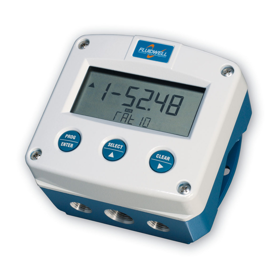
- Page 1 F070-U LEVEL INDICATOR Signal input sensor: 0-10V. Options: Intrinsically Safe. F-Series - Field mounted indicators for safe and hazardous areas. F-Series - Field mounted indicators for safe and hazardous areas. More info: www.fluidwell.com/fseries More info: www.fluidwell.com/fseries...
-
Page 2: Safety Instructions
▪ This unit must be installed in accordance with the EMC guidelines (Electro Magnetic Compatibility). ▪ Do connect a proper grounding to the aluminum casing as indicated if the F070-U has been supplied with the 115-230V AC power-supply type PM. The green / yellow wire between the back-casing and removable terminal-block may never be removed. -
Page 3: About The Operation Manual
This operation manual describes the standard unit as well as most of the options available. For additional information, please contact your supplier. A hazardous situation may occur if the F070-U is not used for the purpose it was designed for or is used incorrectly. Please carefully note the information in this operating manual indicated by the pictograms: A "warning"... -
Page 4: Table Of Contents
Maintenance ........................28 Appendix A: Technical specification ....................29 Appendix B: Problem solving ......................32 Appendix C: Declaration of Conformity ....................33 Appendix D: Control Drawing ......................34 Index of this manual ..........................35 List of configuration settings ......................36 FW-F070-U-M_v0403_05_EN.docx... -
Page 5: Introduction
This manual describes the unit with an analog 0-10V input type from the sensor "-U version". Other versions are available to process a 4-20mA sensor signal. One sensor with a 0-10V signal output can be connected to the F070-U. To power the sensor, several options are available. -
Page 6: Operational
▪ Take careful notice of the " Safety rules, instructions and precautionary measures " in the front of this manual. This chapter describes the daily use of the F070-U. This instruction is meant for users / operators. 2.2. CONTROL PANEL The following keys are available: Fig. - Page 7 SETUP-settings. The signal generated by the connected sensor is measured by the F070-U in the background, whichever screen refresh rate setting is chosen. After pressing a key, the display will be updated very quickly during a 30 second period, after which it will slow-down again.
-
Page 8: Configuration
Operating Manual before carrying out its instructions. ▪ The F070-U may only be operated by personnel who are authorized and trained by the operator of the facility. All instructions in this manual are to be observed. - Page 9 After selecting a sub-function, the next main function is selected by scrolling through all "active" sub- functions (e.g. 1, 11, 12, 13, 14, 1, 2, 3, 31 etc.). The “CLEAR” button can be used to jump a step back if you missed the desired function. FW-F070-U-M_v0403_05_EN.docx...
- Page 10 Note: alterations will only be set after ENTER has been pressed! To return to OPERATOR-level: In order to return to the operator level, PROG will have to be pressed for three seconds. Also, when no keys are pressed for 2 minutes, SETUP will be left automatically. FW-F070-U-M_v0403_05_EN.docx...
- Page 11 CUT-OFF 0.0 - 99.9% CALIBRATE LOW default - calibrate - calibrate set CALIBRATE HIGH default - calibrate - calibrate set OTHERS TYPE / MODEL F070-U SOFTWARE VERSION 03.xx.xx SERIAL NO. xxxxxxx PASS CODE 0000 - 9999 TAGNUMBER 0000000 - 9999999...
- Page 12 OFFSET Enter here the "not measured" quantity which is below the sensor, in case a pressure transducer e.g. is used to measure the quantity. Also, a negative offset can be entered: do press the middle and right button simultaneously. FW-F070-U-M_v0403_05_EN.docx...
- Page 13 OFFSET Enter here the "not measured" height which is below the sensor, in case a pressure transducer e.g. is used to measure the quantity. Also, a negative offset can be entered: do press the middle and right button simultaneously. FW-F070-U-M_v0403_05_EN.docx...
- Page 14 When used with the internal battery option, the user can expect reliable measurement over a long period of time. The F070-U has several smart power management functions to extend the battery life time significantly. Two of these functions can be set:...
- Page 15 FILTER The analog output signal of a sensor does mirror the actual level. This signal is measured several times a second by the F070-U. The value measured is a "snap-shot" of the real level as it will be fluctuating. With the help of this digital filter a stable and accurate reading can be obtained while the filter level can be set to a desired value.
- Page 16 TYPE OF MODEL For support and maintenance it is important to have information about the characteristics of the F070-U. Your supplier will ask for this information in the case of a serious breakdown or to assess the suitability of your model for upgrade considerations.
-
Page 17: Installation
Operating Manual before carrying out its instructions. ▪ The F070-U may only be operated by personnel who are authorized and trained by the operator of the facility. All instructions in this manual are to be observed. - Page 18 1/2"NPT M20 x 1,5 0.12" 0.12" M20 x 1,5 3x 1/2"NPT 25mm 25mm 15 15 M20 x 1,5 M20 x 1,5 4x M20 x 1,5 29.1 mm (1.15”) 115 mm (4.53”) 31 mm (1.22”) Fig. 5: Dimensions Aluminum enclosures. FW-F070-U-M_v0403_05_EN.docx...
- Page 19 118 mm (4.65”) 25mm 25mm D=20mm D=20mm 12mm 12mm 30mm 30mm 24mm 24mm D=12mm D=16mm D=16mm D=20mm 36mm 36mm 0.12” 0.12” D=22mm (0.866") 3x D=22mm (0.866”) 29.1 mm (1.15”) 115 mm (4.53”) 31 mm (1.22”) Fig. 6: Dimensions GRP enclosures. FW-F070-U-M_v0403_05_EN.docx...
- Page 20 ▪ This unit must be installed in accordance with the EMC guidelines (Electro Magnetic Compatibility). ▪ Do ground the aluminum casing properly as indicated, if the F070-U has been supplied with the 115-230V AC power-supply type PM. The green / yellow wire between the back- casing and removable terminal-block may never be removed.
- Page 21 REMARKS: TERMINAL CONNECTORS: Terminals 1-2; Sensor input type U: The F070-U requires a 0-10V sensor signal which will be processed 4 times a second with a 16 bits accuracy. The input is not isolated. The screen of the signal wire must be connected to the common ground terminal...
- Page 22 TYPE: A PF / PM ANALOG 0-10V Fig. 9: Overview of terminal connectors F070-U-(PF / PM) and options. SENSOR SUPPLY Type PF-PM: Sensor supply: 8.2V, 12V or 24 V: With this option, a real power supply for the sensor is available. The sensor can be powered with 8.2, 12 or 24 V DC (max.
- Page 23 400mA@24V DC. Terminals 5-7; Sensor input: The F070-U requires a 0-10V sensor signal which will be processed 4 times a second with a 16 bits accuracy. The input is not isolated. The screen of the signal wire must be connected to the common ground terminal 5.
-
Page 24: Intrinsically Safe Applications
Safety Instructions ▪ Certificates, safety values, control drawing and declaration of compliance can be found in the document named: “Fluidwell F0..-U-XI - Documentation for Intrinsic Safety”. ▪ For installation under ATEX directive: this intrinsically safe device must be installed in accordance with the Atex directive 94/9/EC and the product certificate KEMA 05ATEX1168 X. - Page 25 FWCD-0004. Tamb CSA Certificate nr: CSA.08.2059461 – FM Project ID: 3033306 -40°C ... +70°C Made in Veghel, The Netherlands by Fluidwell bv -40°F ... +158°F KEMA 05ATEX1168 X Battery powered applications: II 1 G Ex ia IIC T4 Replace with certified II 1 D Ex iaD 20 IP 65 / 67 T 100°C...
- Page 26 Page 26 5.3. CONFIGURATION EXAMPLES INTRINSICALLY SAFE APPLICATIONS: Configuration example no. 1 Configuration example IIA - IIB and IIC application - F070-U-PD-XI-ZB HAZARDOUS AREA SAFE AREA TERMINAL CONNECTORS F0-series = max. 30 V Power supply Supply backlight = max. 200 mA...
- Page 27 8. If necessary, get access to the setup menu and make any adjustments to obtain the correct settings. DISPOSAL OF BATTERIES • Batteries pose an environmental hazard. • Do not dispose of as general waste or incinerate. • Return used batteries to a recycling point. FW-F070-U-M_v0403_05_EN.docx...
-
Page 28: Maintenance
Operating Manual before carrying out its instructions. ▪ The F070-U may only be operated by personnel who are authorized and trained by the operator of the facility. All instructions in this manual are to be observed. -
Page 29: Appendix A: Technical Specification
20-30V DC. Power consumption max. 1 Watt. Note: with type PF / PM: internally powered. Note PF / PM The total consumption of the sensor and backlight type ZB may not exceed 400mA@24V DC. Note I.S. application for intrinsically safe applications, consult the safety values in the certificate. FW-F070-U-M_v0403_05_EN.docx... - Page 30 Offset -99,999 to +199,999 units Update time Four times a second. Voltage drop 2.6 Volt. Load impedance 3kOhm Relationship Linear calculation. Note For signal type A and U: external power to sensor is required; e.g. type PD / PF / PM. FW-F070-U-M_v0403_05_EN.docx...
- Page 31 - cm - m - mtr - inch - ft - mmwk - mmwc - cmwk - cmwc - mwk - mwc - inwc - ftwc - mbar - bar - psi - no unit. Decimals 0 - 1 or 2. Percentage Digits 3 digits. Decimals Piegraph Digits 10 segments. Relation to the minimum and maximum input signal (0-100%). FW-F070-U-M_v0403_05_EN.docx...
-
Page 32: Appendix B: Problem Solving
APPENDIX B: PROBLEM SOLVING In this appendix, several problems are included that can occur when the F070-U is going to be installed or while it is in operation. Level / height displays "0 / zero" while a higher signal is available: Check: ▪... -
Page 33: Appendix C: Declaration Of Conformity
Page 33 APPENDIX C: DECLARATION OF CONFORMITY FW-F070-U-M_v0403_05_EN.docx... -
Page 34: Appendix D: Control Drawing
Page 34 APPENDIX D: CONTROL DRAWING FW-F070-U-M_v0403_05_EN.docx... -
Page 35: Index Of This Manual
/ percentage setup-level high current signal input input signal software version installation subfunction intrinsic safety tagnumber keys technical specification level terminal connectors 22, 23 decimals 12, 13 version software measuring unit 12, 13 voltage selection sensor supply Span 12, 13 FW-F070-U-M_v0403_05_EN.docx... -
Page 36: List Of Configuration Settings
_ _ _ _ _ _ _ 64 pass code 0000 65 tagnumber 0000000 Fluidwell bv FW-F070-U-M_v0403_05_EN.docx PO box 6 Voltaweg 23 Website: www.fluidwell.com 5460 AA Veghel 5466 AZ Veghel Find your nearest representative: www.fluidwell.com/representatives The Netherlands The Netherlands Copyright Fluidwell bv - © 2019- FW-F070-U-M_v0403_05_EN.docx...
Need help?
Do you have a question about the F070-U and is the answer not in the manual?
Questions and answers