Table of Contents
Advertisement
Quick Links
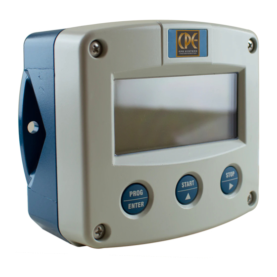
F131-P
BATCH CONTROLLER
with two-stage control, analog and pulse outputs
Signal input flowmeter: pulse, Namur and coil
External controls: start and stop
Digital outputs: two control outputs for two stage control, or
one control output and pulse output ref. total
Analog outputs: (0)4-20mA / 0-10V ref. flow rate
Options: Intrinsically safe, Modbus communication
F-Series - Field mounted indicators for safe and hazardous areas.
More info: www.fluidwell.com/fseries
Advertisement
Table of Contents

Related Manuals for Fluidwell F131-P


Summary of Contents for Fluidwell F131-P
- Page 1 Digital outputs: two control outputs for two stage control, or one control output and pulse output ref. total Analog outputs: (0)4-20mA / 0-10V ref. flow rate Options: Intrinsically safe, Modbus communication F-Series - Field mounted indicators for safe and hazardous areas. More info: www.fluidwell.com/fseries...
- Page 2 Page 2 FW_F131P_v1702_02_EN.docx...
-
Page 3: Safety Instructions
▪ This unit must be installed in accordance with the EMC guidelines (Electro Magnetic Compatibility). ▪ Do connect a proper grounding to the metal enclosure as indicated if the F131-P has an incoming power line which carries a 115-230V AC. The Protective Earth (PE) wire may never be disconnected or removed. -
Page 4: About The Manual
This manual describes the standard unit as well as the available options. For additional information, please contact your supplier. A hazardous situation may occur if the F131-P is not used for the purpose it was designed for or is used incorrectly. Please carefully note the information in this manual indicated by the pictograms: A "warning !"... - Page 5 Control panel 2.2. Operator information and functions Configuration ......................11 3.1. How to program the F131-P 3.2. Setup menu - Settings 3.2.1. Explanation of Setup menu 1 - Preset 3.2.2. Explanation of Setup menu 2 - Flow rate 3.2.3. Explanation of Setup menu 3 - Overrun 3.2.4.
-
Page 6: System Description
SYSTEM DESCRIPTION Functions and features The batch controller model F131-P is a microprocessor driven instrument designed for batching and filling of small up to large quantities as well as displaying the flow rate, the batched total and the accumulated total. - Page 7 Page 7 Configuration of the unit The F131-P is designed for use in many types of applications. For that reason, a setup menu is available to program the F131-P according to your specific requirements. The setup includes several important features, such as K-Factors, engineering units, signal selection, power management (to extend battery life-time), etc.
-
Page 8: Control Panel
• Take careful notice of the "Safety rules, instructions and precautionary measures" in the front of this manual. This chapter describes the daily use of the F131-P . This instruction is meant for users / operators. 2.1. CONTROL PANEL The control panel has three keys. The available keys are: Fig. - Page 9 When you confirm the selection with the PROG/ENTER key, the F131-P will hide the leading zeros in the operational preset menu. It is not possible to enter a preset value which exceeds the batch maximum setting.
- Page 10 No-flow alarm The F131-P offers a no-flow monitoring feature: When the flowmeter does not generate a signal during a certain (preset) time period, the F131-P will shut-off the control output(s) and bring the batch controller in alarm status. The “PAUSE” and “ALARM” indicators come on and NO FLOW is shown. Press the STOP/ key to confirm the alarm status and note that the “PAUSE”...
- Page 11 How to enter the setup menu When the setup menu is protected by a password, the F131-P asks for a password to access the setup menu. When in the operator mode, press and hold the PROG/ENTER key for 7 seconds to access the setup menu.
- Page 12 The START/▲ key and the STOP/► key are used for navigation. The explanation assumes that you are in the submenu PRESET. When you are: • in the first setting and you navigate to the previous setting, the F131-P goes back to the related main menu.
- Page 13 0000000; 111111.1; 22222.22; 3333.333 0000.001 – 9999999 amount pulse total; batch COMMUNIC(ATION) speed 1200; 2400; 4800; 9600 address 1 - 247 mode bus-rtu; bus-asc; off OTHERS model F131-P software version nn:nn:nn serial no. nnnnnnn password 0000 - 9999 tag-nr 0000000 - 9999999 FW_F131P_v1702_02_EN.docx...
- Page 14 Page 14 3.2.1. EXPLANATION OF SETUP MENU 1 - PRESET UNIT This setting is used to select the engineering unit for the indication of the batch total, the accumulated total and the pulse output. When you change the engineering unit, you must recalculate and reprogram the K-factor for the (accumulated) total.
- Page 15 EXPLANATION OF SETUP MENU 4 - ALARM The F131-P offers a no-flow monitoring feature: When the flowmeter does not generate a signal during a certain (preset) time period, the F131-P will shut-off the control output(s) and bring the batch controller in alarm status.
-
Page 16: Battery Mode
When used with the internal battery option (type PB/PC), the user can expect reliable measurement over a long period of time. The F131-P has several smart power management functions to extend the battery life time significantly. Two of these functions can be set. - Page 17 Page 17 3.2.8. EXPLANATION OF SETUP MENU 8 - ANALOG OUTPUT A linear 4-20mA signal (option AB: 0-20mA or option AU: 0-10V) output signal is generated that represents the flow rate. The settings for the flow rate influence the analog output directly. The relationship between the flow rate and the analog output is set with the following settings.
- Page 18 (actual) or accumulated total. RELAYS This submenu is used to set the function of related output. 1-Step: The F131-P is used for one-stage batch control while R2 is used as a scaled pulse output. 2-Step: The F131-P is used for two-stage batch control.
-
Page 19: Installation / Surrounding Conditions
EXPLANATION OF SETUP MENU B - OTHERS For support and maintenance it is important to have information about the characteristics of the F131-P. Your supplier will ask for this information when support is required. MODEL This setting shows the model name. -
Page 20: Dimensions - Enclosure
Page 20 4.3. DIMENSIONS - ENCLOSURE 75 mm (2.95") 112 mm (4.40") 130 mm (5.12") 12mm 12mm 30mm 30mm 24mm 24mm M20 x 1,5 6 x M12 36mm 36mm 25mm 25mm 1/2"NPT 1/2"NPT 1/2"NPT 30mm 30mm 0.12" 0.12" M16 x 1,5 M16 x 1,5 3x 1/2"NPT M20 x 1,5... - Page 21 Page 21 75 mm (2.95") 112 mm (4.40") 130 mm (5.12") HK back box: (flat bottom) 75 mm (2.95") 118 mm (4.65”) 25mm 25mm D=20mm D=20mm 12mm 12mm 30mm 30mm 24mm 24mm D=12mm D=16mm D=16mm D=20mm 36mm 36mm 0.12” 0.12” D=22mm (0.866") 3x D=22mm (0.866”) 38 mm (1.50”)
-
Page 22: Installing The Hardware
4.4.1. GENERAL INSTALLATION GUIDELINES • In the F131-P , different types of bonding and earthing are used. The common (ground) is mostly used for termination of the wire shields and the Protective Earth (PE) is used for electrical safety. • The F131-P that came with a power module type PM; 110V-230V AC or type PD/PF with an option OR (the relays can handle 110V-230V AC) shall be connected to the Protective Earth (PE) stud which is installed in the metal back panel. - Page 23 Do not use the terminal 00 to connect the protective earth wire, the 00 and the common ground terminals are internally connected. Be careful, to prevent damage to equipment when you connect different power supplies (sensor, PLC, etc.). Inside the Fluidwell display, the common grounds are internally connected to each other.
- Page 24 Page 24 4.4.4. PLASTIC (GRP) ENCLOSURE The PE connection The F131-P in a GRP enclosure meets the requirements of class 2 (double insulated). Therefore the incoming PE wire is terminated with an insulating end cap. Type PM (110-230V AC) Type OR (8-24V AC) Type OR (8-30V DC) FW_F131P_v1702_02_EN.docx...
-
Page 25: Terminal Connectors
Page 25 4.4.3. TERMINAL CONNECTORS Refer to Appendix A: Technical Specification Fig. 10: Overview of terminal connectors - Standard configuration and options 4.4.6. SENSOR SUPPLY For option PB/PC; PX; AP: There is no real sensor supply out available. Only a limited power supply is available. This power supply MAY NOT be used to supply the flowmeters electronics, converters etc. - Page 26 5. Close the F131-P . Risk of electrocution - High voltage! Make sure, all the leads to the terminals are disconnected from the F131-P and NEVER connect the mains power supply to the unit when the protection cover has been removed!
- Page 27 Page 27 Terminal 03-04; transistor or relay output R2: This output is designed to drive a low-power device (e.g. relay) to control the batch process. Relay 1 is switched-on during the whole process while relay 2 can be used for two-stage control or as pulse output.
- Page 28 Page 28 Option OR: A mechanical relay output according the functions R1 and R2 is available with this option. Max. switch power 240V-0,5A per output. (Requires power supply type PD/PF/PM). Fig. 14: Terminal connections - Mechanical relay output (typical) Terminal 07-08 POWER SUPPLY - type AP - output loop powered: Connect an external power supply of 8-30VDC to these terminals or a (0)4-20mA loop.
- Page 29 Page 29 An active 0-20mA signal proportional to the flow rate is available with this option. Max. driving capacity 1000 Ohm @ 24VDC. (Requires power supply type PD/PF/PM). Fig. 17: Terminal connections - Active 0-20mA analog output (typical) Option AF: For the Intrinsically safe floating 4-20mA signal: please read Chapter 5.
- Page 30 Pulse-signal PNP / PNP-LP: The F131-P is suitable for use with flowmeters which have a PNP output signal. 3V is offered on terminal 11 which has to be switched by the sensor to terminal 10 (SIGNAL). For a reliable pulse detection, the pulse amplitude has to go above 1.2V.
- Page 31 Fig. 24: Terminal connections - Reed-switch signal input (typical) NAMUR-signal: The F131-P is suitable for flowmeters with an Namur signal. The standard F131-P is not able to power the Namur sensor, as an external power supply for the sensor is required. However, a 8.2V sensor supply voltage (terminal 11) can be provided with power supply type PD, PF, PM.
- Page 32 Page 32 Terminal 12-13; external START: With this function, the batch controller can be started with an external switch. The input must be switched with a potential free contact to the GND-terminal number 12 for at least 0.3 seconds. Fig. 26: Terminal connections - External start (typical) Terminal 15-16;...
-
Page 33: Intrinsically Safe Applications
KEMA 03ATEX1071 U or IECEx KEM 08.0005U is allowed in Hazardous Area. Read chapter 6 for battery replacement instructions. • When the enclosure of the F131-P is made of aluminum alloy, when used in a potentially explosive atmosphere requiring apparatus of EPL Ga, the indicator shall be installed so, that even in the event of rare incidents, an ignition source due to impact or friction sparks between the enclosure and iron/steel is excluded. - Page 34 Page 34 Serial number and year of production This information can be looked-up in the setup menu: Others. Fig. 28: Example serial number (typical) Label information pulse input type – F1xx-..-..-XI (inside and outside the enclosure) Fig. 29: Label information - Intrinsically safe application (typical) FW_F131P_v1702_02_EN.docx...
-
Page 35: Terminal Connectors Intrinsically Safe Applications
3 and 4 and/or terminals 5 and 6; the maximum values for any of those circuits are those as defined for group IIB/IIIC. Terminal connectors F131-P-…-XI: For intrinsically safe applications, consult the safety values in the certificate. - Page 36 5. Close the F131-P. Risk of electrocution - High voltage! Make sure, all the leads to the terminals are disconnected from the F131-P and NEVER connect the mains power supply to the unit when the protection cover has been removed! Type PD-XI Power supply in: 16-30V DC / max.
-
Page 37: Configuration Examples
Page 37 CONFIGURATION EXAMPLES Fig. 33: F131-P-(AP)-(CT)-OT-PC-(PX)-XI - Battery powered - IIB/IIC – IIIC FW_F131P_v1702_02_EN.docx... - Page 38 Page 38 Fig. 34: F131-P-AP-(CT)-OT-(PX)-XI - Output loop powered - IIB/IIC - IIIC FW_F131P_v1702_02_EN.docx...
-
Page 39: Remove The Battery
Page 39 BATTERY REPLACEMENT INSTRUCTIONS 5.4.1. SAFETY INSTRUCTIONS • Handle the battery with care. A mistreated battery can become unsafe. Unsafe batteries can cause (serious) injury to persons. • Only use batteries which are certified for use in hazardous areas. The use of standard batteries in hazardous area's is not safe and prohibited. -
Page 40: Maintenance
Repairs should only be carried out by the manufacturer or his authorized agent. 6.3. REPAIR POLICY I you have any problem with your Fluidwell product and you wish to repair it, please follow the procedure below: a. Obtain a Return Material Authorization (RMA) from your supplier or distributor Together with the RMA, you need to complete a repair form to submit detailed information about the problem. -
Page 41: Appendix A. Technical Specification
Page 41 APPENDIX A. TECHNICAL SPECIFICATION GENERAL Display Type High intensity reflective numeric and alphanumeric LCD, UV-resistant. Digits Seven 17mm (0.67") and eleven 8mm (0.31"). Various symbols and measuring units. Refresh rate User definable: 8 times/sec - 30 secs. Type ZB LCD with LED backlight. - Page 42 Page 42 Terminal connections Type Removable plug-in terminal strip. Wire max. 1.5m m and 2.5m m Data protection Type EEPROM backup of all setting. Backup of running totals every minute. Data retention at least 10 years. Password Configuration settings can be password protected. Hazardous area (optional) Intrinsically safe...
- Page 43 Page 43 OPERATIONAL Operator functions Functions • enter a preset value, • start / interrupt and stop the batch process, • total can be reset to zero. Shown information • preset value and / or flow rate, • running batch total or remaining quantity, •...
-
Page 44: Appendix B. Problem Solving
Page 44 APPENDIX B. PROBLEM SOLVING In this appendix, several problems are included that can occur when the F131-P is going to be installed or while it is in operation. Flowmeter does not generate pulses: Check: ▪ Signal selection; ▪... -
Page 45: Appendix C. Communication Variables
Although most Modbus Masters will support variables that span 2 registers, variables spanning more registers sometimes require you to manually calculate the resulting value. For additional information regarding using your Fluidwell Modbus device, please read the ‘Fluidwell General Modbus Communication Protocol’ and ‘Modbus troubleshooting guide’ that are available through our website or your distributor. - Page 46 Page 46 Runtime variables PDU ADDRESS REGISTER VARIABLE NO. REGISTERS R/W TYPE VALUE / REMARKS [d] 572d 40573 flow rate uint32 0…9999999, Representation: unit, time, [h] 0x23C decimals depending on variables 48, 49, 50 [d] 566d 40567 total R* uint48 0…9999999999, Representation: unit, [h] 0x236 decimals depending on variables 32, 33 [d] 560d...
- Page 47 Page 47 [d] 56 40057 Cut-Off uint16 0.1 – 999.9 seconds, steps of 100ms [h] 0x038 REGISTER TYPE VALUE / REMARKS VARIABLE ADDRESS OVERRUN REGISTERS [d] 194 40195 overrun uint16 0=disable 1=enable [h] 0x0C2 [d] 192 40193 time uint32 0.1 – 999.9 [h] 0x0C0 REGISTER TYPE...
- Page 48 Page 48 [d] 134 40135 pulse for uint16 0=total 1=batch [h] 0x086 REGISTER TYPE VALUE / REMARKS VARIABLE ADDRESS COMMUNICATION REGISTERS [d] 144 40145 speed (Baudrate) uint16 0=1200 1=2400 2=4800 3=9600 [h] 0x090 [d] 145 40146 Modbus address uint16 1…247 [h] 0x091 [d] 146 40147...
-
Page 49: Appendix D. Declaration Of Conformity
Page 49 APPENDIX D. DECLARATION OF CONFORMITY FW_F131P_v1702_02_EN.docx... -
Page 50: Index Of This Manual
Fig. 31: Terminal connections - Intrinsically safe floating 4-20mA analog output (typical) ....36 Fig. 32: Switch position voltage selection option PD-XI ..............36 Fig. 33: F131-P-(AP)-(CT)-OT-PC-(PX)-XI - Battery powered - IIB/IIC – IIIC ........37 Fig. 34: F131-P-AP-(CT)-OT-(PX)-XI - Output loop powered - IIB/IIC - IIIC ........38 FW_F131P_v1702_02_EN.docx... - Page 51 91 relays 1-step 92 preclose 93 width 94 decimals 95 amount 1000 96 pulse total COMMUNICATION 9600 A1 speed A2 address BUS-RTU A3 mode OTHERS B1 model F131-P B2 software version B3 serial nr. B4 password 0000 B5 tag-nr 0000000 FW_F131P_v1702_02_EN.docx...
- Page 52 Page 52 Fluidwell B.V. FW_F131P_v1702_02_EN.docx PO box 6 Voltaweg 23 Website: www.fluidwell.com 5460 AA Veghel 5466 AZ Veghel Find your nearest representative: www.fluidwell.com/representatives the Netherlands the Netherlands © 2017 Fluidwell B.V.: FW_F131P_v1702_02_EN...
Need help?
Do you have a question about the F131-P and is the answer not in the manual?
Questions and answers