Fluidwell F Series Operation Manual
Level indicator with linearization and high / low alarms
Hide thumbs
Also See for F Series:
- Manual (64 pages) ,
- User manual (60 pages) ,
- Operation manual (60 pages)
Table of Contents
Advertisement
Quick Links
F173-A
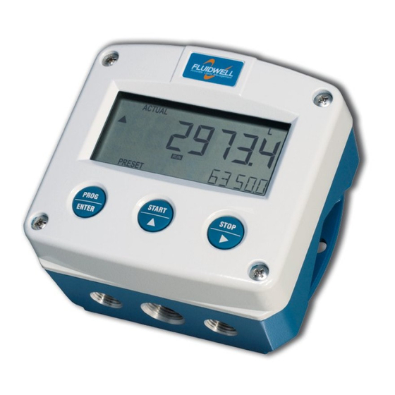
LEVEL INDICATOR WITH LINEARIZATION
AND HIGH / LOW ALARMS
Signal input sensor: (0)4-20mA
Signal outputs: (0)4-20mA/ 0-10V ref. level, height, percentage
Alarm outputs: maximum four level alarms
Options: Intrinsically Safe, Modbus communication, backlight
F-Series - Field mounted indicators for safe and hazardous areas.
More info: www.fluidwell.com/fseries
Advertisement
Table of Contents

Related Manuals for Fluidwell F Series


Summary of Contents for Fluidwell F Series
- Page 1 AND HIGH / LOW ALARMS Signal input sensor: (0)4-20mA Signal outputs: (0)4-20mA/ 0-10V ref. level, height, percentage Alarm outputs: maximum four level alarms Options: Intrinsically Safe, Modbus communication, backlight F-Series - Field mounted indicators for safe and hazardous areas. More info: www.fluidwell.com/fseries...
-
Page 2: Safety Instructions
▪ Intrinsically safe applications: follow the instructions as mentioned in Chapter 5 and consult “Fluidwell F1..-..-XI - Documentation for Intrinsic safety”. DISPOSAL OF ELECTRONIC WASTE • The WEEE Directive requires the recycling of disposed electrical and electronic equipment in the European Union. -
Page 3: About The Operation Manual
WARRANTY AND TECHNICAL SUPPORT For warranty and technical support for your Fluidwell products, visit our internet site www.fluidwell.com or contact us at support@fluidwell.com. Hardware version 03.01.xx Software version 03.05.03... -
Page 4: Table Of Contents
Page 4 CONTENTS MANUAL Safety instructions ..........................2 Disposal of electronic waste ......................... 2 Safety rules and precautionary measures .................... 2 About the operation manual ......................... 3 Warranty and technical support ......................3 Contents manual ........................... 4 Introduction ........................5 1.1. -
Page 5: Introduction
Page 5 INTRODUCTION 1.1. SYSTEM DESCRIPTION OF THE F173-A Functions and features The level indicator F173-A is a microprocessor driven instrument designed to display the linearized level and percentage as well as monitoring the level with four alarm values for a low-low, low, high and high-high level. -
Page 6: Operational
Page 6 Configuration of the unit The F173-A was designed to be implemented in many types of applications. For that reason, a SETUP-menu is available to configure your F173-A according to your specific requirements. SETUP includes several important features, such as Span, measurement units, signal settings etc. All setting as are stored in EEPROM memory and will not get lost in case of power break-down or empty battery. -
Page 7: Operator Information And Functions
Page 7 2.3. OPERATOR INFORMATION AND FUNCTIONS In general, the F173-A will always act at Operator level. The information displayed is dependent upon the SETUP-settings. The signal generated by the connected sensor is measured by the F173-A in the background, whichever screen refresh rate setting is chosen. After pressing a key, the display will be updated very quickly during a 30 second period, after which it will slow-down again. - Page 8 Page 8 ▪ Clear Alarm outputs The Operator has the possibility to clear the alarm outputs, e.g. to turn off an alarm bel. This feature can be enabled individually for each output in SETUP-menu 9. When the clear action is performed, all enabled outputs that are connected to an active alarm status will be cleared. To do so, press the CLEAR/...
-
Page 9: Configuration
Page 9 CONFIGURATION 3.1. INTRODUCTION This and the following chapters are exclusively meant for electricians and non-operators. In these, an extensive description of all software settings and hardware connections are provided. ▪ Mounting, electrical installation, start-up and maintenance of the instrument may only be carried out by trained personnel authorized by the operator of the facility. - Page 10 Page 10 Matrix structure of the SETUP-menu: SCROLLING THROUGH SETUP-MENU Selection function-group and function: SETUP is divided into several function groups and functions. Each function has a unique number, which is displayed below the word "SETUP" at the bottom of the display.
- Page 11 Page 11 To change or a select a value or value: To change a value, use to select the digits and to increase that value. To select a setting, both and can be used. When the new value is not valid, the increase sign or decrease-sign will be displayed while you are programming.
-
Page 12: Overview Functions Setup Menu
Page 12 3.2.2. OVERVIEW FUNCTIONS SETUP MENU SETUP FUNCTIONS AND VARIABLES LEVEL UNIT L - m3 - kg - lb - GAL - USGAL - bbl - no unit DECIMALS 0000000 - 111111.1 - 22222.22 - 3333.333 SPAN 0.000001 - 999,999 unit DECIMALS SPAN 0 - 6 OFFSET... -
Page 13: Explanation Of Setup Menu 1 - Level
Page 13 RELAYS RELAY TEST disable – all off – all on – relay 1 – relay 2 – relay 3 – relay 4 RELAY 1 off - low-low - low - high - high-high - all RELAY 2 off - low-low - low - high - high-high - all RELAY 3 off - low-low - low - high - high-high - all RELAY 4... -
Page 14: Explanation Of Setup Menu 2 - Height
Page 14 EXPLANATION OF SETUP MENU 2 – HEIGHT 3.2.4. If desired the height of the level column can be calculated and displayed. Note: The linearization influences the operator values for level and percentage and not the height. SETUP – 2.1 determines the measurement unit for height:. UNIT The following units can be selected: mm - cm - m - mtr - inch - ft - mmwk - mmwc - cmwk - cmwc... -
Page 15: Explanation Of Setup Menu 4 - Display
Page 15 ALARM HIGH The high alarm is set with this setting. An alarm will be generated as long as the value is higher as this value. ALARM HIGH - HIGH The high-high alarm is set with this setting. An alarm will be generated as long as the value is higher as this value. -
Page 16: Explanation Of Setup Menu 6 - Sensor
Page 16 EXPLANATION OF SETUP MENU 6 – SENSOR 3.2.8. FILTER The analog output signal of a sensor represents the actual level. This signal is measured several times a second by the F173-A. The value measured is a "snap-shot" of the real level as it will be fluctuating. With the help of this digital filter a stable and accurate reading can be obtained while the filter level can be set to a desired value. - Page 17 Page 17 TUNE MAX / 20MA With this setting it is possible to calibrate the input value for 20mA as the signal from the sensor might not be exact 20.0 mA at maximum signal. This function will measure the real output value at maximum level. ▪...
-
Page 18: Explanation Of Setup Menu 7 - Linearization
Page 18 EXPLANATION OF SETUP MENU 7 – LINEARIZATION 3.2.9. The linearization function is available to correct for the tank shape, to approach the real contents of the tank at any height, beyond the general Span entered with setup 13. A maximum of fifteen linearization-positions can be entered while the interpolation will calculate any other position in-between. -
Page 19: Explanation Of Setup Menu 8 - Analog Output
Page 19 % / M-FACTOR The percentage is displayed at the bottom line of the display. 7.1 TO 7.F With value 0% the M-Factor is disabled. The M-Factor is displayed at the top-line of the display. The minimum value to be entered is 0.000001 and the maximum value is 9.999999. Please note that this value has always six decimals while the "dot"... -
Page 20: Explanation Of Setup Menu 9 - Relay Output
Page 20 FILTER This function is used to stabilize the analog output signal. The output value is update eight times per second. With the help of this digital filter a more stable but less actual reading can be obtained. The filter principal is based on three input values: the filter level (01-99), the last analog output value and the last average value. -
Page 21: Explanation Of Setup Menu A - Communication
This product is designed for the connection to a communication network. Products with a communication option do not include cyber security functions. Fluidwell cannot take any responsibility for the cyber security, omissions or errors in the communication safety. To maintain a... -
Page 22: Installation
Page 22 INSTALLATION 4.1. GENERAL DIRECTIONS • Mounting, electrical installation, start-up and maintenance of this device may only be carried out by trained persons authorized by the operator of the facility. Persons must read and understand this manual before carrying out its instructions. •... -
Page 23: Dimensions- Enclosure
Page 23 4.3. DIMENSIONS- ENCLOSURE Aluminum and stainless enclosures (where “H” turns to “HS” for stainless, e.g. HA → HSA): 75 mm (2.95") 112 mm (4.40") 130 mm (5.12") 12mm 12mm 30mm 30mm 24mm 24mm M20 x 1,5 6 x M12 36mm 36mm 25mm... - Page 24 Page 24 75 mm (2.95") 112 mm (4.40") 130 mm (5.12") HK back box: (flat bottom) 75 mm (2.95") 118 mm (4.65”) 25mm 25mm D=20mm D=20mm 12mm 12mm 30mm 30mm 24mm 24mm D=12mm D=16mm D=16mm D=20mm 36mm 36mm 0.12” 0.12” D=22mm (0.866") 3x D=22mm (0.866”) 29.1 mm (1.15”)
-
Page 25: Installing The Hardware
The wire screens shall be terminated at one side to prevent wire loops. Inside of the Fluidwell unit, the different common ground terminals are connected to each other. It is advised, as illustrated, to terminate the wire screens in the vicinity of the sensor and to insulated the wire screen with a shrink tube at the Fluidwell unit side. -
Page 26: Protective Earth (Pe) Connections
Page 26 4.4.2. PROTECTIVE EARTH (PE) CONNECTIONS Inside the unit, different types of bonding and earthing are used. The common ground is mostly used for termination of the wire shields; the Protective Earth (PE) is used for electrical safety. For externally powered installations, route the Protective Earth (PE) grounding conductor into the enclosure together with the incoming power conductors. -
Page 27: Aluminum Enclosure - Field Mounted
Do not use the terminal 00 to connect the protective earth wire, the 00 and the common ground terminals are internally connected. Be careful, to prevent damage to equipment when you connect different power supplies (sensor, PLC, etc.). Inside the Fluidwell display, the common grounds are internally connected to each other. -
Page 28: Aluminum Enclosure - Panel Mounted
Page 28 4.4.4. ALUMINUM ENCLOSURE - PANEL MOUNTED The PE connection The PE connection is made with one of the mounting screws that attaches the front panel to the panel. The PE connection to the metal cover is made with the serrated washers and the mounting screws. -
Page 29: Terminal Connectors
Page 29 4.4.6. TERMINAL CONNECTORS The following paragraphs describe the terminal connections and configurations that are specific for types of supply PM, PF, PD and PX in combination with types OA, OT and OR. For type PD-OS (4 mechanical relay outputs), please consult the addendum to this manual specific for this type: ‘F1xx-A-PD-OS Addendum / Installation Guide’... -
Page 30: Sensor Supply
Page 30 4.4.7. SENSOR SUPPLY For type PB/PC; PX; AP: There is no real sensor supply out available. Only a limited power supply is available. This power supply MAY NOT be used to supply the sensor electronics, converters etc. as it will not provide adequate sustained power ! All energy used by the sensor will directly influence the battery life-time. - Page 31 Page 31 Terminal 03-04; alarm output R2 and Terminal 05-06; alarm output R1: Type OA Two active 24V DC signal alarm outputs are available with this option. Max. driving capacity 50mA@24V per output. (Requires power supply type PD/PF/PM or PX min. 24V DC). Fig.
- Page 32 Page 32 Terminal 07-08; basic POWER SUPPLY - type AP - output loop powered: Connect an external power supply of 8-30VDC to these terminals or a 4-20mA loop. Do connect the "-" to terminal 7 and the "+" to terminal 8. When power is applied to these terminals, the (optional) internal battery will be disabled / enabled automatically to extend the battery life time.
- Page 33 Page 33 Type AP: A passive 4-20mA signal is available with this option. When a power supply is connected but the output is disabled, a 3.5mA signal will be generated. Max. driving capacity 1000 Ohm. This output does loop power the unit as well. Fig.
- Page 34 Page 34 Fig. 20: Terminal connections - Analog signal input – Loop-powered (typical) Terminal 15-16; alarm output R3: Type OA: An active 24V DC signal output is available with this option. Max. driving capacity 50mA@24V per output. (Requires power supply type PD/PF/PM). Fig.
-
Page 35: Intrinsically Safe Applications
Please note • Certificates, safety values, control drawing and declaration of conformity can be found in the document named: “Fluidwell F1..-..-XI - Documentation for Intrinsic safety”. • When installing this device in hazardous areas, the wiring and installation must comply with the appropriate installation standards for your industry. - Page 36 Page 36 Serial number and year of production This information can be looked-up in the setup menu: Others. Fig. 23: Example serial number (typical) Label information – F1xx-..-..-XI (inside and outside the enclosure) Fig. 24: Label information - Intrinsically safe application (typical) FW_F173A_v1901_02_EN.docx...
-
Page 37: Terminal Connectors Intrinsically Safe Applications
Page 37 5.2. TERMINAL CONNECTORS INTRINSICALLY SAFE APPLICATIONS The unit is classified as group IIB/IIIC by default Classification of the unit as group IIC is only possible under the following conditions: The indicator is either supplied by • the internal supply (type PC); •... - Page 38 Page 38 Explanation Intrinsically safe options: Type AF - Intrinsically safe floating 4-20mA analog output - Terminal 7-8: A floating 4-20mA signal is available with this option. When the output is disabled, a 3.5mA signal will be generated. Max. driving capacity 1000 Ohm @ 30V DC. Fig.
-
Page 39: Configuration Examples Intrinsically Safe Applications
Page 39 5.3. CONFIGURATION EXAMPLES INTRINSICALLY SAFE APPLICATIONS Configuration example IIB /IIIC F173-A-AF-CT-OT-(PB)-(PD)-XI HAZARDOUS AREA SAFE AREA TERMINAL CONNECTORS F100-series Modbus communication type CT: TTL I.S. Certified Isolator TTL to: = max. 30 V e.g. PC RS232 = max. 250 mA RS422 = max. - Page 40 Page 40 Configuration example IIB/IIIC and IIC - F173-A-AF-(CT)-OT-PD-XI HAZARDOUS AREA SAFE AREA TERMINAL CONNECTORS F100-series Modbus communication type CT: TTL Please note: communciation type CT is allowed in IIC applications. I.S. Certified Isolator TTL to: = max. 30 V e.g.
-
Page 41: Battery Replacement Instructions
Page 41 BATTERY REPLACEMENT INSTRUCTIONS 5.4.1. SAFETY INSTRUCTIONS • Handle the battery with care. A mistreated battery can become unsafe. Unsafe batteries can cause (serious) injury to persons. • Only use batteries which are certified for use in hazardous areas. The use of standard batteries in hazardous area's is not safe and prohibited. -
Page 42: Maintenance
Repairs should only be carried out by the manufacturer or his authorized agent. 6.3. REPAIR POLICY If you have any problem with your Fluidwell product and you wish to repair it, please follow the procedure below: a. Obtain a Return Material Authorization (RMA) from your supplier or distributor Together with the RMA, you need to complete a repair form to submit detailed information about the problem. -
Page 43: Appendix A: Technical Specification
Page 43 APPENDIX A: TECHNICAL SPECIFICATION GENERAL Display Type High intensity reflective numeric and alphanumeric LCD, UV-resistant. Digits Seven 17mm (0.67") and eleven 8mm (0.31"). Various symbols and measuring units. Refresh rate User definable: 8 times/sec - 30 secs. Type ZB LCD with LED backlight. - Page 44 Page 44 Sensor excitation Type PB / PC / PX Not suitable to power a (0)4-20mA sensor Type PD 3; 8.2; 12; 24V DC - max. 50mA@24V DC Type PD-XI The sensor supply voltage is according to power supply (internally connected) Type PF / PM 3;...
- Page 45 Page 45 Communication option Protocol bus-rtu; bus-asc Speed 1200 - 2400 - 4800 - 9600 – 9600HP - 19200 - 38400 Addressing 1 - 247 Type CB RS232 Type CH RS485 2-wire Type CI RS485 4-wire Type CT TTL Intrinsically safe communication. Type CX no communication.
-
Page 46: Appendix B: Problem Solving
Page 46 APPENDIX B: PROBLEM SOLVING In this appendix, several problems are included that can occur when the F173-A is going to be installed or while it is in operation. Analog output does not function properly: Check: ▪ SETUP 8.1: is the function enabled? ▪... -
Page 47: Appendix C: Communication Variables
Page 47 APPENDIX C: COMMUNICATION VARIABLES GENERAL The product is fitted with the Modbus communication protocol and can be equipped with various physical interfaces like RS485 and RS232 (please see device datasheet for available options). The tables below show the various variables that can be accessed through the communication. Currently, the function codes supported are: •... - Page 48 Page 48 REGISTER VARIABLE TYPE VALUE / REMARKS ADDRESS HEIGHT REGISTERS [d] 224 40225 unit uint16 0=m 5=ft 10=mwk 15=bar [h] 0x0E0 1=mm 6=mmwk 11=mwc 16=psi 2= cm 7=mmwc 12=inwc 17=none 3=mtr 8=cmwk 13=ftwc 4=inch 9=cmwc 14=mbar [d] 226 40227 decimals uint16 0…3 [h] 0x0E2...
- Page 49 Page 49 REGISTER VARIABLE TYPE VALUE / REMARKS ADDRESS DISPLAY REGISTERS [d] 68 40069 alarm set uint16 0=operate 1=setup [h] 0x044 [d] 64 40065 display function uint16 0= L (evel) 2=L+P 4=H+P [h] 0x040 1= L+H 3=H (eight) 5=P (ercent) [d] 67 40068 backlight brightness...
- Page 50 Page 50 REGISTER VARIABLE TYPE VALUE / REMARKS ADDRESS ANALOG OUTPUT REGISTERS [d] 112 40113 analog output uint16 0=disable 1=enable [h] 0x070 [d] 124 40125 analog output input value uint16 0= level 1=height 2=percent [h] 0x07C [d] 113 40114 minimum value uint32 0…9999999 [h] 0x071 Representation: unit, time, decimals...
- Page 51 Page 51 [d] 25 40026 reboot uint16 Returns 0 on read. [h] 0x019 Write 0xA50F for unit restart Write 0x5AF0 for factory settings REGISTER VARIABLE TYPE VALUE / REMARKS OTHERS ADDRESS REGISTERS [d] 173 40174 model number uint16 0…9999 [h] 0x0AD [d] 160 40161 model suffix...
-
Page 52: Appendix D. Declaration Of Conformity
Page 52 APPENDIX D. DECLARATION OF CONFORMITY FW_F173A_v1901_02_EN.docx... -
Page 53: Index Of This Manual
Page 53 INDEX OF THIS MANUAL actual settings 57, 58, 59 Intrinsically Safe options alarm IP classification set alarm operator level keys analog level disable/enable alarm floating output. alarm value intrinsically safe output. decimals level min. decimals Span tune / calibrate measuring unit Analog output Span... - Page 54 Page 54 LIST OF CONFIGURATION SETTINGS SETTING DEFAULT DATE : DATE : 1 - LEVEL 1.1 unit 1.2 decimals 0000000 1.3 span 1600 1.4 decimals span 1.5 offset 2 - HEIGHT 2.1 unit 2.2 decimals 0000000 2.3 span 1600 2.4 decimals span 2.5 offset 3 - ALARM 3.1 input...
- Page 55 Page 55 LIST OF CONFIGURATION SETTINGS (CONT) SETTING DEFAULT DATE : DATE : 7 - LINEARIZATION 7.1 percentage % 0.0% M-Factor 1.000000 7.2 percentage % 0.0% M-Factor 1.000000 7.3 percentage % 0.0% M-Factor 1.000000 7.4 percentage % 0.0% M-Factor 1.000000 7.5 percentage % 0.0% M-Factor...
- Page 56 B.3 serial no xxxxxxx B.4 password 0000 B.5 tagnumber 0000000 Fluidwell B.V. FW_F173A_v1901_02_EN.docx PO box 6 Voltaweg 23 Website: www.fluidwell.com 5460 AA Veghel 5466 AZ Veghel Find your nearest representative: www.fluidwell.com/representatives the Netherlands the Netherlands © 2021 Fluidwell B.V.: FW_F173A_v1901_02_EN.docx...
Need help?
Do you have a question about the F Series and is the answer not in the manual?
Questions and answers