Table of Contents
Advertisement
Quick Links
A S S E M B L Y M A N U A L
" Graphics and speciications may change without notice ".
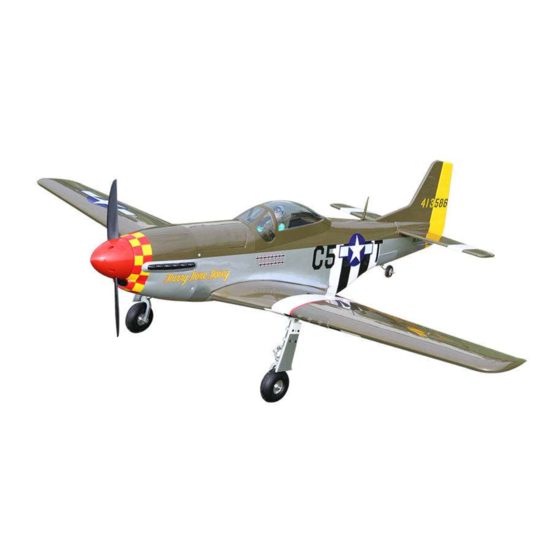
Code: SEA276
Speciications:
Wingspan---------------56.3 in (143 cm).
Wing area---------------563.6 sq.in ( 36.4q.dm).
Weight-------------------6.6-6.8 lbs ( 3.0-3.1 kg).
Length-------------------45.3 in (115.1 cm).
Engine-------------------10-15cc
Radio--------------------7 channels with 7 servos.
1
Advertisement
Table of Contents

Related Manuals for Seagull Models SEA276


Summary of Contents for Seagull Models SEA276
- Page 1 A S S E M B L Y M A N U A L “ Graphics and speciications may change without notice ”. Code: SEA276 Speciications: Wingspan---------------56.3 in (143 cm). Wing area---------------563.6 sq.in ( 36.4q.dm). Weight-------------------6.6-6.8 lbs ( 3.0-3.1 kg).
-
Page 2: Kit Contents
P-51D MUSTANG Instruction Manual. INTRODUCTION. hank you for choosing the P-51D MUSTANG ARF by SG MODELS. he P-51D MUSTANG was designed with the intermediate/advanced sport lyer in mind. It is a semi scale airplane which is easy to ly and quick to assemble. he airframe is conventionally built using balsa, plywood to make it stronger than the average ARF, yet the design allows the aeroplane to be kept light. -
Page 3: Additional Items Required
HINGING THE FLAP. KIT CONTENTS. SEA276 P-51D MUSTANG Note : he control surfaces, including the ai- 1. Fuselage lerons, elevators, and rudder, are prehinged 2. Wing set with hinges installed, but the hinges are not glued in place. It is imperative that you prop- 3. -
Page 4: Hinging The Aileron
P-51D MUSTANG Instruction Manual. 4) Delect the lap and completely saturate 8) Ater both lap are securely hinged, irmly each hinge with thin C/A glue. he lap’s grasp the wing panel and lap to make sure front surface should lightly contact the wing the hinges are securely glued and cannot during this procedure. - Page 5 5) Turn the wing panel over and delect the aileron in the opposite direction from the opposite side. Apply thin C/A glue to each hinge, making sure that the C/A penetrates into both the aileron and wing panel. 6) Using C/A remover/debonder and a pa- Hinge.
-
Page 6: Wing Assembly
P-51D MUSTANG Instruction Manual. Epoxy. Flap control horn. WING ASSEMBLY. Please see below pictures. Epoxy. Aileron control horn. INSTALL FLAP CONTROL HORN. Install the lap control horn using the same method as same as the aileron con- trol horns. Attach the aluminum tube into wing. Fiberglass control horn Epoxy. -
Page 7: Installing The Aileron Servos
Because the size of servos difer, you may need to adjust the size of the precut opening in the mount. he notch in the sides of the mount allow the servo lead to pass through. 1) Place the servo between the mounting blocks and space it from the hatch. - Page 8 P-51D MUSTANG Instruction Manual. 4) Use dental loss to secure the connec- tion so they cannot become unplugged. 5) Secure the servo to the aileron hatch using Phillips screwdriver and the screws provided with the servo. 6) Apply 1-2 drops of thin C/A to each of the mounting tabs.
-
Page 9: Aileron Pushrod Installation
Mark. INSTALLING THE FLAP SERVO. Bend at the mark Repeat the procedure for the lap servo. M2 lock nut. Metal clevis. Snap keeper. Servo arm. Snap keeper. AILERON PUSHROD INSTALLATION. Please see below pictures. Nylon Snap keeper. Hex Nut. Fuel tubing. Use a felt tip pen to mark the wire where it crosses the hole. - Page 10 P-51D MUSTANG Instruction Manual. INSTALLING THE FLAP PUSHROD. Repeat the procedure for the aileron pushrod. INSTALLING RETRACTABLE LANDING GEAR. Locate items necessary to install Sprin Landing Gear. You use this fork set JP ER-120-84degree.
- Page 11 C/A glue M3x4mm M3x25mm...
- Page 12 P-51D MUSTANG Instruction Manual. M3x10mm M3x4mm Collar M3x4mm...
- Page 13 PLASTIC COVER ASSEMBLY.
-
Page 14: Installing The Fuselage Servos
P-51D MUSTANG Instruction Manual. THROTTLE SERVO ARM INSTALLATION. Epoxy. Install the Z-bend in the servo arm as same as picture below: INSTALLING THE FUSELAGE SERVOS. Because the size of servos difer, you may need to adjust the size of the precut opening in the mount. -
Page 15: Installing The Stopper Assembly
INSTALLING THE STOPPER ASSEMBLY. 1) Using a modeling knife, carefully cut of the rear portion of one of the 3 nylon tubes leaving 1/2” protruding from the rear of the stopper. his will be the fuel pick up tube. Trim and cut. 2) Using a modeling knife, cut one length of silicon fuel line. -
Page 16: Fuel Tank Installation
P-51D MUSTANG Instruction Manual. Vent tube. Fuel pick up tube. Fuel fill tube. 3) Carefully bend the second nylon tube up at a 45º angle. his tube is the vent tube. 4) Test it the stopper assembly into the tank. It may be necessary to remove some of the lashing around the tank opening using a modeling knife. -
Page 17: Mounting The Engine
MOUNTING THE ENGINE. 1) Position the engine with the drive washer (127mm) forward of the irewall as shown. Blow through one of the lines to ensure the fuel lines have not become kinked inside the fuel tank compartment. Air should low through easily. - Page 18 P-51D MUSTANG Instruction Manual. 4) On the ire wall has the location for the throttle pusshrod tube (pre-drill). 5) Slide the pushrod tube in the irewall and guide it through the fuel tank mount. Use medium C/A to glue the tube to the irewall and the fuel tank mount.
- Page 19 2) Use a drill and drill bit to drill the holes 4) Slide the muler screws through the for the cowl mounting screws. Make sure engine. Place the mulr extension and the cowl position is correct before drill- gaskets included with the engine on the ing each hole.
- Page 20 P-51D MUSTANG Instruction Manual. 3) Attach the electric motor box to the irewall suitable with the cross lines drawn on the electric motor box and ire- wall. Using M4x20mm to secure the mo- tor box to the irewall. Please see pictures below.
- Page 21 4 mm Balsa stick. Epoxy 6) Attach the speed control to the side of the motor box using two-sided tape and tie wraps. Connect the appropriate leads from the speed control to the mo- tor. Make sure the leads will not interfere Blind nut.
-
Page 22: Hinging The Elevators
P-51D MUSTANG Instruction Manual. HINGING THE ELEVATORS. 1) Locate the items for this section of the manual. INSTALLING THE SPINNER. 2) Carefully remove the elevator from one of the horizontal stabilizer panels. Note the position of the hinges. 3) Remove each hinge from the horizon- tal stabilizer panel and elevator and place a T-pin in the center of each hinge.Epoxy the wire elevator joiner into the pre-... -
Page 23: Installing The Horizontal Stabilizer
2) Using a modeling knife, carefully re- INSTALL ELEVATOR CONTROL HORN. move the covering at mounting slot of horizontal stabilizer ( both side of fuse- lage). Cut. Fiberglass control horn 3) Slide the stabilizer into place in the precut slot in the rear of the fuselage. he stabilizer should be pushed irmly against the front of the slot. -
Page 24: Hinging The Rudder
P-51D MUSTANG Instruction Manual. Trim and cut When cutting through the covering to remove it, cut with only enough pressure to only cut through the covering itself. Cut- ting into the balsa structure may weaken HINGING THE RUDDER. Glue the top two rudder hinges in place 6) Using a modeling knife, carefully re- using the same techniques used to hinge move the covering that overlaps the sta-... -
Page 25: Installing Vertical Stabilizer
Fill Epoxy Epoxy. 2) Slide the vertical stabilizer into the slot in the top of the fuselage. he rear edge of the stabilizer should be lush with the rear edge of the fuselage and the lower rudder hinge should engage the precut hinge slot in the lower fuselage. -
Page 26: Elevator Pushrod Installation
P-51D MUSTANG Instruction Manual. ELEVATOR PUSHROD INSTALLATION. Vertical Stabilizer. Horizontal 90º 1) Install the elevator control horn using Stabilizer. the same method as with the aileron con- trol horns. 2) Position the elevator control horn on the both side of elevator. Elevator control horn. -
Page 27: Rudder Pushrod Installation
M2 lock nut. M2 clevis. M2 lock nut. M2 clevis. Pen. Nylon Snap Keeper. RUDDER PUSHROD INSTALLATION. Repeat steps as same as steps done for elevator. -
Page 28: Mounting The Tail Wheel
P-51D MUSTANG Instruction Manual. MOUNTING THE TAIL WHEEL. - Page 29 INSTALLATION PILOT AND CANOPY. 1) Locate items necessary to install pilot, seats. 2) A scale pilot is included with this ARF. he Pilot included itting well to the cockpit. (or you can order others scale pilot igures made by SG Models. hey are available at SG Models distributors.) If you are going to install a pilot igure, please use a sanding bar to sand the base...
-
Page 30: Apply The Decals
P-51D MUSTANG Instruction Manual. INSTALLING BATTERY - RECEIVER. 1) Plug the servo leads and the switch lead into the receiver. Plug the battery pack lead into the switch also. 130mm 2) Wrap the receiver and battery pack in the protective foam rubber to protect them from vibration. - Page 31 5) Tighten the antenna is removeable so you can install it at the lying ield to pre- vent damage in transporting. Antenna. BALANCING. 1) It is critical that your airplane be balanced correctly. Improper balance will cause your plane to lose control and crash.
-
Page 32: Control Throws
P-51D MUSTANG Instruction Manual. With the wing attached to the fuselage, all parts of the model installed ( ready to ly), and empty fuel tanks, hold the mod- el at the marked balance point with the 103-114mm stabilizer level. Lit the model. If the tail drops when you lit, the model is “tail heavy”... -
Page 34: Flight Preparation
P-51D MUSTANG Instruction Manual. FLIGHT PREPARATION. PREFLIGHT CHECK. Check the operation and direction 1) Completely charge your trans- of the elevator, rudder, ailerons and mitter and receiver batteries before throttle. your irst day of lying. A) Plug in your radio system per the 2) Check every bolt and every glue manufacturer’s instructions and turn joint in the...
Need help?
Do you have a question about the SEA276 and is the answer not in the manual?
Questions and answers