Table of Contents
Advertisement
Quick Links
A S S E M B L Y M A N U A L
Code: SEA260
" Graphics and speciications may change without notice " .
Speciications:
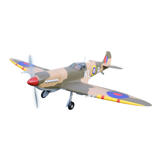
Wingspan---------------86.4 in (219.5 cm).
Wing area---------------1325.3 sq.in (85.5 sq.dm).
Weight-------------------17.6-18.1 lbs (8.0-8.2 kg).
Length-------------------72.0 in (183 cm).
Gasoline Engine--------50-55cc
Radio--------------------8 channels with 8 servos.
Electric conversion: Optional.
1
Advertisement
Table of Contents

Related Manuals for Seagull Models SUPERMARINE SPITFIRE MK VB AB910


Summary of Contents for Seagull Models SUPERMARINE SPITFIRE MK VB AB910
- Page 1 A S S E M B L Y M A N U A L Code: SEA260 “ Graphics and speciications may change without notice “ . Speciications: Wingspan---------------86.4 in (219.5 cm). Wing area---------------1325.3 sq.in (85.5 sq.dm). Weight-------------------17.6-18.1 lbs (8.0-8.2 kg). Length-------------------72.0 in (183 cm).
-
Page 2: Kit Contents
Instruction Manual. SPITFIRE 55cc INTRODUCTION. hank you for choosing the SPITFIRE 55cc ARF by SG MODELS . he SPITFIRE 55cc was designed with the intermediate/advanced sport lyer in mind. It is a semi scale airplane which is easy to ly and quick to assemble. he airframe is conventionally built using balsa, ply- wood to make it stronger than the average ARF, yet the design allows the aeroplane to be kept light. -
Page 3: Additional Items Required
KIT CONTENTS. HINGING THE FLAP. SEA260 SPITFIRE 55cc SEA26001 Fuselage SEA26002 Wing set SEA26003 Tail set SEA26004 Canopy SEA26005 Cowling SEA26006 Pilot SEA26007 Aluminum wing tube ADDITIONAL ITEMS REQUIRED. � 55cc gasoline engine. � Computer radio with 10 servos. � Glow plug to suit engine. - Page 4 SPITFIRE 55cc Instruction Manual. INSTALL THE AILERONS . Please see pictures below.. Insert all four hinges in the ailerons at this time. Make sure hinges move up and down in right direction and not side to side ! Epoxy. Remove the ailerons from the wing and remove the hinges.
- Page 5 Be sure to test the aileron hinges once INSTALL THE AILERONS you insert them. Ensure that the hinge CONTROL HORN. pockets line up, and that the hinges move freely before the epoxy dries. Fiberglass control horn Epoxy. Aileron control horn. Epoxy.
- Page 6 Instruction Manual. SPITFIRE 55cc Epoxy. Epoxy. Epoxy. INSTALL ELEVATOR HINGES. Test fit the hinges into the elevator, and then the hinges into the horizontal INSTALL ELEVATOR CONTROL HORN. stabilzer. Ensure that the hinge pockets line up, and that the hinges move freely Epoxy.
-
Page 7: Installing The Fuselage Servos
Epoxy. Rudder iberglass control horn. INSTALLING THE FUSELAGE SERVOS. Because the size of servos difer, you may need to adjust the size of the precut opening in the mount. he notch in the sides of the mount allow the servo lead to pass through. -
Page 8: Installing The Stopper Assembly
Instruction Manual. SPITFIRE 55cc hrottle servo arm. Trim and cut. Rudder and steering servo arm. INSTALLING THE RECEIVER SWITCH. Install the switch into the precut hole in the side, in the fuselage. 3/32” Hole. Switch. INSTALLING THE STOPPER ASSEMBLY. 1) Using a modeling knife, carefully cut of the rear portion of one of the 3 nylon tubes leaving 1/2”... -
Page 9: Fuel Tank Installation
FUEL TANK INSTALLATION. You should mark which tube is the vent and which is the fuel pickup when you attach fuel tubing to the tubes in the stopper. Once the tank is installed inside the fuselage, it may be diicult to determine which is which. 7) Slide the fuel tank into the fuselage. -
Page 10: Mounting The Engine
Instruction Manual. SPITFIRE 55cc Vent tube. Fuel ill tube. Fuel pick up tube. 9) Connect the lines from the tank to the en- gine and muler. he vent line will connect to the muler and the line from the clunk to 5x70 mm the carburetor. - Page 11 ELECTRIC POWER CONVERSION. 1) Reinstall the servo horn by sliding the connector over the pushrod wire. Center 1) Locate the items necessary to installl the throttle stick and trim and install the the electric power conversion included servo horn perpendicular to the servo with your model.
- Page 12 Instruction Manual. SPITFIRE 55cc 3) Attach the electric motor box to the irewall suitable with the cross lines drawn on the electric motor box and ire- wall. Using M5x25mm to secure the mo- tor box to the irewall. Please see pictures below.
- Page 13 COWLING. 5) Attach the speed control to the side of the motor box using two-sided tape Please see these below pictures. and tie wraps. Connect the appropriate leads from the speed control to the mo- tor. Make sure the leads will not interfere with the operation of the motor.
-
Page 14: Installing The Spinner
Instruction Manual. SPITFIRE 55cc 2) Slide the cowl in position on the fuselage. Use M3x10mm socket head cap screws with washers to secure the cowling to the fuselage. 1) Carefully align the cowling on the air- hen, use thread locker glue to help prevent plane. -
Page 15: Installing The Aileron Servos
he propeller should not touch any 1) Using a small weight (Weighted fuel part of the spinner cone. If it does, use a pick-up works well) and string, feed the sharp modeling knife and carefully trim string through the wing as indicated. away the spinner cone where the propel- ler comes in contact with it. - Page 16 Instruction Manual. SPITFIRE 55cc 5) Use dental loss to secure the connec- tion so they cannot become unplugged. 6) Secure the servo to the aileron hatch using Phillips screwdriver and the screws provided with the servo. 7) Apply 1-2 drops of thin C/A to each of the mounting tabs.
- Page 17 INSTALLING ELEVATOR SERVOS. Elevator servos assembly as below pic- tures. 9) Set the aileron hatch in place and use a Phillips screw driver to install it with four wood screws. 2x10mm INSTALLING THE FLAP SERVO. Repeat the procedure for the lap servo.
-
Page 18: Aileron Pushrod Installation
Instruction Manual. SPITFIRE 55cc AILERON PUSHROD INSTALLING THE FLAP PUSHROD. INSTALLATION. Repeat the procedure as aileron push- Please see below pictures. rod. 70mm M3 lock nut. M3 clevis. 80mm M3 clevis. M3 lock nut. -
Page 19: Installing The Elevator Pushrod
INSTALLING THE ELEVATOR PUSHROD. 60mm M3 lock nut. M3 clevis. INSTALLING RETRACTABLE LANDING GEAR. Locate items necessary to install Sprin Landing Gear. You use this fork set JP ER-150-95 degree. - Page 20 Instruction Manual. SPITFIRE 55cc 3x10mm. 3x20mm. 3x4mm.
- Page 21 Collar. M3x4mm.
-
Page 22: Installing The Horizontal Stabilizer
Instruction Manual. SPITFIRE 55cc INSTALLING RUDDER HINGE. INSTALLING THE HORIZONTAL STABILIZER. he rudder hinge assembly as below pic- tures. -
Page 23: Rudder Pushrod Installation
3x10mm RUDDER PUSHROD INSTALLATION. Locate item necessary to install ruder pushrod. Crimp. M3 clevis. Metal connector. Cable end. -
Page 24: Mounting The Tail Wheel
Instruction Manual. SPITFIRE 55cc MOUNTING THE TAIL WHEEL. Crimp. M3 clevis. Metal connector. Cable end. Collar. - Page 25 INSTALLATION PILOT AND CANOPY. 1) Locate items necessary to install pilot, seats. 2) A scale pilot is included with this ARF. he Pilot included itting well to the cockpit. (or you can order others scale pilot igures made by SG Models. hey are available at SG Models distributors.) C/A glue.
-
Page 26: Apply The Decals
Instruction Manual. SPITFIRE 55cc For the larger decals we recommend a “wet” application method - 1) Peel the paper backing sheet of the decal.; 2) Epoxy. Use a soapy water product (like win- dow cleaner) to spray the adhesive side of the decal. - Page 27 4) he last detail is to install the antenna onto the fuselage. Use a hobby knife to cut a slot in the top of the fuselage for the antenna. Remove covering to see hole. 5) Tighten the antenna is removeable so you can install it at the lying ield to pre- vent damage in transporting.
- Page 28 Instruction Manual. SPITFIRE 55cc ATTACHMENT WING- FUSELAGE. Attach the aluminum tube into fuselage. Wing tube. Insert two wing panels as pictures below. 4x12mm Wing bolt.
- Page 29 Insert canopy hatch on the fuselage as Accurately mark the balance point on below pictures. the top of the wing on both sides of the fuselage. he balance point is located 122mm back from the leading edge of the wing at the wing root. his is the bal- ance point at which your model should balance for your irst lights.
-
Page 30: Control Throws
Instruction Manual. SPITFIRE 55cc CONTROL THROWS. Rudder: Ailerons: 122mm High Rate : High Rate : Up : 18mm Right : 30mm Down : 18mm Let : 30mm Low Rate : Low Rate : Up : 13mm Right : 25mm Down : 13mm Let : 25mm Elevator: Flap:... -
Page 31: Flight Preparation
FLIGHT PREPARATION. PREFLIGHT CHECK. 1) Completely charge your trans- Check the operation and direction mitter and receiver batteries before of the elevator, rudder, ailerons and your irst day of lying. throttle. 2) Check every bolt and every glue A) Plug in your radio system per the joint in the SPITFIRE 55cc to en- manufacturer’s instructions and turn sure that everything is tight and well... - Page 32 Instruction Manual. SPITFIRE 55cc If you have any queries, or are interested in our products, please feel free to contact us Factory : 12/101A - Hamlet 4 - Le Van Khuong Street - Dong hanh Ward - Hoc Mon District - Ho Chi Minh City - Viet Nam. Oice : 62/8 Ngo Tat To Street - Ward 19 - Binh hanh District - Ho Chi Minh City - Viet Nam Phone : 848 - 37114542 or 848- 36018777...
Need help?
Do you have a question about the SUPERMARINE SPITFIRE MK VB AB910 and is the answer not in the manual?
Questions and answers