Advertisement
Table of Contents
- 1 Table of Contents
- 2 Specifications
- 3 Important Safety Instructions
- 4 Symbols
- 5 Know Your Robotic Mower
- 6 Assembly
- 7 Battery Pack and Charger
- 8 Operation
- 9 Maintenance
- 10 Environmentally Safe Battery Disposal
- 11 Troubleshooting
- 12 Lawnmaster ® Warranty
- 13 Exploded View
- 14 Parts List
- 15 Notes
- Download this manual
Operator's Manual
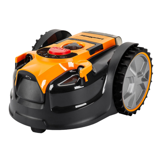
MX 24V Lithium-Ion Robotic Lawn Mower VBRM601YCM
Save this manual for future reference
* Maximum initial battery workload voltage (measured without a workload) is 24 volts.
Nominal voltage is 21.6 volts.
Battery Model Number is 24LB4005-CN
Charger Model Number is 24LFC14-ETL
Read all safety rules and instructions carefully before operating this tool.
Distributed By: Suzhou Cleva Electric Appliance Co., Ltd.
NO.8 Ting Rong Street 215122 Suzhou - China
Advertisement
Table of Contents

Subscribe to Our Youtube Channel
Related Manuals for LawnMaster VBRM601YCM


Summary of Contents for LawnMaster VBRM601YCM
- Page 1 Operator's Manual MX 24V Lithium-Ion Robotic Lawn Mower VBRM601YCM Save this manual for future reference * Maximum initial battery workload voltage (measured without a workload) is 24 volts. Nominal voltage is 21.6 volts. Battery Model Number is 24LB4005-CN Charger Model Number is 24LFC14-ETL Read all safety rules and instructions carefully before operating this tool.
-
Page 2: Table Of Contents
TABLE OF CONTENTS SPECIFICATIONS IMPORTANT SAFETY INSTRUCTIONS SYMBOLS 10-12 KNOW YOUR ROBOTIC MOWER 13-14 ASSEMBLY 15-16 BATTERY PACK AND CHARGER 17-19 OPERATION 20-29 MAINTENANCE 30-33 ENVIRONMENTALLY SAFE BATTERY DISPOSAL TROUBLESHOOTING 35-39 ® LAWNMASTER WARRANTY EXPLODED VIEW PARTS LIST NOTES 43-44... -
Page 3: Specifications
SPECIFICATIONS DIMENSIONS Length 16.73'' (42.5 cm) Width 13.78'' (35 cm) Height 8.66'' (22 cm) Weight (Without 4.0Ah Battery) 13.4 lbs (6.1 kg) MOWING Voltage 24 V D.C. No-load Speed 3500 RPM Cutting System 3 Pivoting Cutting Blades Cutting Width 6'' (15.5 cm) Cutting Height Adjustment 1''-2.5'’... - Page 4 FIRST OPERATION The VBRM601YCM is designed to detect grass and move into areas it identifies as grass. If it cannot see a clear boundary it will continue to move into areas off the lawn and into plants that it may identify as grass.
-
Page 5: Important Safety Instructions
IMPORTANT SAFETY INSTRUCTIONS IMPORTANT! READ CAREFULLY BEFORE USE. KEEP FOR FUTURE REFERENCE. TRAINING ■ Read the instructions carefully. Be familiar with the controls and the proper use of the machine. ■ Never allow people unfamiliar with these instructions or children to use the machine. Local regulations may restrict the age of the operator. - Page 6 IMPORTANT SAFETY INSTRUCTIONS ■ Never pick up or carry a machine while the motor is running. ■ Always remove the safety key: - Before clearing a blockage. - Before checking, cleaning or working on the machine. ■ It is not permitted to modify the original design of the mower. All modifications are made at your own risk.
- Page 7 ■ IMPORTANT! It is recommended to keep the original packaging to avoid damage during transportation over long distances. BATTERY PACK ® ■ The battery pack is only compatible with LawnMaster 24LFC14-ETL, 24LFC02-ETL or 24LSC01- ETL chargers. ■ Recharge only with the charger specified by the manufacturer and listed in this manual. A charger that is suitable for one type of battery pack may create a risk of fire when used with another battery pack.
- Page 8 IMPORTANT SAFETY INSTRUCTIONS BATTERY CHARGER ® ■ This charger is only compatible with LawnMaster 24LB4005-CN, 24LB4005-C, 24LB1304, 24LB2004, 24LB2605, or 24LB4005 lithium-ion batteries. ■ To reduce the risk of injury, charge only the specified lithium-ion rechargeable batteries. Other types of batteries may burst, causing personal injury or damage.
- Page 9 IMPORTANT SAFETY INSTRUCTIONS - Reorient or relocate the receiving antenna. - Increase the separation between the equipment and receiver. - Connect the equipment into an outlet on a circuit different from that of the receiver. - Consult the dealer or an experienced radio/ TV technician for help. SAVE THESE INSTRUCTIONS Refer to them frequently and use them to instruct others who may use this appliance.
-
Page 10: Symbols
SYMBOLS Some of the following symbols may be used on this product. Please study them and learn their meaning. Proper interpretation of these symbols will allow you to operate the product better and safer. SYMBOL DESIGNATION/EXPLANATION WARNING - The robotic lawnmower can be dangerous if used incorrectly. Read instruction manual before operating the machine. - Page 11 SYMBOLS SYMBOL DESIGNATION/EXPLANATION Only recharge battery packs with the supplied charger indoors. Electrical appliances must not be disposed of with the domestic waste. Batteries contain Lithium-ion. Do not dispose of batteries in household waste. Li-ion Do not dispose of battery packs in rivers or immerse in water. Do not dispose of battery packs in explode or leak and cause injury.
- Page 12 SYMBOLS The following signal words and meanings are intended to explain the levels of risk associated with this product. SYMBOL SIGNAL MEANING Indicates an imminently hazardous situation, which, if not DANGER avoided, will result in death or serious injury. Indicates a potentially hazardous situation, which, if not WARNING avoided, could result in death or serious injury.
-
Page 13: Know Your Robotic Mower
KNOW YOUR ROBOTIC MOWER... - Page 14 KNOW YOUR ROBOTIC MOWER Components 1.Carry Handle 10.Lawn Detection Camera 18.Blade and Screw (X6, 2.Cutting Height 11.Rear Wheel 3 Pre-installed on Adjustment Knob 12.Battery Compartment Cover Blade Disc) 3.STOP Button 13.Safety Key 19.Battery Pack 4.Control Panel 14.Battery Compartment 20.Battery Release Button 5.START/ON Button 15.Front Wheel 21.Battery Charger...
-
Page 15: Assembly
ASSEMBLY UNPACKING This product has been shipped completely assembled. ■ Carefully remove the product and any accessories from the box. Make sure that all items listed in the packing list are included. ■ Inspect the product carefully to make sure no breakage or damage occurred during shipping. ■... - Page 16 ASSEMBLY To install the battery pack: 1. Lift the battery compartment cover. 2. Align the support rails located within the battery compartment with the guides in the battery pack, and then insert the battery pack into the compartment (Fig. 1). 3.
-
Page 17: Battery Pack And Charger
BATTERY PACK AND CHARGER BATTERY CHARGING ® 1. Use only with 24V LawnMaster battery chargers. The battery charger supplied is specifically designed for the lithium-Ion battery used in this garden appliance. 2. Check the power voltage! Battery chargers operate on 120 V. - Page 18 BATTERY PACK AND CHARGER b) If the temperature range is correct and flashing red LED light continues, then remove and reinstall the battery pack. If the LED status repeats a second time, try to charge another identical battery. If the battery charges normally, dispose of the defective battery pack (see Environmental Safe Battery Disposal section).
- Page 19 BATTERY PACK AND CHARGER WARNING If any part of the charger is missing or damaged, do not operate it! Replace the charger with a new one. Failure to heed this warning could result in possible serious injury. Check the voltage! The voltage must comply with the information on the rating label. 1.
-
Page 20: Operation
OPERATION PREPARING THE MOWING AREA Lawn Surface 1. The lawn surface should be as uniform as possible. Bare patches and leaves can disrupt the operation of the mower. Clear leaves at regular intervals and repair dead patches with grass seed 2. - Page 21 OPERATION Paving The lawn requires a paved or wooden edge of at least 13.78'' (35 cm) wide for it to stop safely and change direction. Paving or wooden edge less than 13.78'' (35 cm) wide must be widened, or can be used in conjunction with a barrier.
- Page 22 OPERATION Fine gravel If fine gravel or small stones are used to border the lawn, make sure the width of the border is more than 13.78'' (35 cm) wide and has clear edges (Fig. 10). NOTE: Never use gravel, stones or similar materials with irregular edges for defining the working area (Fig.
- Page 23 OPERATION magnetic strips, so that the robotic mower can travel through without difficulty (Fig. 12). 3. Make sure that the outer boundary of the mowing area is defined by an optical or physical separation. 4. Fasten the magnetic strip to the ground with the supplied magnetic strip pegs spaced 39.37'' (1 m) apart.
- Page 24 OPERATION Fig. 15 Slopes The robotic mower has the ability to safely climb slopes of 35% or 20º inclines, and areas that are steeper than this should be excluded (Fig. 16). To calculate the slope of your lawn, see Fig. 16. The slope would be: 13.78'' (35 cm) (Elevation) 35% (slope) 39.37'' (100cm) (Length)
- Page 25 OPERATION Fig. 17 CONTROL PANEL (FIG. 18) Fig. 18 START/ON (Security Setting Button 4) Press and hold down the START/ON button for 3 seconds to power the mower. Select the preferred cut mode (Auto or Spiral) and press the START/ON button again to start moving. Battery Indicator Battery Indicator Status...
- Page 26 OPERATION UNLOCK Indicator UNLOCK Indicator Status The mower hasn’t been set with a security code. Green, Continuous The mower is unlocked. The mower can be manually operated. Red, Continuous The mower is locked. Red, Flashing The mower is locked. Input the 4-digit security code to operate. Spiral Mow Button (Security Setting Button 2) Press the Spiral mow button for 1 second to select spiral cutting mode followed by the START/ON button.
- Page 27 OPERATION 2. Within 10 seconds, enter a four-digit number of your choice with the 1-4 Buttons to use as your personal security code. Press the STOP button to confirm. The UNLOCK Indicator is green flashing. 3. Within 10 seconds, enter the four-digit number of your security code again. Press the STOP button to confirm.
- Page 28 OPERATION WARNING Read the safety instructions carefully before you start your robotic lawn mower. WARNING Keep your hands and feet away from the rotating blades. Never put your hands or feet close to or under the mower when the motor is running. WARNING Never use the robotic lawn mower when people, especially children, or pets, are in the cutting area.
- Page 29 OPERATION 2. Spiral Cutting In Spiral cutting mode, the robotic mower will mow in a spiral outwards from where it is placed on the lawn. This is best used to tidy up any areas that may not have been mowed during a random mowing session.
-
Page 30: Maintenance
MAINTENANCE WARNING Always switch the product off, remove the safety key and the battery pack and let the product cool down before performing inspection, maintenance and cleaning work. WARNING If a part becomes worn or damaged, use manufacturers recommended replacement parts. Use of any other parts may create a hazard or cause product damage. - Page 31 MAINTENANCE Always check to see if the blades are in good condition. If the blades are blunt, damaged or showing signs of imbalance, they must be replaced. Only use recommended replacement blades. Make certain ALL 3 blades and screws are replaced at the same time to keep a balanced cutting system. Replacement blades can be purchased by contacting Customer Service.
- Page 32 MAINTENANCE STORING THE MOWER It is recommended to store the robotic mower indoors between uses. 1. Before storing your mower, remove the safety key and the battery pack. 2. Clean the mower thoroughly. 3. Use the carry handle to carry the mower. Carry the mower with the blade disc away from the body (Fig.
- Page 33 MAINTENANCE UPDATING THE SOFTWARE The mower may require periodic software updates to improve functionality. Check our website every few months to see if a new software is available to download. NOTE: Make sure the USB flash drive works normally and the robotic mower is switched on by pressing the START/ON button for 1 second before updating.
-
Page 34: Environmentally Safe Battery Disposal
ENVIRONMENTAL SAFE BATTERY DISPOSAL The following toxic and corrosive materials are in the batteries used in this battery pack: lithium-ion, a toxic material. WARNING All toxic materials must be disposed of in a specific manner to prevent contamination of the environment. -
Page 35: Troubleshooting
TROUBLESHOOTING Suspected malfunctions are often due to causes that the user can fix themselves. Therefore, check the product using this section. In most cases the problem can be solved quickly. WARNING Only perform the steps described within these instructions! All further inspection, maintenance and repair work must be performed by an authorized service center or a similarly qualified specialist if you cannot solve the problem yourself! Gloves and appropriate protective clothing must be worn when performing these instructions. - Page 36 TROUBLESHOOTING Set a higher cutting height. If grass length is taller than highest The grass is too long. cutting height, trim grass down to a manageable height. The battery is defective. Replace the battery. Defective START/ON Button. Contact Customer Service. Check the borders/barriers for correct setting for defining the working area.
- Page 37 TROUBLESHOOTING Adjust the borders/protections to decrease the size of the mowing area. Recharge Working area is too big. the battery to mow the area twice or purchase an additional battery to increase the size of the cut area. Replace all the blades and screws. Refer to Replacing the Mower Blade section Grass is being cut Blades are dull.
- Page 38 TROUBLESHOOTING The robotic mower has been tilted for a prolonged time in one direction. Remove and re-insert the safety key. Remove any obstacles. Restart the The rear wheels have been lifted mower. due to an obstacle. Error indicator is yellow continuous. The mower has fallen over.
- Page 39 TROUBLESHOOTING Clean the battery contacts (e.g. by The battery contacts are inserting and removing the battery several contaminated. times) or replace the battery. No charging Socket outlet, mains cable or Check the mains voltage. If necessary, procedure possible. battery charger are defective. contact Customer Service.
-
Page 40: Lawnmaster ® Warranty
® LAWNMASTER WARRANTY... -
Page 41: Exploded View
EXPLODED VIEW... -
Page 42: Parts List
PARTS LIST Key Number Part Number Description Quantity Mower Assembly 631001160 Blade 631018101 Screw for Blade 631007133 Charger 631007134 Battery Replacement parts highlighted in grey are available for after sales purchase. Replacement of repair or internal parts should only be done by a qualified service professional. Please contact your authorized service dealer or Customer Service at 866-384-8432. -
Page 43: Notes
NOTES... - Page 44 NOTES...
Need help?
Do you have a question about the VBRM601YCM and is the answer not in the manual?
Questions and answers