Table of Contents
Advertisement
Quick Links
www.ti.com
User's Guide
LP87725Q1EVM Evaluation Module
The LP87725-Q1 device is designed to meet the power management requirements of the AWR and IWR MMICs
in various automotive and industrial radar applications. The device has three step-down DC/DC converters, a
LDO regulator and a load switch. The LDO is powered externally and intended for Ethernet device core supply.
The load switch is intended to cut off the 3.3 V IO supply during the sensor sleep mode The device is controlled
by an I2C serial interface and by enable signal. The step-down DC/DC converters support programmable
switching frequency of 17.6 MHz, 8.8 MHz or 4.4 MHz and have low noise across wide frequency range which
enables LDO-free power design with minimal or no additional passive filtering. LP87725-Q1 device offers flexible
external component selection to optimize the design in terms of performance or cost. The features of the device
target safety-relevant applications with system-safety requirements up to ASIL-B level.
This user's guide provides instructions to power-up and evaluate LP87725-Q1 device using the LP87725Q1EVM
evaluation module (EVM) and software user interface (LP87725-Q1 GUI). By default LP87725Q1EVM has
LP87725101RAGRQ1 device OTP version (17.6 MHz), but this EVM can also be used to evaluate another OTP
device from LP8772x-Q1 product family.
Connectors.......................................................................................................................................................4
Points..........................................................................................................................................................................6
Started........................................................................................................................................................................7
4.1
GUI.....................................................................................................................................................................................7
5 Watchdog Configuration......................................................................................................................................................
6 Schematics, Layout and BOM.............................................................................................................................................
Diagram..........................................................................................................................................................12
6.2 PCB Layer Diagram.........................................................................................................................................................
Materials.................................................................................................................................................................16
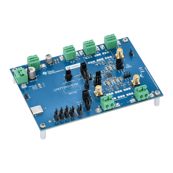
Figure 1-1. EVM Board Top View with Basic Connections and Default Jumpers........................................................................
Figure 4-1. GUI Front Page.........................................................................................................................................................
Figure 4-2. GUI Configuration Page............................................................................................................................................
Figure 4-3. GUI Register Map Page............................................................................................................................................
Figure 5-2. GUI Watchdog Validation Configuration..................................................................................................................
Configuration...................................................................................................................................11
Schematic......................................................................................................................................................12
Schematic...........................................................................................................................................13
Figure 6-3. MCU Schematic......................................................................................................................................................
SNVU851 - NOVEMBER 2023
Submit Document Feedback
ABSTRACT
Contact can cause burns.
Table of Contents
Connections..........................................................................................................................3
Requirements...................................................................................................4
GUI...............................................................................................................................8
List of Figures
Mode.........................................................................................................................10
Copyright © 2023 Texas Instruments Incorporated
CAUTION
Hot surface.
Do not touch!
Table of Contents
LP87725Q1EVM Evaluation Module
10
12
15
3
8
9
9
11
14
1
Advertisement
Table of Contents

Subscribe to Our Youtube Channel
Related Manuals for Texas Instruments LP87725Q1EVM


Summary of Contents for Texas Instruments LP87725Q1EVM
-
Page 1: Table Of Contents
The features of the device target safety-relevant applications with system-safety requirements up to ASIL-B level. This user's guide provides instructions to power-up and evaluate LP87725-Q1 device using the LP87725Q1EVM evaluation module (EVM) and software user interface (LP87725-Q1 GUI). By default LP87725Q1EVM has LP87725101RAGRQ1 device OTP version (17.6 MHz), but this EVM can also be used to evaluate another OTP... - Page 2 EVM...............................6 Table 4-1. Jumper Connections for Powering the EVM....................... Table 6-1. Bill of Materials................................16 Trademarks All trademarks are the property of their respective owners. LP87725Q1EVM Evaluation Module SNVU851 – NOVEMBER 2023 Submit Document Feedback Copyright © 2023 Texas Instruments Incorporated...
-
Page 3: Top View With Basic External Connections
Table 3-2 for the right jumper configuration for each power supply input. Figure 1-1. EVM Board Top View with Basic Connections and Default Jumpers SNVU851 – NOVEMBER 2023 LP87725Q1EVM Evaluation Module Submit Document Feedback Copyright © 2023 Texas Instruments Incorporated... -
Page 4: Input, Output Voltages, And Load Current Requirements
Make sure that PMIC junction temperature does not exceed 150 °C. 3 Jumpers and Connectors LP87725Q1EVM has many terminal blocks, jumpers and test points to offer certain flexibility to help users to verify the EVM according to their application conditions. However, the EVM is pre-configured with default jumper settings and users can power-up the regulators without the need of jumper modifications. -
Page 5: Table 3-2. Configuration Jumpers
GPIO signals connected to J14 which connects to PVIN_LS2/nINT/GPIO Pins 2 and 3 either MCU port directly or through level shifter depending on J14 jumper selection. SNVU851 – NOVEMBER 2023 LP87725Q1EVM Evaluation Module Submit Document Feedback Copyright © 2023 Texas Instruments Incorporated... -
Page 6: Test Points
SMA connector for BUCK3 noise measurement SMA connector for BUCK2 noise measurement SMA connector for BUCK1 noise measurement USB_5V_S Test point to measure 5 V supply from USB cable LP87725Q1EVM Evaluation Module SNVU851 – NOVEMBER 2023 Submit Document Feedback Copyright © 2023 Texas Instruments Incorporated... -
Page 7: Getting Started
GUI. 4.1 GUI Texas Instruments provides a simple to use LP87725-Q1 GUI tool to enable, configure, and evaluate the various features of the LP87725-Q1 device on the EVM. Please refer to the GUI README.md file in the GUI tool's Help->View README.md tab for a more detailed description of this tool. -
Page 8: Gui Installation And Working With Gui
CRC can be disabled by writing CONFIG_CRC_EN = 0h through Console window (Options → Show Console) or GUI Register Map Page. For example, output voltages, startup and shutdown delays and peak current limits can be changed for each buck converter. LP87725Q1EVM Evaluation Module SNVU851 – NOVEMBER 2023 Submit Document Feedback Copyright © 2023 Texas Instruments Incorporated... -
Page 9: Figure 4-2. Gui Configuration Page
Figure 4-2. GUI Configuration Page In the register map page shown in Figure 4-3, registers can be read or written to. Figure 4-3. GUI Register Map Page SNVU851 – NOVEMBER 2023 LP87725Q1EVM Evaluation Module Submit Document Feedback Copyright © 2023 Texas Instruments Incorporated... -
Page 10: Watchdog Configuration
Figure 5-3 . For further information on watchdog configuration, refer to the data sheet of LP87725-Q1 for watchdog section. LP87725Q1EVM Evaluation Module SNVU851 – NOVEMBER 2023 Submit Document Feedback Copyright © 2023 Texas Instruments Incorporated... -
Page 11: Figure 5-2. Gui Watchdog Validation Configuration
Watchdog Configuration Figure 5-2. GUI Watchdog Validation Configuration Figure 5-3. GUI Watchdog Configuration SNVU851 – NOVEMBER 2023 LP87725Q1EVM Evaluation Module Submit Document Feedback Copyright © 2023 Texas Instruments Incorporated... -
Page 12: Schematics, Layout And Bom
Schematics, Layout and BOM www.ti.com 6 Schematics, Layout and BOM This section contains the schematics, layout and the bill of materials for the LP87725Q1EVM. 6.1 Schematic Diagram This section includes images of the EVM schematics and different layers of the layout. -
Page 13: Figure 6-2. Preregulator Schematic
VCC_PIN: FPWM, SPSP ENPRE VBATPRE 1.00k VCCPRE RENT SYNCMODEPRE 255k SYNCCLKIN_MCU 1.00k VBATPRE 1.00k C104 RENB VBAT_PIN: FPWM, SSM enable 100k Figure 6-2. Preregulator Schematic SNVU851 – NOVEMBER 2023 LP87725Q1EVM Evaluation Module Submit Document Feedback Copyright © 2023 Texas Instruments Incorporated... -
Page 14: Figure 6-3. Mcu Schematic
6.3V nRSTOUT_LS nRSTOUT_MCU 2.2µF 2.2µF 6.3V 2.2µF 10µF 2.2µF TLV7103318QDSERQ1 MCUVCC TPS74533PQWDRVRQ1 blue 1.2k SN74GTL2003PWR 150mA Figure 6-3. MCU Schematic LP87725Q1EVM Evaluation Module SNVU851 – NOVEMBER 2023 Submit Document Feedback Copyright © 2023 Texas Instruments Incorporated... -
Page 15: Pcb Layer Diagram
Figure 6-7. Layout of Signal Layer 2, Layer 4 Figure 6-8. Layout of Ground Layer 2, Layer 5 Figure 6-9. Layout of Bottom Layer, Layer 6 SNVU851 – NOVEMBER 2023 LP87725Q1EVM Evaluation Module Submit Document Feedback Copyright © 2023 Texas Instruments Incorporated... -
Page 16: Bill Of Materials
C0603 22 pF X7R 30 ppm/°C 10.00% 50 V C0603C220K5RACAUTO KEMET C113 CAP, CERM, 1 uF, 25 V, +/- 10%, X7R, 0805 C0805C105K3RACTU Kemet LP87725Q1EVM Evaluation Module SNVU851 – NOVEMBER 2023 Submit Document Feedback Copyright © 2023 Texas Instruments Incorporated... - Page 17 RES, 1.00 k, 0.1%, 0.063 W, AEC-Q200 ERA-2APB102X Panasonic Grade 0, 0402 RES, 20.0 k, 1%, 0.1 W, AEC-Q200 Grade 0, CRCW060320K0FKEA Vishay-Dale 0603 SNVU851 – NOVEMBER 2023 LP87725Q1EVM Evaluation Module Submit Document Feedback Copyright © 2023 Texas Instruments Incorporated...
- Page 18 Texas Instruments channel comparator with 1-microsecond delay 14-TSSOP -40 to 125 Automotive 4 A Low Noise Synchronous Buck LM62440APPQRJRRQ1 Texas Instruments Regulators, RJR0014A (VQFN-HR-14) LP87725Q1EVM Evaluation Module SNVU851 – NOVEMBER 2023 Submit Document Feedback Copyright © 2023 Texas Instruments Incorporated...
- Page 19 R61, R63, R66, R68, RES, 10 k, 5%, 0.063 W, AEC-Q200 Grade 0, CRCW040210K0JNED Vishay-Dale 0402 R80, R82 RES, 1.00 k, 1%, 0.1 W, 0603 RC0603FR-071KL Yageo SNVU851 – NOVEMBER 2023 LP87725Q1EVM Evaluation Module Submit Document Feedback Copyright © 2023 Texas Instruments Incorporated...
- Page 20 STANDARD TERMS FOR EVALUATION MODULES Delivery: TI delivers TI evaluation boards, kits, or modules, including any accompanying demonstration software, components, and/or documentation which may be provided together or separately (collectively, an “EVM” or “EVMs”) to the User (“User”) in accordance with the terms set forth herein.
- Page 21 www.ti.com Regulatory Notices: 3.1 United States 3.1.1 Notice applicable to EVMs not FCC-Approved: FCC NOTICE: This kit is designed to allow product developers to evaluate electronic components, circuitry, or software associated with the kit to determine whether to incorporate such items in a finished product and software developers to write software applications for use with the end product.
- Page 22 www.ti.com Concernant les EVMs avec antennes détachables Conformément à la réglementation d'Industrie Canada, le présent émetteur radio peut fonctionner avec une antenne d'un type et d'un gain maximal (ou inférieur) approuvé pour l'émetteur par Industrie Canada. Dans le but de réduire les risques de brouillage radioélectrique à...
- Page 23 www.ti.com EVM Use Restrictions and Warnings: 4.1 EVMS ARE NOT FOR USE IN FUNCTIONAL SAFETY AND/OR SAFETY CRITICAL EVALUATIONS, INCLUDING BUT NOT LIMITED TO EVALUATIONS OF LIFE SUPPORT APPLICATIONS. 4.2 User must read and apply the user guide and other available documentation provided by TI regarding the EVM prior to handling or using the EVM, including without limitation any warning or restriction notices.
-
Page 24: Evm
Notwithstanding the foregoing, any judgment may be enforced in any United States or foreign court, and TI may seek injunctive relief in any United States or foreign court. Mailing Address: Texas Instruments, Post Office Box 655303, Dallas, Texas 75265 Copyright © 2023, Texas Instruments Incorporated... - Page 25 TI products. TI’s provision of these resources does not expand or otherwise alter TI’s applicable warranties or warranty disclaimers for TI products. TI objects to and rejects any additional or different terms you may have proposed. IMPORTANT NOTICE Mailing Address: Texas Instruments, Post Office Box 655303, Dallas, Texas 75265 Copyright © 2023, Texas Instruments Incorporated...
Need help?
Do you have a question about the LP87725Q1EVM and is the answer not in the manual?
Questions and answers