Advertisement
Quick Links
1
Introduction
The LP8557EVM evaluation kit is ready to be used with a power source and a PWM input. The boost
switching frequency and the maximum led current are set by resistors R3 and R4.
2
LP8557EVM Startup
The LP8557EVM requires a power source and Pulse Width Modulated (PWM) input. See
connector descriptions and the location of the PWM input on the left side of the board.
1. Connect the LED board to the LP8557 evaluation board. Set jumpers for 6 LEDs per string as shown
in
Figure
3.
2. Connect external power and ground to the board. Suggest 3.6V to VIN. VDD is not required if P2 is in
place.
3. Connect Ground to GND jack.
4. Connect a pulse generator or PWM source to the PWM input. R2 is a 10 KΩ resistor to ground on this
input.
5. Set pulse stream to 30 kHz frequency, 50% duty cycle, 3V input high level.
6. Turn on power supply.
7. Enable pulse stream output.
The LEDs will light at 50% brightness if a 50% duty cycle is used. The brightness will vary with the
positive duty cycle of the PWM input signal.
3
Changing Boost Frequency and PWM Frequency on the LP8557EVM
The LP8557EVM is configured to operate at 500 kHz boost switching frequency and 9.8 kHz PWM
frequency by the resistor R3 equal to zero ohms. This resistor can be changed to a value from Table 4 of
the LP8557 datasheet which is presented here.
Table 1. Setting Boost Switching and PWM Dimming Frequencies with an External Resistor
RFSET [Ω] (Tolerance)
470k - 1M (±5%)
300k, 330k (±5%)
200k (±5%)
147k, 150k, 154k, 158k (±1%)
121k (±1%)
100k (±1%)
86.6k (±1%)
75.0k (±1%)
63.4k (±1%)
52.3k, 53.6k (±1%)
44.2k, 45.3k (±1%)
39.2k (±1%)
34.0k (±1%)
30.1k (±1%)
SNVU285 – December 2013
Submit Documentation Feedback
ƒ
(kHz)
SW
500
500
500
500
500
500
500
500
1000
1000
1000
1000
1000
1000
Copyright © 2013, Texas Instruments Incorporated
SNVU285 – December 2013
LP8557EVM User Guide
ƒ
(kHz)
PWM
4.9
9.8
24.6
19.5
24.4
29.3
34.2
39.1
4.9
9.8
24.6
19.5
24.4
29.3
LP8557EVM User Guide
User's Guide
Figure 1
for the
1
Advertisement

Subscribe to Our Youtube Channel
Related Manuals for Texas Instruments LP8557EVM


Summary of Contents for Texas Instruments LP8557EVM
- Page 1 SNVU285 – December 2013 LP8557EVM User Guide Introduction The LP8557EVM evaluation kit is ready to be used with a power source and a PWM input. The boost switching frequency and the maximum led current are set by resistors R3 and R4. LP8557EVM Startup The LP8557EVM requires a power source and Pulse Width Modulated (PWM) input.
- Page 2 Changing Maximum Current on the LP8557EVM The LP8557EVM is configured to operate at a maximum current of 20 milliamps as set by resistor R4 equal to zero ohms. This resistor can be changed to a value from Table 6 of the LP8557 datasheet which is presented here.
-
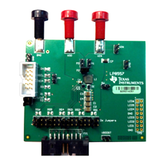
Page 3: Evm Description
EVM Description www.ti.com EVM Description The LP8557EVM kit includes the main evaluation board and an LED loadboard. Main EVM Board Figure 1. LP8557 EVM Main Board SNVU285 – December 2013 LP8557EVM User Guide Submit Documentation Feedback Copyright © 2013, Texas Instruments Incorporated... - Page 4 EVM Description www.ti.com Figure 2. Current Sense Resistors LED Loadboard Figure 3. LED Loadboard LP8557EVM User Guide SNVU285 – December 2013 Submit Documentation Feedback Copyright © 2013, Texas Instruments Incorporated...
-
Page 5: Kit Assembly
EVM Description www.ti.com Kit Assembly Figure 4. Kit Assembly SNVU285 – December 2013 LP8557EVM User Guide Submit Documentation Feedback Copyright © 2013, Texas Instruments Incorporated... - Page 6 Main EVM Schematic www.ti.com Main EVM Schematic Figure 5. LP8557 EVM Schematic LP8557EVM User Guide SNVU285 – December 2013 Submit Documentation Feedback Copyright © 2013, Texas Instruments Incorporated...
-
Page 7: Regulatory Compliance Information
Any exceptions to this are strictly prohibited and unauthorized by Texas Instruments unless user has obtained appropriate experimental/development licenses from local regulatory authorities, which is responsibility of user including its acceptable authorization. - Page 8 FCC Interference Statement for Class B EVM devices This equipment has been tested and found to comply with the limits for a Class B digital device, pursuant to part 15 of the FCC Rules. These limits are designed to provide reasonable protection against harmful interference in a residential installation. This equipment generates, uses and can radiate radio frequency energy and, if not installed and used in accordance with the instructions, may cause harmful interference to radio communications.
- Page 9 Also, please do not transfer this product, unless you give the same notice above to the transferee. Please note that if you could not follow the instructions above, you will be subject to penalties of Radio Law of Japan. Texas Instruments Japan Limited (address) 24-1, Nishi-Shinjuku 6 chome, Shinjuku-ku, Tokyo, Japan http://www.tij.co.jp...
- Page 10 FDA Class III or similar classification, then you must specifically notify TI of such intent and enter into a separate Assurance and Indemnity Agreement. Mailing Address: Texas Instruments, Post Office Box 655303, Dallas, Texas 75265 Copyright © 2013, Texas Instruments Incorporated...
-
Page 11: Important Notice
IMPORTANT NOTICE Texas Instruments Incorporated and its subsidiaries (TI) reserve the right to make corrections, enhancements, improvements and other changes to its semiconductor products and services per JESD46, latest issue, and to discontinue any product or service per JESD48, latest issue.
Need help?
Do you have a question about the LP8557EVM and is the answer not in the manual?
Questions and answers