Table of Contents
Advertisement
Quick Links
www.ti.com
User's Guide
LP877451Q1EVM Evaluation Module
The LP87745-Q1 device is designed to meet the power management requirements of the AWR and IWR MMICs
in various automotive and industrial radar applications. The device has three step-down DC/DC converters,
a 5 V boost converter and a 1.8 V/3.3 V LDO. The LDO is powered from the boost and intended for xWR
and peripheral devices IO supply. The device is controlled by an SPI serial interface and by enable signal.
The step-down DC/DC converters support programmable switching frequency of 17.6 MHz, 8.8 MHz or 4.4
MHz and have low noise across wide frequency range which enables LDO-free power solution with minimal
or no additional passive filtering. LP87745-Q1 device offers flexible external component selection to optimize
the solution in terms of performance or cost. The features of the device target safety-relevant applications with
system-safety requirements up to ASIL-C level.
This user's guide provides instructions to power up and evaluate LP87745-Q1 device using the
LP877451Q1EVM evaluation module (EVM) and software user interface (LP87745-Q1 GUI). By default
LP877451Q1EVM has LP877451A1RXVRQ1 device OTP version (17.6 MHz, Low noise use case BOM), but
this EVM can also be used to evaluate another OTP device from LP8774x-Q1 product family.
3 Jumpers and connectors.......................................................................................................................................................
Points..........................................................................................................................................................................6
Started........................................................................................................................................................................7
4.1
GUI.....................................................................................................................................................................................7
4.2 GUI Installation and working with GUI...............................................................................................................................
5
Watchdog...............................................................................................................................................................................10
6.1 Schematic Diagram..........................................................................................................................................................
6.2 PCB Layer Diagram.........................................................................................................................................................
6.3 Part List............................................................................................................................................................................
Figure 1-1. EVM Top-View Diagram With Basic Connections and Default Jumpers...................................................................
Figure 4-1. GUI Front Page.........................................................................................................................................................
Figure 4-2. GUI Configuration Page............................................................................................................................................
Figure 4-3. GUI Register Map Page............................................................................................................................................
Figure 6-1. PMIC Schematic......................................................................................................................................................
Schematic...........................................................................................................................................12
Figure 6-3. MCU Schematic......................................................................................................................................................
Figure 6-4. Layout of Top Layer, Layer 1...................................................................................................................................
SNVU769 - SEPTEMBER 2021
Submit Document Feedback
ABSTRACT
Table of Contents
Connections..........................................................................................................................2
Requirements...................................................................................................3
BOM..............................................................................................................................................11
List of Figures
Mode.........................................................................................................................10
2...........................................................................................................................14
3............................................................................................................................14
Copyright © 2021 Texas Instruments Incorporated
CAUTION
Hot surface.
Contact may cause burns.
Do not touch!
Table of Contents
4
7
11
14
15
2
8
8
9
11
13
14
1
Advertisement
Table of Contents

Related Manuals for Texas Instruments LP877451Q1EVM


Summary of Contents for Texas Instruments LP877451Q1EVM
-
Page 1: Table Of Contents
LP877451Q1EVM evaluation module (EVM) and software user interface (LP87745-Q1 GUI). By default LP877451Q1EVM has LP877451A1RXVRQ1 device OTP version (17.6 MHz, Low noise use case BOM), but this EVM can also be used to evaluate another OTP device from LP8774x-Q1 product family. -
Page 2: Top View With Basic External Connections
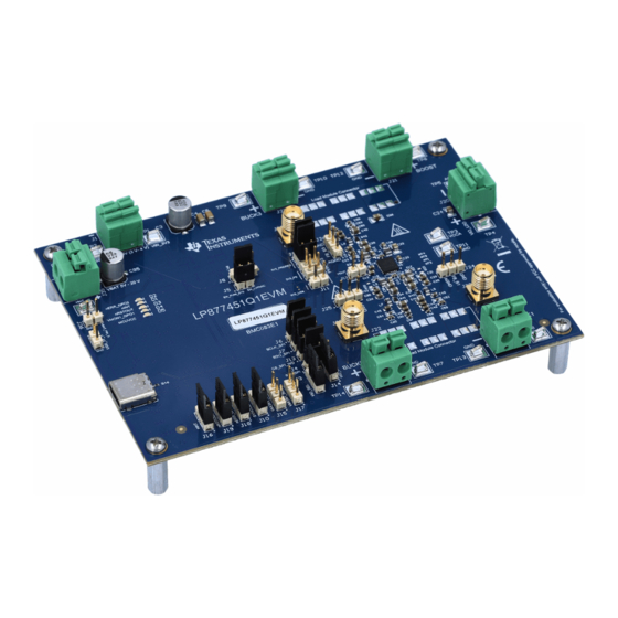
5V – 20V Nega ¢ Posi £ VIO_LDO VOUT BUCK1 VOUT Default Jumpers BUCK2 VOUT Figure 1-1. EVM Top-View Diagram With Basic Connections and Default Jumpers LP877451Q1EVM Evaluation Module SNVU769 – SEPTEMBER 2021 Submit Document Feedback Copyright © 2021 Texas Instruments Incorporated... -
Page 3: Input, Output Voltages, And Load Current Requirements
If all the regulators are loaded with maximum load current simultaneously, PMIC and PCB can become hot. Make sure that PMIC junction temperature does not exceed 150 °C. SNVU769 – SEPTEMBER 2021 LP877451Q1EVM Evaluation Module Submit Document Feedback Copyright © 2021 Texas Instruments Incorporated... -
Page 4: Jumpers And Connectors
3 Jumpers and connectors The LP877451Q1EVM has many terminal blocks, jumpers and test points to offer certain flexibility to help users to verify the EVM according to their application conditions. However, EVM is pre-configured with default jumper settings and users can power up the regulators without the need of jumper modifications. Setting these jumpers correctly for the correct function of the EVM is important. - Page 5 Connects PMIC nINT signal to nINT MCU port through level shifter Pins 2 and 3 (series resistors must be mounted if this option is used) SNVU769 – SEPTEMBER 2021 LP877451Q1EVM Evaluation Module Submit Document Feedback Copyright © 2021 Texas Instruments Incorporated...
-
Page 6: Test Points
SMA connector for BUCK3 noise measurement SMA connector for BUCK2 noise measurement SMA connector for BUCK1 noise measurement VBAT_PIN_S Test point to measure the VBAT input supply LP877451Q1EVM Evaluation Module SNVU769 – SEPTEMBER 2021 Submit Document Feedback Copyright © 2021 Texas Instruments Incorporated... -
Page 7: Getting Started
GUI. 4.1 GUI Texas Instruments provides a simple to use LP87745-Q1 GUI tool to enable, configure, and evaluate the various features of the LP87745-Q1 device on the EVM. Please refer to the GUI README.md file in the GUI tool's Help->View README.md tab for a more detailed description of this tool. -
Page 8: Figure 4-1. Gui Front Page
Figure 4-2. GUI Configuration Page In the register map page shown in Figure 4-3, registers can be read or written to. LP877451Q1EVM Evaluation Module SNVU769 – SEPTEMBER 2021 Submit Document Feedback Copyright © 2021 Texas Instruments Incorporated... -
Page 9: Figure 4-3. Gui Register Map Page
Getting Started Figure 4-3. GUI Register Map Page SNVU769 – SEPTEMBER 2021 LP877451Q1EVM Evaluation Module Submit Document Feedback Copyright © 2021 Texas Instruments Incorporated... -
Page 10: Watchdog
Generate a new question for the next watchdog sequence Q&A [n + 1] Q&A [n] Q&A [n + 1] Watchdog Sequence Figure 5-1. Watchdog Sequence in Q&A Mode LP877451Q1EVM Evaluation Module SNVU769 – SEPTEMBER 2021 Submit Document Feedback Copyright © 2021 Texas Instruments Incorporated... -
Page 11: Schematics, Layout And Bom
This section contains the schematics, layout and the bill of materials for the LP87745Q1EVM. 6.1 Schematic Diagram This section includes images of the EVM schematics and different layers of the layout. Figure 6-1. PMIC Schematic SNVU769 – SEPTEMBER 2021 LP877451Q1EVM Evaluation Module Submit Document Feedback Copyright © 2021 Texas Instruments Incorporated... -
Page 12: Figure 6-2. Preregulator Schematic
Schematics, Layout and BOM www.ti.com Figure 6-2. Preregulator Schematic LP877451Q1EVM Evaluation Module SNVU769 – SEPTEMBER 2021 Submit Document Feedback Copyright © 2021 Texas Instruments Incorporated... -
Page 13: Figure 6-3. Mcu Schematic
Schematics, Layout and BOM Figure 6-3. MCU Schematic SNVU769 – SEPTEMBER 2021 LP877451Q1EVM Evaluation Module Submit Document Feedback Copyright © 2021 Texas Instruments Incorporated... -
Page 14: Pcb Layer Diagram
Figure 6-7. Layout of Signal Layer 2, Layer 4 Figure 6-8. Layout of Ground Layer 2, Layer 5 Figure 6-9. Layout of Bottom Layer, Layer 6 LP877451Q1EVM Evaluation Module SNVU769 – SEPTEMBER 2021 Submit Document Feedback Copyright © 2021 Texas Instruments Incorporated... -
Page 15: Part List
CAP, Polymer Hybrid, 68 uF, 35 EEHZC1V680XP Panasonic V, +/- 20%, 35 ohm, 6.3x7.7 SMD C100 CAP, CERM, 1 uF, 50 V, +/- 10%, UMK107AB7105KA-T Taiyo Yuden X7R, 0603 SNVU769 – SEPTEMBER 2021 LP877451Q1EVM Evaluation Module Submit Document Feedback Copyright © 2021 Texas Instruments Incorporated... - Page 16 R2, R7, R77, R81, R86 RES, 100 k, 1%, 0.1 W, 0603 RC0603FR-07100KL Yageo RES, 0, 0%, 0.2 W, AEC-Q200 CRCW04020000Z0EDHP Vishay-Dale Grade 0, 0402 LP877451Q1EVM Evaluation Module SNVU769 – SEPTEMBER 2021 Submit Document Feedback Copyright © 2021 Texas Instruments Incorporated...
- Page 17 Boost for AWR and IWR Radar Sensors Linear Voltage Regulator IC 1 TPS74533PQWDRVRQ1 Texas Instruments Output 500mA 6-WSON (2x2) AEC-Q100 Quad Comparator, LM2901AVQPWRQ1 Texas Instruments PW0014A (TSSOP-14) SNVU769 – SEPTEMBER 2021 LP877451Q1EVM Evaluation Module Submit Document Feedback Copyright © 2021 Texas Instruments Incorporated...
- Page 18 Grade 0, 0603 RES, 0, 5%, 0.1 W, AEC-Q200 ERJ-2GE0R00X Panasonic Grade 0, 0402 R80, R83 RES, 1.00 k, 1%, 0.1 W, 0603 RC0603FR-071KL Yageo LP877451Q1EVM Evaluation Module SNVU769 – SEPTEMBER 2021 Submit Document Feedback Copyright © 2021 Texas Instruments Incorporated...
- Page 19 STANDARD TERMS FOR EVALUATION MODULES Delivery: TI delivers TI evaluation boards, kits, or modules, including any accompanying demonstration software, components, and/or documentation which may be provided together or separately (collectively, an “EVM” or “EVMs”) to the User (“User”) in accordance with the terms set forth herein.
- Page 20 www.ti.com Regulatory Notices: 3.1 United States 3.1.1 Notice applicable to EVMs not FCC-Approved: FCC NOTICE: This kit is designed to allow product developers to evaluate electronic components, circuitry, or software associated with the kit to determine whether to incorporate such items in a finished product and software developers to write software applications for use with the end product.
- Page 21 www.ti.com Concernant les EVMs avec antennes détachables Conformément à la réglementation d'Industrie Canada, le présent émetteur radio peut fonctionner avec une antenne d'un type et d'un gain maximal (ou inférieur) approuvé pour l'émetteur par Industrie Canada. Dans le but de réduire les risques de brouillage radioélectrique à...
- Page 22 www.ti.com EVM Use Restrictions and Warnings: 4.1 EVMS ARE NOT FOR USE IN FUNCTIONAL SAFETY AND/OR SAFETY CRITICAL EVALUATIONS, INCLUDING BUT NOT LIMITED TO EVALUATIONS OF LIFE SUPPORT APPLICATIONS. 4.2 User must read and apply the user guide and other available documentation provided by TI regarding the EVM prior to handling or using the EVM, including without limitation any warning or restriction notices.
-
Page 23: Evm
Notwithstanding the foregoing, any judgment may be enforced in any United States or foreign court, and TI may seek injunctive relief in any United States or foreign court. Mailing Address: Texas Instruments, Post Office Box 655303, Dallas, Texas 75265 Copyright © 2019, Texas Instruments Incorporated... - Page 24 TI products. TI’s provision of these resources does not expand or otherwise alter TI’s applicable warranties or warranty disclaimers for TI products.IMPORTANT NOTICE Mailing Address: Texas Instruments, Post Office Box 655303, Dallas, Texas 75265 Copyright © 2021, Texas Instruments Incorporated...
Need help?
Do you have a question about the LP877451Q1EVM and is the answer not in the manual?
Questions and answers