Table of Contents
Advertisement
Quick Links
The LP8756xQ1EVM (SV601325) Evaluation Module
This user's guide describes the operation of the SV601325 revision of the evaluation module for the
LP8756xQ1 multi-phase 4-core step-down converter from Texas Instruments (TI). If the board you have
has BMC031 in the upper-left corner, please reference
Module
document instead. The LP8756xQ1 can be used in five different output configurations, and this
user's guide includes all these five variants (see
information including the schematic and bill of materials (BOM).
......................................................................................................................
1
Overview
2
Quick Setup Guide
2.1
Installing/Opening the Software
2.2
Power Supply Setup
2.3
Notes on Efficiency Measurement Procedure
3
GUI Overview
3.1
Main Tab
3.2
Other Tabs and Menus
3.3
Console
4
Bill of Materials
5
Board Layout
6
LP8756xQ1EVM Schematics
1
LP8756xQ1EVM
2
LP8756 Installer License Agreement
3
Features of LP8756 Installation
4
LP8756 Destination Folder
5
LP8756 Installation Complete
6
Evaluation Software Graphical User Interface (GUI) When Board Connected
7
Assert nRST
8
Read Registers Buttons
9
BUCK0 Enabled
..................................................................................................................
10
Assert EN1
11
Accessing Direct Register Write
12
Direct Register Access View
13
Selecting Register Values
14
Register Update Mode
15
Config Tab of the LP8756 GUI
16
Advanced Tab of LP8756 GUI
SNVU472B – October 2016 – Revised August 2018
Submit Documentation Feedback
...........................................................................................................
..................................................................................
................................................................................................
...............................................................................................................
...........................................................................................................
...........................................................................................
.............................................................................................................
.............................................................................................................
................................................................................................................
.............................................................................................
.............................................................................................................
......................................................................................
............................................................................................
.................................................................................................
..............................................................................................
..................................................................................................................
.....................................................................................................
............................................................................................................
..........................................................................................
..............................................................................................
.................................................................................................
.....................................................................................................
...........................................................................................
...........................................................................................
Copyright © 2016–2018, Texas Instruments Incorporated
SNVU472B – October 2016 – Revised August 2018
The LP8756xQ1EVM (BMC031) Evaluation
Table
1). The user's guide also provides design
Contents
.................................................................
List of Figures
The LP8756xQ1EVM (SV601325) Evaluation Module
User's Guide
......................................
3
3
4
8
12
12
12
13
20
22
24
30
3
4
5
5
6
7
8
9
10
11
14
15
16
17
18
19
1
Advertisement
Table of Contents

Subscribe to Our Youtube Channel
Related Manuals for Texas Instruments LP8756 Q1EVM Series


Summary of Contents for Texas Instruments LP8756 Q1EVM Series
- Page 1 The LP8756xQ1EVM (SV601325) Evaluation Module This user’s guide describes the operation of the SV601325 revision of the evaluation module for the LP8756xQ1 multi-phase 4-core step-down converter from Texas Instruments (TI). If the board you have has BMC031 in the upper-left corner, please reference...
-
Page 2: Table Of Contents
Console Macros ..................Bill of Materials for LP8756xQ1EVM Trademarks All trademarks are the property of their respective owners. The LP8756xQ1EVM (SV601325) Evaluation Module SNVU472B – October 2016 – Revised August 2018 Submit Documentation Feedback Copyright © 2016–2018, Texas Instruments Incorporated... - Page 3 Upon opening the LP8756xQ1EVM package, ensure that the following items are included: • LP8756xQ1 Evaluation Board • USB Cable SNVU472B – October 2016 – Revised August 2018 The LP8756xQ1EVM (SV601325) Evaluation Module Submit Documentation Feedback Copyright © 2016–2018, Texas Instruments Incorporated...
- Page 4 Quick Setup Guide www.ti.com If any of the items are missing, contact the closest Texas Instruments Product Information Center to inquire about a replacement. Installing/Opening the Software The EVM software is controlled through a graphical user interface (GUI). The software communicates with the EVM through an available USB port.
- Page 5 Quick Setup Guide www.ti.com Figure 3. Features of LP8756 Installation Figure 4. LP8756 Destination Folder SNVU472B – October 2016 – Revised August 2018 The LP8756xQ1EVM (SV601325) Evaluation Module Submit Documentation Feedback Copyright © 2016–2018, Texas Instruments Incorporated...
- Page 6 Quick Setup Guide www.ti.com Figure 5. LP8756 Installation Complete The LP8756xQ1EVM (SV601325) Evaluation Module SNVU472B – October 2016 – Revised August 2018 Submit Documentation Feedback Copyright © 2016–2018, Texas Instruments Incorporated...
- Page 7 Quick Setup Guide www.ti.com Figure 6. Evaluation Software Graphical User Interface (GUI) When Board Connected SNVU472B – October 2016 – Revised August 2018 The LP8756xQ1EVM (SV601325) Evaluation Module Submit Documentation Feedback Copyright © 2016–2018, Texas Instruments Incorporated...
- Page 8 "Multiphase status" of Buck 0. Mode of other bucks are "Disabled" and Multiphase status is "Slave to Buck0". The EVM is now ready for testing with default register settings loaded. Figure 7. Assert nRST The LP8756xQ1EVM (SV601325) Evaluation Module SNVU472B – October 2016 – Revised August 2018 Submit Documentation Feedback Copyright © 2016–2018, Texas Instruments Incorporated...
- Page 9 Quick Setup Guide www.ti.com Figure 8. Read Registers Buttons SNVU472B – October 2016 – Revised August 2018 The LP8756xQ1EVM (SV601325) Evaluation Module Submit Documentation Feedback Copyright © 2016–2018, Texas Instruments Incorporated...
- Page 10 Quick Setup Guide www.ti.com Figure 9. BUCK0 Enabled The LP8756xQ1EVM (SV601325) Evaluation Module SNVU472B – October 2016 – Revised August 2018 Submit Documentation Feedback Copyright © 2016–2018, Texas Instruments Incorporated...
- Page 11 Quick Setup Guide www.ti.com Figure 10. Assert EN1 SNVU472B – October 2016 – Revised August 2018 The LP8756xQ1EVM (SV601325) Evaluation Module Submit Documentation Feedback Copyright © 2016–2018, Texas Instruments Incorporated...
- Page 12 GUI, and then enable buck regulator(s) by ENx pin or EN_BUCKx bit. The LP8756xQ1EVM (SV601325) Evaluation Module SNVU472B – October 2016 – Revised August 2018 Submit Documentation Feedback Copyright © 2016–2018, Texas Instruments Incorporated...
- Page 13 When using direct register access, TI recommends un-checking the poll status check-box. This way the GUI will only do the reads and writes commanded from the direct access dialog. SNVU472B – October 2016 – Revised August 2018 The LP8756xQ1EVM (SV601325) Evaluation Module Submit Documentation Feedback Copyright © 2016–2018, Texas Instruments Incorporated...
- Page 14 GUI Overview www.ti.com Figure 11. Accessing Direct Register Write The LP8756xQ1EVM (SV601325) Evaluation Module SNVU472B – October 2016 – Revised August 2018 Submit Documentation Feedback Copyright © 2016–2018, Texas Instruments Incorporated...
- Page 15 GUI Overview www.ti.com Figure 12. Direct Register Access View SNVU472B – October 2016 – Revised August 2018 The LP8756xQ1EVM (SV601325) Evaluation Module Submit Documentation Feedback Copyright © 2016–2018, Texas Instruments Incorporated...
- Page 16 GUI Overview www.ti.com Figure 13. Selecting Register Values The LP8756xQ1EVM (SV601325) Evaluation Module SNVU472B – October 2016 – Revised August 2018 Submit Documentation Feedback Copyright © 2016–2018, Texas Instruments Incorporated...
- Page 17 LP8756xQ1 data sheet for explanation of the functions. See following images for reference of the Config and Advanced tabs. SNVU472B – October 2016 – Revised August 2018 The LP8756xQ1EVM (SV601325) Evaluation Module Submit Documentation Feedback Copyright © 2016–2018, Texas Instruments Incorporated...
- Page 18 GUI Overview www.ti.com Figure 15. Config Tab of the LP8756 GUI The LP8756xQ1EVM (SV601325) Evaluation Module SNVU472B – October 2016 – Revised August 2018 Submit Documentation Feedback Copyright © 2016–2018, Texas Instruments Incorporated...
- Page 19 GUI Overview www.ti.com Figure 16. Advanced Tab of LP8756 GUI SNVU472B – October 2016 – Revised August 2018 The LP8756xQ1EVM (SV601325) Evaluation Module Submit Documentation Feedback Copyright © 2016–2018, Texas Instruments Incorporated...
-
Page 20: Opening Console
18. The console has a number of integrated macros that are listed in Table Figure 17. Opening Console The LP8756xQ1EVM (SV601325) Evaluation Module SNVU472B – October 2016 – Revised August 2018 Submit Documentation Feedback Copyright © 2016–2018, Texas Instruments Incorporated... -
Page 21: Example Of Command Use In Console
SNVU472B – October 2016 – Revised August 2018 The LP8756xQ1EVM (SV601325) Evaluation Module Submit Documentation Feedback Copyright © 2016–2018, Texas Instruments Incorporated... - Page 22 Machine Screw, Round, #4-40 x 1/4, H1, H2, H3, H4 NY PMS 440 0025 PH Nylon, Philips panhead The LP8756xQ1EVM (SV601325) Evaluation Module SNVU472B – October 2016 – Revised August 2018 Submit Documentation Feedback Copyright © 2016–2018, Texas Instruments Incorporated...
- Page 23 Products Standard Surface Mount Shield , 26.21 x Laird-Signal Integrity H11, H12 BMI-S-203-F 26.21 mm, Height 5.08mm Products SNVU472B – October 2016 – Revised August 2018 The LP8756xQ1EVM (SV601325) Evaluation Module Submit Documentation Feedback Copyright © 2016–2018, Texas Instruments Incorporated...
- Page 24 EMI reduction. With these modifications, the EVMs can pass CISPR25 radiated and conducted EMI test without (optional) EMI shields H5 and H6. The LP8756xQ1EVM (SV601325) Evaluation Module SNVU472B – October 2016 – Revised August 2018 Submit Documentation Feedback Copyright © 2016–2018, Texas Instruments Incorporated...
-
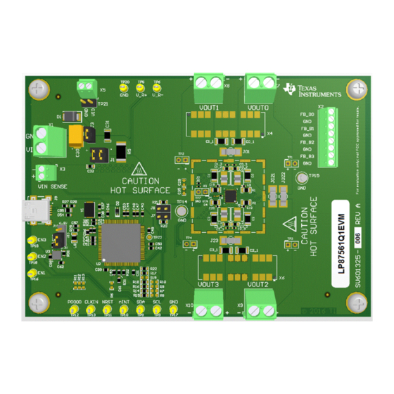
Page 25: Top View Of The Lp8756Xq1Evm
Board Layout www.ti.com Figure 20. Top View of the LP8756xQ1EVM Figure 21. Component Placement Top Layer SNVU472B – October 2016 – Revised August 2018 The LP8756xQ1EVM (SV601325) Evaluation Module Submit Documentation Feedback Copyright © 2016–2018, Texas Instruments Incorporated... -
Page 26: Component Placement Bottom Layer
SW node size and EMI. Also snubber circuits are placed next to SW nets for EMI reduction. Multiple GND vias are used to provide solid ground around the LP8756xQ1 device. Figure 23. Top Layer The LP8756xQ1EVM (SV601325) Evaluation Module SNVU472B – October 2016 – Revised August 2018 Submit Documentation Feedback Copyright © 2016–2018, Texas Instruments Incorporated... -
Page 27: Mid-Layer1
VIN supply is routed in this layer between the ground planes to reduce radiated emissions. VIN and GND vias are placed in hatched pattern to avoid large gaps in these planes. Figure 25. Mid-Layer2 SNVU472B – October 2016 – Revised August 2018 The LP8756xQ1EVM (SV601325) Evaluation Module Submit Documentation Feedback Copyright © 2016–2018, Texas Instruments Incorporated... -
Page 28: Mid-Layer3
Figure 26. Mid-Layer3 Placed close to bottom layer (0.063 mm) to reduce parasitic inductance. Figure 27. Mid-Layer4, GND Plane The LP8756xQ1EVM (SV601325) Evaluation Module SNVU472B – October 2016 – Revised August 2018 Submit Documentation Feedback Copyright © 2016–2018, Texas Instruments Incorporated... -
Page 29: Bottom Layer (Note Mirror View)
Input capacitors and filters are placed under the LP8756xQ1 into bottom layer. This allows closer placement of the inductors and input components reducing SW and VIN net areas and improving EMI. Figure 28. Bottom Layer (note mirror view) SNVU472B – October 2016 – Revised August 2018 The LP8756xQ1EVM (SV601325) Evaluation Module Submit Documentation Feedback Copyright © 2016–2018, Texas Instruments Incorporated... -
Page 30: Lp87561Q1Evm Schematic
22µF 3300pF 0.1µF AGND AGND 0.1µF AGND LP87561DRNFRQ1 Copyright © 2016, Texas Instruments Incorporated Figure 29. LP87561Q1EVM Schematic The LP8756xQ1EVM (SV601325) Evaluation Module SNVU472B – October 2016 – Revised August 2018 Submit Documentation Feedback Copyright © 2016–2018, Texas Instruments Incorporated... -
Page 31: Lp87562Q1Evm Schematic
22µF 3300pF 0.1µF AGND AGND 0.1µF AGND LP87562ARNFRQ1 Copyright © 2016, Texas Instruments Incorporated Figure 30. LP87562Q1EVM Schematic SNVU472B – October 2016 – Revised August 2018 The LP8756xQ1EVM (SV601325) Evaluation Module Submit Documentation Feedback Copyright © 2016–2018, Texas Instruments Incorporated... - Page 32 22µF 22µF 3300pF 0.1µF AGND AGND 0.1µF AGND LP87563BRNFRQ1 Copyright © 2016, Texas Instruments Incorporated Figure 31. LP87563Q1EVM The LP8756xQ1EVM (SV601325) Evaluation Module SNVU472B – October 2016 – Revised August 2018 Submit Documentation Feedback Copyright © 2016–2018, Texas Instruments Incorporated...
-
Page 33: Lp87564Q1Evm Schematic
22µF 3300pF 0.1µF AGND AGND 0.1µF AGND LP87564FRNFRQ1 Copyright © 2016, Texas Instruments Incorporated Figure 32. LP87564Q1EVM Schematic SNVU472B – October 2016 – Revised August 2018 The LP8756xQ1EVM (SV601325) Evaluation Module Submit Documentation Feedback Copyright © 2016–2018, Texas Instruments Incorporated... -
Page 34: Lp87565Q1Evm Schematic
22µF 3300pF 0.1µF AGND AGND 0.1µF AGND LP87565ARNFRQ1 Copyright © 2016, Texas Instruments Incorporated Figure 33. LP87565Q1EVM Schematic The LP8756xQ1EVM (SV601325) Evaluation Module SNVU472B – October 2016 – Revised August 2018 Submit Documentation Feedback Copyright © 2016–2018, Texas Instruments Incorporated... -
Page 35: Evm Connectors
TP17 TP18 VOUT1 VOUT3 TP19 1715721 1715721 TP20 Copyright © 2016, Texas Instruments Incorporated Figure 34. EVM Connectors SNVU472B – October 2016 – Revised August 2018 The LP8756xQ1EVM (SV601325) Evaluation Module Submit Documentation Feedback Copyright © 2016–2018, Texas Instruments Incorporated... - Page 36 1734035-2 1.00k 1.00k 1µF 0.01µF LP3996SD-1833/NOPB Copyright © 2016, Texas Instruments Incorporated Figure 35. EVM I C Interface The LP8756xQ1EVM (SV601325) Evaluation Module SNVU472B – October 2016 – Revised August 2018 Submit Documentation Feedback Copyright © 2016–2018, Texas Instruments Incorporated...
-
Page 37: Snvu472B - October 2016 - Revised August 2018
Added (SV601325) to the title to indicate which EVM version it applies to ................. • Added link to the newer BMC031 version of this document ....................• Added hyperlink for the GUI installer SNVU472B – October 2016 – Revised August 2018 Revision History Submit Documentation Feedback Copyright © 2016–2018, Texas Instruments Incorporated... - Page 38 STANDARD TERMS FOR EVALUATION MODULES Delivery: TI delivers TI evaluation boards, kits, or modules, including any accompanying demonstration software, components, and/or documentation which may be provided together or separately (collectively, an “EVM” or “EVMs”) to the User (“User”) in accordance with the terms set forth herein.
- Page 39 FCC Interference Statement for Class B EVM devices NOTE: This equipment has been tested and found to comply with the limits for a Class B digital device, pursuant to part 15 of the FCC Rules. These limits are designed to provide reasonable protection against harmful interference in a residential installation.
- Page 40 【無線電波を送信する製品の開発キットをお使いになる際の注意事項】 開発キットの中には技術基準適合証明を受けて いないものがあります。 技術適合証明を受けていないもののご使用に際しては、電波法遵守のため、以下のいずれかの 措置を取っていただく必要がありますのでご注意ください。 1. 電波法施行規則第6条第1項第1号に基づく平成18年3月28日総務省告示第173号で定められた電波暗室等の試験設備でご使用 いただく。 2. 実験局の免許を取得後ご使用いただく。 3. 技術基準適合証明を取得後ご使用いただく。 なお、本製品は、上記の「ご使用にあたっての注意」を譲渡先、移転先に通知しない限り、譲渡、移転できないものとします。 上記を遵守頂けない場合は、電波法の罰則が適用される可能性があることをご留意ください。 日本テキサス・イ ンスツルメンツ株式会社 東京都新宿区西新宿6丁目24番1号 西新宿三井ビル 3.3.3 Notice for EVMs for Power Line Communication: Please see http://www.tij.co.jp/lsds/ti_ja/general/eStore/notice_02.page 電力線搬送波通信についての開発キットをお使いになる際の注意事項については、次のところをご覧ください。http:/ /www.tij.co.jp/lsds/ti_ja/general/eStore/notice_02.page 3.4 European Union 3.4.1 For EVMs subject to EU Directive 2014/30/EU (Electromagnetic Compatibility Directive): This is a class A product intended for use in environments other than domestic environments that are connected to a low-voltage power-supply network that supplies buildings used for domestic purposes.
- Page 41 Notwithstanding the foregoing, any judgment may be enforced in any United States or foreign court, and TI may seek injunctive relief in any United States or foreign court. Mailing Address: Texas Instruments, Post Office Box 655303, Dallas, Texas 75265 Copyright © 2018, Texas Instruments Incorporated...
- Page 42 IMPORTANT NOTICE FOR TI DESIGN INFORMATION AND RESOURCES Texas Instruments Incorporated (‘TI”) technical, application or other design advice, services or information, including, but not limited to, reference designs and materials relating to evaluation modules, (collectively, “TI Resources”) are intended to assist designers who are developing applications that incorporate TI products;...
Need help?
Do you have a question about the LP8756 Q1EVM Series and is the answer not in the manual?
Questions and answers