
Subscribe to Our Youtube Channel
Related Manuals for Texas Instruments LP8860-Q1EVM


Summary of Contents for Texas Instruments LP8860-Q1EVM
- Page 1 Using the LP8860-Q1EVM Evaluation Module User's Guide Literature Number: SNVU382A April 2014 – Revised June 2014...
-
Page 2: Table Of Contents
Changing Boost Switching Frequency to 2.2 MHz ..........Cluster Mode, 4 LED Strings with Independent Brightness Control .............. Using EVM without MCU (MSP430), Standalone Mode .......................... Revision History Contents SNVU382A – April 2014 – Revised June 2014 Submit Documentation Feedback Copyright © 2014, Texas Instruments Incorporated... - Page 3 C-4. Forward Voltage for Cree Xlamp ML-B LEDs ......................D-1. Jumper Positions ......................D-2. CPUMP Jumper ......................D-3. Interface Jumpers SNVU382A – April 2014 – Revised June 2014 List of Figures Submit Documentation Feedback Copyright © 2014, Texas Instruments Incorporated...
- Page 4 List of Figures SNVU382A – April 2014 – Revised June 2014 Submit Documentation Feedback Copyright © 2014, Texas Instruments Incorporated...
-
Page 5: Preface
If You Need Assistance Contact your local TI sales representative. SNVU382A – April 2014 – Revised June 2014 Read This First Submit Documentation Feedback Copyright © 2014, Texas Instruments Incorporated... -
Page 6: Introduction
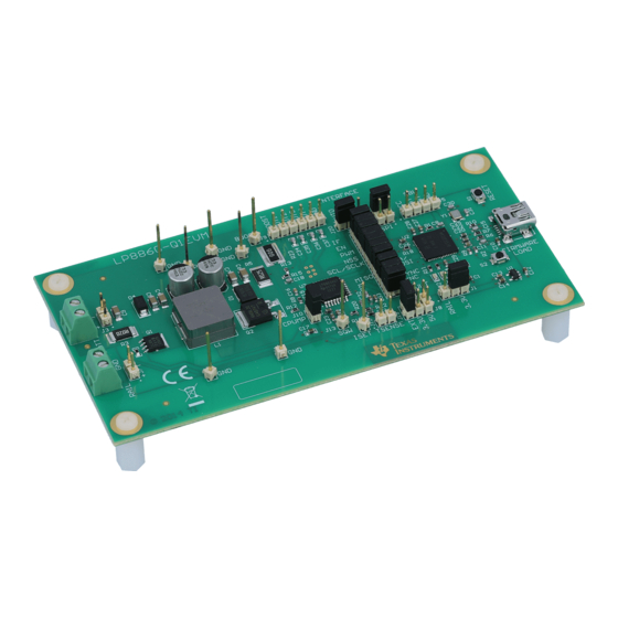
The Texas Instruments LP8860-Q1EVM evaluation module (EVM) helps designers evaluate the operation and performance of the LP8860-Q1 device. The LP8860-Q1EVM uses the LP8860-Q1 to drive up to 4 LED strings for LCD backlighting with high efficiency. Information about output voltage and current ratings... -
Page 7: Description Of The Lp8860-Q1
Extensive Safety and Fault Tolerance Features • SPI or I C Interface Applications • Automotive Infotainment, Instrument Cluster and Backlighting Systems SNVU382A – April 2014 – Revised June 2014 Description of the LP8860-Q1 Submit Documentation Feedback Copyright © 2014, Texas Instruments Incorporated... -
Page 8: Typical Applications
SGND LGND PGND Figure 2-1. Typical Application, Simple PWM Control, VDD = 3.3 V, Charge Pump On, 4 Strings Description of the LP8860-Q1 SNVU382A – April 2014 – Revised June 2014 Submit Documentation Feedback Copyright © 2014, Texas Instruments Incorporated... -
Page 9: Typical Application, Spi Control, Vdd = 5 V, Charge Pump Off, 2 Strings
FAULT SGND LGND PGND Figure 2-2. Typical Application, SPI Control, VDD = 5 V, Charge Pump Off, 2 Strings SNVU382A – April 2014 – Revised June 2014 Description of the LP8860-Q1 Submit Documentation Feedback Copyright © 2014, Texas Instruments Incorporated... -
Page 10: Typical Application, I
SGND LGND PGND Figure 2-3. Typical Application, I C Control, VDD = 3.3 V, Charge Pump On, 4 Strings Description of the LP8860-Q1 SNVU382A – April 2014 – Revised June 2014 Submit Documentation Feedback Copyright © 2014, Texas Instruments Incorporated... -
Page 11: Typical Application, Without Serial Interface, Vdd = 5 V, Charge Pump Off, 3 Strings
SGND LGND PGND Figure 2-4. Typical Application, without Serial Interface, VDD = 5 V, Charge Pump Off, 3 Strings SNVU382A – April 2014 – Revised June 2014 Description of the LP8860-Q1 Submit Documentation Feedback Copyright © 2014, Texas Instruments Incorporated... -
Page 12: Hardware Setup
(same as VDD or 3.3V) Figure 3-1. Evaluation Board Connectors and Setup Note. If charge pump is not in use, J10 “CPUMP” should be shorted. Hardware Setup SNVU382A – April 2014 – Revised June 2014 Submit Documentation Feedback Copyright © 2014, Texas Instruments Incorporated... -
Page 13: Board Layout
Chapter 4 SNVU382A – April 2014 – Revised June 2014 Board Layout Figure 4-1. Top Layer Figure 4-2. Bottom Layer (GND) SNVU382A – April 2014 – Revised June 2014 Board Layout Submit Documentation Feedback Copyright © 2014, Texas Instruments Incorporated... -
Page 14: Pcb Layout Example
VSENSE_P VDDIO/EN ISET TSENSE VIA to GND plane Figure 4-3. PCB Layout Example See the LP8860-Q1 datasheet for PCB layout guidelines. Board Layout SNVU382A – April 2014 – Revised June 2014 Submit Documentation Feedback Copyright © 2014, Texas Instruments Incorporated... -
Page 15: Board Stackup
Top layer - copper 35 µm • Core 1.6 mm • Bottom Layer - copper 35 µm • Surface finish immersion gold SNVU382A – April 2014 – Revised June 2014 Board Stackup Submit Documentation Feedback Copyright © 2014, Texas Instruments Incorporated... -
Page 16: Power Sequences
The backlight is shut down either with setting PWM input low or by writing zero brightness value to registers, depending on the brightness control mode and phase shift configuration. See the LP8860-Q1 datasheet for details. Power Sequences SNVU382A – April 2014 – Revised June 2014 Submit Documentation Feedback Copyright © 2014, Texas Instruments Incorporated... -
Page 17: Evaluation Board Schematic
SNVU382A – April 2014 – Revised June 2014 Evaluation Board Schematic Figure 7-1. Evaluation Board Schematic, Microcontroller and Related Components SNVU382A – April 2014 – Revised June 2014 Evaluation Board Schematic Submit Documentation Feedback Copyright © 2014, Texas Instruments Incorporated... -
Page 18: Evaluation Board Schematic, Lp8860-Q1 And Main Components
Figure 7-2. Evaluation Board Schematic, LP8860-Q1 and Main Components Evaluation Board Schematic SNVU382A – April 2014 – Revised June 2014 Submit Documentation Feedback Copyright © 2014, Texas Instruments Incorporated... -
Page 19: Bill Of Materials
Chapter 8 SNVU382A – April 2014 – Revised June 2014 Bill of Materials The following is the bill of materials for the LP8860-Q1EVM: Designator Description Manufacturer Part Number C1, C10, C12, C14, CAP, CERM, 10uF, 16V, +/-20%, Taiyo Yuden EMK107BBJ106MA-T... - Page 20 LOW EMI, High Performance 4- Texas Instruments LP8860QVFPRQ1 Channel LED Driver for Automotive Lighting, VFP0032B Crystal, 24.000MHz, 18pF, SMD Abracon Corportation ABM8-24.000MHZ-B2-T Bill of Materials SNVU382A – April 2014 – Revised June 2014 Submit Documentation Feedback Copyright © 2014, Texas Instruments Incorporated...
-
Page 21: Evaluation Software
Evaluation software is available for download from the TI web site. The LP8860-Q1EVM is connected via USB to the computer and controlled with special evaluation software (Windows). An MSP430 microcontroller is used with the EVM to provide easy I C/SPI communication, external PWM, boost SYNC and VSYNC control, VDDIO/EN, IF, and FAULT pins control with the LP8860-Q1 via USB. -
Page 22: Main Window Structure
± pin control or protocol USB VCP number USB state Command GUI compilation Registers bit Firmware compilation date controls date Figure 9-1. Main Window Structure Evaluation Software SNVU382A – April 2014 – Revised June 2014 Submit Documentation Feedback Copyright © 2014, Texas Instruments Incorporated... -
Page 23: Pin Control Tab
C/SPI) can be set, VDDIO/EN control enables/disables the device. Frequency generators – PWM for brightness control, SYNC for boost and VSYNC for LED output PWM synchronization are in this tab. SNVU382A – April 2014 – Revised June 2014 Evaluation Software Submit Documentation Feedback Copyright © 2014, Texas Instruments Incorporated... -
Page 24: Brightness Control Tab
Additional controls are functional when one or more outputs are in cluster mode. Please refer to the LP8860-Q1 datasheet for details. Figure 9-3. Brightness Control Tab Evaluation Software SNVU382A – April 2014 – Revised June 2014 Submit Documentation Feedback Copyright © 2014, Texas Instruments Incorporated... -
Page 25: Faults And Status Tab
Temperature and output current/PWM reading are available from this tab as well. Output PWM and current reading can help to understand better Hybrid PWM and Current dimming functionality. Figure 9-4. Fault and Status Tab SNVU382A – April 2014 – Revised June 2014 Evaluation Software Submit Documentation Feedback Copyright © 2014, Texas Instruments Incorporated... -
Page 26: Boost Tab
Figure 9-6. Interactive Boost Diagram Window Evaluation Software SNVU382A – April 2014 – Revised June 2014 Submit Documentation Feedback Copyright © 2014, Texas Instruments Incorporated... -
Page 27: Fault And Adaptive Voltage Control Tab
9-8. This window explains LED fault and adaptive boost control functionality: Figure 9-8. LED Fault And Adaptive Voltage Control Functionality Diagram SNVU382A – April 2014 – Revised June 2014 Evaluation Software Submit Documentation Feedback Copyright © 2014, Texas Instruments Incorporated... -
Page 28: Led Drivers Tab
9-12) or internal oscillator (Figure 9-13 ) is available by clicking the PWM/PLL Calculator button. Figure 9-10. LED Driver Diagram Window Evaluation Software SNVU382A – April 2014 – Revised June 2014 Submit Documentation Feedback Copyright © 2014, Texas Instruments Incorporated... -
Page 29: Pll Diagram Window
Figure 9-11. PLL Diagram Window STEP2 STEP1 STEP4 STEP3 Figure 9-12. PLL Calculator for External VSYNC (Steps Show Order for Applying Commands) SNVU382A – April 2014 – Revised June 2014 Evaluation Software Submit Documentation Feedback Copyright © 2014, Texas Instruments Incorporated... -
Page 30: Pll Calculator For Internal Oscillator
Usage www.ti.com Figure 9-13. PLL Calculator for Internal Oscillator Evaluation Software SNVU382A – April 2014 – Revised June 2014 Submit Documentation Feedback Copyright © 2014, Texas Instruments Incorporated... -
Page 31: Temperature Tab
LED temperature control mode, and current dimming with external temperature sensor. Figure 9-14. Temperature Sensors Control SNVU382A – April 2014 – Revised June 2014 Evaluation Software Submit Documentation Feedback Copyright © 2014, Texas Instruments Incorporated... -
Page 32: Eeprom Map Tab
9-15) the user can see actual value of EEPROM registers bit and control bits directly by writing or reading bytes (buttons W and R on the right side). Figure 9-15. EEPROM Map Evaluation Software SNVU382A – April 2014 – Revised June 2014 Submit Documentation Feedback Copyright © 2014, Texas Instruments Incorporated... -
Page 33: History Tab
C/SPI writes used to configure/control the LP8860-Q1 device. This can be used as a reference for developing software for real application. Figure 9-16. History Tab SNVU382A – April 2014 – Revised June 2014 Evaluation Software Submit Documentation Feedback Copyright © 2014, Texas Instruments Incorporated... -
Page 34: A Virtual Com Port Configuration
Administrator rights to make the changes. Figure A-1. Device Manager View. Select the Virtual COM Port Virtual COM Port Configuration SNVU382A – April 2014 – Revised June 2014 Submit Documentation Feedback Copyright © 2014, Texas Instruments Incorporated... -
Page 35: Open Properties By Clicking Right Mouse Button On Virtual Com Port
Figure A-2. Open Properties by Clicking Right Mouse Button on Virtual COM Port Figure A-3. Select Port Settings from the Virtual COM Port Properties SNVU382A – April 2014 – Revised June 2014 Virtual COM Port Configuration Submit Documentation Feedback Copyright © 2014, Texas Instruments Incorporated... -
Page 36: Select Advanced From Virtual Com Port Properties And Select Com Port Number (9 Or Smaller)
Appendix A www.ti.com Figure A-4. Select Advanced from Virtual COM Port Properties and Select COM Port Number (9 or smaller) Virtual COM Port Configuration SNVU382A – April 2014 – Revised June 2014 Submit Documentation Feedback Copyright © 2014, Texas Instruments Incorporated... -
Page 37: B Virtual Com Port Communication
Reset bit 0 port 01 S0101 S1234 Set masked bits, 12 - port number, 34 - mask OK<0x0A> Set bit 0 port 01 SNVU382A – April 2014 – Revised June 2014 Virtual COM Port Communication Submit Documentation Feedback Copyright © 2014, Texas Instruments Incorporated... -
Page 38: Led Load Board
NOTE: The LED board is not included with the EVM -- contact your local TI sales representative if board is needed. Figure C-1. LED Load Board - Top Side Figure C-2. LED Load Board - Bottom View LED Load Board SNVU382A – April 2014 – Revised June 2014 Submit Documentation Feedback Copyright © 2014, Texas Instruments Incorporated... -
Page 39: Led Load Board - Schematic Diagram
D100 D120 J105 J126 J106 J127 10.0 10.0 10.0 10.0 10.0 10.0 Figure C-3. LED Load Board - Schematic Diagram SNVU382A – April 2014 – Revised June 2014 LED Load Board Submit Documentation Feedback Copyright © 2014, Texas Instruments Incorporated... -
Page 40: Forward Voltage For Cree Xlamp Ml-B Leds
Samtec TSW-107-07-G-S Cool White SMD LED XLamp D1...D120 Cree MLBAWT-A1-0000-000W51 mL-B Figure C-4. Forward Voltage for Cree Xlamp ML-B LEDs LED Load Board SNVU382A – April 2014 – Revised June 2014 Submit Documentation Feedback Copyright © 2014, Texas Instruments Incorporated... -
Page 41: D Quick Start Guide
LED load board with EVM is used. Some examples refer to eep-files (example: default EEPROM 300kHz.eep). These files are provided as part of the LP8860-Q1EVM software which can be downloaded from the LP8860-Q1 tools folder on the Texas Instruments website. - Page 42 NOTE: Keep jumper J1 at a 3.3-V setting to ensure safe operation regardless of RAIL value (MSP430 doesn't tolerate a 5-V input or output voltage). Quick Start Guide SNVU382A – April 2014 – Revised June 2014 Submit Documentation Feedback Copyright © 2014, Texas Instruments Incorporated...
-
Page 43: Jumper Positions
EVM Board Default Jumper and Cable Positions www.ti.com Figure D-1. Jumper Positions SNVU382A – April 2014 – Revised June 2014 Quick Start Guide Submit Documentation Feedback Copyright © 2014, Texas Instruments Incorporated... -
Page 44: Cpump Jumper
EVM Board Default Jumper and Cable Positions www.ti.com If charge pump is disabled, jumper J10 CPUMP should be shorted Figure D-2. CPUMP Jumper Quick Start Guide SNVU382A – April 2014 – Revised June 2014 Submit Documentation Feedback Copyright © 2014, Texas Instruments Incorporated... - Page 45 EVM Board Default Jumper and Cable Positions www.ti.com SNVU382A – April 2014 – Revised June 2014 Quick Start Guide Submit Documentation Feedback Copyright © 2014, Texas Instruments Incorporated...
-
Page 46: First Step: Light Up Leds
Not mandatory – check register content, Read registers. This will read the register contents of the LP8860-Q1 and make sure GUI reflects the register state. Quick Start Guide SNVU382A – April 2014 – Revised June 2014 Submit Documentation Feedback Copyright © 2014, Texas Instruments Incorporated... - Page 47 Set LED brightness (%) using the Display/Cluster 1 control. Default mode (default EEPROM) is set to Display mode. SNVU382A – April 2014 – Revised June 2014 Quick Start Guide Submit Documentation Feedback Copyright © 2014, Texas Instruments Incorporated...
-
Page 48: Changing Eeprom Parameters
4. Change parameter. 5. If user wants to save new setting in EEPROM – Burn EEPROM. After EEPROM burning toggle VDDIO/EN. Quick Start Guide SNVU382A – April 2014 – Revised June 2014 Submit Documentation Feedback Copyright © 2014, Texas Instruments Incorporated... -
Page 49: Recovering Original Eeprom Parameters
1. Make sure LED brightness is 0%. Also check that PLL is disabled in LED drivers tab. 2. Unlock EEPROM, if it is not done already. 3. Load EEPROM setup file, “default EEPROM 300kHz.eep”. SNVU382A – April 2014 – Revised June 2014 Quick Start Guide Submit Documentation Feedback Copyright © 2014, Texas Instruments Incorporated... - Page 50 Recovering Original EEPROM Parameters www.ti.com 4. Burn EEPROM. 5. Toggle VDDIO/EN to restart the LP8860-Q1. Quick Start Guide SNVU382A – April 2014 – Revised June 2014 Submit Documentation Feedback Copyright © 2014, Texas Instruments Incorporated...
-
Page 51: C/Spi Register Control To Pwm Input Pin Control
Set PWM input duty cycle Duty, % , press Update to activate PWM. Another option is to use sliding control. LEDs will turn light on. SNVU382A – April 2014 – Revised June 2014 Quick Start Guide Submit Documentation Feedback Copyright © 2014, Texas Instruments Incorporated... -
Page 52: Smooth Brightness Change With Slope Control
In PWM brightness control mode brightness value is updated to new value defined by Duty, % simply by pressing Update button: Quick Start Guide SNVU382A – April 2014 – Revised June 2014 Submit Documentation Feedback Copyright © 2014, Texas Instruments Incorporated... -
Page 53: Changing Boost Switching Frequency To 2.2 Mhz
3. Load EEPROM setup file for 2.2 MHz, "default EEPROM 2200kHz.eep". This file contains optimized parameter set for 2.2 MHz operation. SNVU382A – April 2014 – Revised June 2014 Quick Start Guide Submit Documentation Feedback Copyright © 2014, Texas Instruments Incorporated... - Page 54 Changing Boost Switching Frequency to 2.2 MHz www.ti.com 4. Burn EEPROM if necessary. 5. LEDs can be turned on from Brightness controls tab: Quick Start Guide SNVU382A – April 2014 – Revised June 2014 Submit Documentation Feedback Copyright © 2014, Texas Instruments Incorporated...
-
Page 55: Cluster Mode, 4 Led Strings With Independent Brightness Control
3. Load EEPROM set-up file for cluster mode, “Cluster mode EEPROM.eep”. This file contains a ready setup for demo cluster mode operation: SNVU382A – April 2014 – Revised June 2014 Quick Start Guide Submit Documentation Feedback Copyright © 2014, Texas Instruments Incorporated... - Page 56 Cluster Mode, 4 LED Strings with Independent Brightness Control www.ti.com 4. Brightness of each LED string can be controlled individually through Cluster 1-4 : Quick Start Guide SNVU382A – April 2014 – Revised June 2014 Submit Documentation Feedback Copyright © 2014, Texas Instruments Incorporated...
-
Page 57: Using Evm Without Mcu (Msp430), Standalone Mode
To disconnect MCU from the LP8860-Q1 remove all jumpers from J11. External control can then be connected to the left side of the connector J11 (see Figure D-3): SNVU382A – April 2014 – Revised June 2014 Quick Start Guide Submit Documentation Feedback Copyright © 2014, Texas Instruments Incorporated... -
Page 58: Interface Jumpers
Signal level for FAULT, NSS, and PWM should be the same as EN (which defines the IO level of the LP8860-Q1). The EN level can be from 1.8 V up to the VDD of the LP8860-Q1. Quick Start Guide SNVU382A – April 2014 – Revised June 2014 Submit Documentation Feedback Copyright © 2014, Texas Instruments Incorporated... -
Page 59: Revision History
Changed "terminal" to "pin"; preview to production data ..........................• Deleted values ........................ • Changed Applications list .................... • Changed wording in first para, Chapter 6 SNVU382A – April 2014 – Revised June 2014 Revision History Submit Documentation Feedback Copyright © 2014, Texas Instruments Incorporated... - Page 60 IMPORTANT NOTICE FOR TI DESIGN INFORMATION AND RESOURCES Texas Instruments Incorporated (‘TI”) technical, application or other design advice, services or information, including, but not limited to, reference designs and materials relating to evaluation modules, (collectively, “TI Resources”) are intended to assist designers who are developing applications that incorporate TI products;...
Need help?
Do you have a question about the LP8860-Q1EVM and is the answer not in the manual?
Questions and answers