Table of Contents
Advertisement
Quick Links
www.ti.com
User's Guide
LP876242-Q1 Evaluation Module
The LP876242-Q1 Evaluation Module (EVM) highlights the performance and flexibility of the LP876242-Q1
power management integrated circuit (PMIC) for xWR radar applications. Use this document in conjunction with
the Scalable PMIC's GUI User's Guide
AWR and IWR MMICs SNVSC07.
1
Introduction.............................................................................................................................................................................3
Started........................................................................................................................................................................3
2.1 The GUI Tool......................................................................................................................................................................
3 EVM Details.............................................................................................................................................................................
3.1 Terminal Blocks..................................................................................................................................................................
Descriptions.......................................................................................................................................................4
3.3 Configuration Headers.......................................................................................................................................................
3.4
Connectors.........................................................................................................................................................................6
Switches......................................................................................................................................................................7
GPIO......................................................................................................................................................8
4 Customization.........................................................................................................................................................................
5 Schematic, Layout, and Bill of Materials............................................................................................................................
Resources...........................................................................................................................................................23
7 Revision History...................................................................................................................................................................
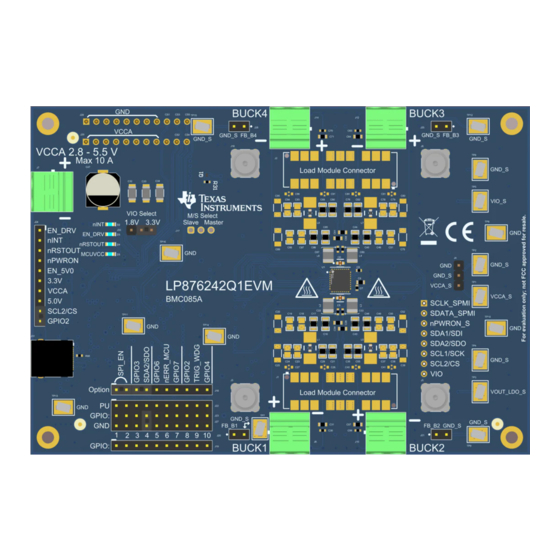
Figure 2-1. EVM Top View...........................................................................................................................................................
Figure 3-1. EVM Header J18.......................................................................................................................................................
Figure 3-2. EVM Bottom Side......................................................................................................................................................
Figure 5-1. Main Schematic Page.............................................................................................................................................
Figure 5-2. MCU Schematic Page.............................................................................................................................................
Figure 5-8. Layout Bottom, Layer 6...........................................................................................................................................
Blocks...........................................................................................................................................................4
Table 3-2. Test Point Descriptions...............................................................................................................................................
Table 3-3. Header J18 Description..............................................................................................................................................
Table 3-4. Header J33 VIO Voltage Select..................................................................................................................................
Table 3-6. DC Block.....................................................................................................................................................................
Switches...............................................................................................................................................................8
SLVUC20A - MARCH 2021 - REVISED AUGUST 2022
Submit Document Feedback
ABSTRACT
SLVUBT8
and the LP876242-Q1 Four 8.8-MHz Buck Converters for
Caution Caution Hot surface.
Contact may cause burns.
Do not touch!
Table of Contents
Interface.............................................................................................................................9
List of Figures
2
C Communication.................................................................................................................
1.................................................................................................................................................12
2...........................................................................................................................................13
3.............................................................................................................................................14
4.............................................................................................................................................15
5...........................................................................................................................................16
List of Tables
GPIO2/I2C/SPI.........................................................................................................................6
Copyright © 2022 Texas Instruments Incorporated
Table of Contents
LP876242-Q1 Evaluation Module
4
4
4
4
9
10
23
3
5
7
9
10
11
17
4
5
6
7
1
Advertisement
Table of Contents

Related Manuals for Texas Instruments LP876242-Q1


Summary of Contents for Texas Instruments LP876242-Q1
-
Page 1: Table Of Contents
User’s Guide LP876242-Q1 Evaluation Module ABSTRACT The LP876242-Q1 Evaluation Module (EVM) highlights the performance and flexibility of the LP876242-Q1 power management integrated circuit (PMIC) for xWR radar applications. Use this document in conjunction with the Scalable PMIC's GUI User's Guide SLVUBT8 and the LP876242-Q1 Four 8.8-MHz Buck Converters for... - Page 2 Table 3-8. EVM LED Indicators..............................8 Table 5-1. Bill of Materials................................18 Trademarks All trademarks are the property of their respective owners. LP876242-Q1 Evaluation Module SLVUC20A – MARCH 2021 – REVISED AUGUST 2022 Submit Document Feedback Copyright © 2022 Texas Instruments Incorporated...
-
Page 3: Introduction
(GUI) tool. 2 Getting Started Only a power supply and the EVM are required to evaluate and test the LP876242-Q1 default configuration under load conditions. To start evaluating the LP876242-Q1 follow the following steps. -
Page 4: The Gui Tool
Getting Started www.ti.com 2.1 The GUI Tool Texas Instruments provides a GUI tool to enable, configure, and evaluate the various features of the LP876242- Q1 with the EVM. Please refer to the GUI User's Guide SLVUBT8 for a more detailed description of this tool. -
Page 5: Figure 3-1. Evm Header J18
3.3 V. GPIO6 or GPIO7 supports the system error count nERR_MCU, GPIO7 Closed down from the MCU when the PMIC is in the Alternative function. SLVUC20A – MARCH 2021 – REVISED AUGUST 2022 LP876242-Q1 Evaluation Module Submit Document Feedback Copyright © 2022 Texas Instruments Incorporated... -
Page 6: Connectors
The corresponding DC capacitor footprints are marked on the bottom side of the PCB as shown in Figure 3-2 and summarized in Table 3-6 LP876242-Q1 Evaluation Module SLVUC20A – MARCH 2021 – REVISED AUGUST 2022 Submit Document Feedback Copyright © 2022 Texas Instruments Incorporated... -
Page 7: Dip Switches
GPIO signals if configured in high impedance state. See the Table 3-7 the descriptions of the switches. SLVUC20A – MARCH 2021 – REVISED AUGUST 2022 LP876242-Q1 Evaluation Module Submit Document Feedback Copyright © 2022 Texas Instruments Incorporated... -
Page 8: Evm Control And Gpio
LED is on when nINT is low. LED is on when EN_DRV is high. LED is on when nRSTOUT is low. EVM USB power indicator. LP876242-Q1 Evaluation Module SLVUC20A – MARCH 2021 – REVISED AUGUST 2022 Submit Document Feedback Copyright © 2022 Texas Instruments Incorporated... -
Page 9: Customization
PMIC receives and responds to commands on the SPI bus. Figure 4-1. Interface Settings for I C Communication SLVUC20A – MARCH 2021 – REVISED AUGUST 2022 LP876242-Q1 Evaluation Module Submit Document Feedback Copyright © 2022 Texas Instruments Incorporated... -
Page 10: Schematic, Layout, And Bill Of Materials
Schematic, Layout, and Bill of Materials www.ti.com 5 Schematic, Layout, and Bill of Materials Figure 5-1. Main Schematic Page LP876242-Q1 Evaluation Module SLVUC20A – MARCH 2021 – REVISED AUGUST 2022 Submit Document Feedback Copyright © 2022 Texas Instruments Incorporated... -
Page 11: Figure 5-2. Mcu Schematic Page
Schematic, Layout, and Bill of Materials Figure 5-2. MCU Schematic Page SLVUC20A – MARCH 2021 – REVISED AUGUST 2022 LP876242-Q1 Evaluation Module Submit Document Feedback Copyright © 2022 Texas Instruments Incorporated... -
Page 12: Figure 5-3. Layout Top, Layer 1
Schematic, Layout, and Bill of Materials www.ti.com Figure 5-3. Layout Top, Layer 1 LP876242-Q1 Evaluation Module SLVUC20A – MARCH 2021 – REVISED AUGUST 2022 Submit Document Feedback Copyright © 2022 Texas Instruments Incorporated... -
Page 13: Figure 5-4. Layout Ground, Layer 2
Schematic, Layout, and Bill of Materials Figure 5-4. Layout Ground, Layer 2 SLVUC20A – MARCH 2021 – REVISED AUGUST 2022 LP876242-Q1 Evaluation Module Submit Document Feedback Copyright © 2022 Texas Instruments Incorporated... -
Page 14: Figure 5-5. Layout Signal, Layer 3
Schematic, Layout, and Bill of Materials www.ti.com Figure 5-5. Layout Signal, Layer 3 LP876242-Q1 Evaluation Module SLVUC20A – MARCH 2021 – REVISED AUGUST 2022 Submit Document Feedback Copyright © 2022 Texas Instruments Incorporated... -
Page 15: Figure 5-6. Layout Signal, Layer 4
Schematic, Layout, and Bill of Materials Figure 5-6. Layout Signal, Layer 4 SLVUC20A – MARCH 2021 – REVISED AUGUST 2022 LP876242-Q1 Evaluation Module Submit Document Feedback Copyright © 2022 Texas Instruments Incorporated... -
Page 16: Figure 5-7. Layout Ground, Layer 5
Schematic, Layout, and Bill of Materials www.ti.com Figure 5-7. Layout Ground, Layer 5 LP876242-Q1 Evaluation Module SLVUC20A – MARCH 2021 – REVISED AUGUST 2022 Submit Document Feedback Copyright © 2022 Texas Instruments Incorporated... -
Page 17: Figure 5-8. Layout Bottom, Layer 6
Schematic, Layout, and Bill of Materials Figure 5-8. Layout Bottom, Layer 6 SLVUC20A – MARCH 2021 – REVISED AUGUST 2022 LP876242-Q1 Evaluation Module Submit Document Feedback Copyright © 2022 Texas Instruments Incorporated... - Page 18 10 V, +/- 10%, X7R, AEC-Q200 Grade 1, 1206 UUD1V151MNL1GS 150uF Nichicon CAP, AL, 150 uF, 35 8x10 V, +/- 20%, 0.17 ohm, LP876242-Q1 Evaluation Module SLVUC20A – MARCH 2021 – REVISED AUGUST 2022 Submit Document Feedback Copyright © 2022 Texas Instruments Incorporated...
- Page 19 USB TYPE C, R/A, USB TYPE C, R/A, FTSH-105-01-F-DV-K 1 Samtec Header (Shrouded), Header(Shrouded), 1.27mm, 5x2, Gold, 1.27mm, 5x2, SMT SLVUC20A – MARCH 2021 – REVISED AUGUST 2022 LP876242-Q1 Evaluation Module Submit Document Feedback Copyright © 2022 Texas Instruments Incorporated...
- Page 20 0.063 W, AEC-Q200 Grade 0, 0402 CRCW0402374KFKE 374k Vishay-Dale RES, 374 k, 1%, 0402 0.063 W, AEC-Q200 Grade 0, 0402 LP876242-Q1 Evaluation Module SLVUC20A – MARCH 2021 – REVISED AUGUST 2022 Submit Document Feedback Copyright © 2022 Texas Instruments Incorporated...
- Page 21 ESD Protection Array for High-Speed Data Interfaces, RSE0008A (UQFN-8) TPD4S012DRYR Texas Instruments 4-Channel USB ESD DRY0006A Solution with Power Clamp, DRY0006A (USON-6) SLVUC20A – MARCH 2021 – REVISED AUGUST 2022 LP876242-Q1 Evaluation Module Submit Document Feedback Copyright © 2022 Texas Instruments Incorporated...
- Page 22 DRV0006A (WSON-6) TLV73318PQDRVRQ Texas Instruments Capacitor-Free, DRV0006A 300-mA, Low- Dropout Regulator for Automotive, DRV0006A (WSON-6) NX3225SA-25.000M- CRYSTAL SMT_XTAL_3MM2_2 STD-CRS-2 25.0000MHZ 8PF LP876242-Q1 Evaluation Module SLVUC20A – MARCH 2021 – REVISED AUGUST 2022 Submit Document Feedback Copyright © 2022 Texas Instruments Incorporated...
-
Page 23: Additional Resources
Scalable PMIC's GUI User’s Guide • Texas Instruments, LP876242-Q1 Four 8.8-MHz Buck Converters for AWR and IWR MMICs data sheet 7 Revision History NOTE: Page numbers for previous revisions may differ from page numbers in the current version. Changes from Revision * (March 2021) to Revision A (August 2022) Page •... - Page 24 STANDARD TERMS FOR EVALUATION MODULES Delivery: TI delivers TI evaluation boards, kits, or modules, including any accompanying demonstration software, components, and/or documentation which may be provided together or separately (collectively, an “EVM” or “EVMs”) to the User (“User”) in accordance with the terms set forth herein.
- Page 25 www.ti.com Regulatory Notices: 3.1 United States 3.1.1 Notice applicable to EVMs not FCC-Approved: FCC NOTICE: This kit is designed to allow product developers to evaluate electronic components, circuitry, or software associated with the kit to determine whether to incorporate such items in a finished product and software developers to write software applications for use with the end product.
- Page 26 www.ti.com Concernant les EVMs avec antennes détachables Conformément à la réglementation d'Industrie Canada, le présent émetteur radio peut fonctionner avec une antenne d'un type et d'un gain maximal (ou inférieur) approuvé pour l'émetteur par Industrie Canada. Dans le but de réduire les risques de brouillage radioélectrique à...
- Page 27 www.ti.com EVM Use Restrictions and Warnings: 4.1 EVMS ARE NOT FOR USE IN FUNCTIONAL SAFETY AND/OR SAFETY CRITICAL EVALUATIONS, INCLUDING BUT NOT LIMITED TO EVALUATIONS OF LIFE SUPPORT APPLICATIONS. 4.2 User must read and apply the user guide and other available documentation provided by TI regarding the EVM prior to handling or using the EVM, including without limitation any warning or restriction notices.
- Page 28 Notwithstanding the foregoing, any judgment may be enforced in any United States or foreign court, and TI may seek injunctive relief in any United States or foreign court. Mailing Address: Texas Instruments, Post Office Box 655303, Dallas, Texas 75265 Copyright © 2019, Texas Instruments Incorporated...
- Page 29 TI products. TI’s provision of these resources does not expand or otherwise alter TI’s applicable warranties or warranty disclaimers for TI products. TI objects to and rejects any additional or different terms you may have proposed. IMPORTANT NOTICE Mailing Address: Texas Instruments, Post Office Box 655303, Dallas, Texas 75265 Copyright © 2022, Texas Instruments Incorporated...
Need help?
Do you have a question about the LP876242-Q1 and is the answer not in the manual?
Questions and answers