Table of Contents
Advertisement
Quick Links
www.ti.com
User's Guide
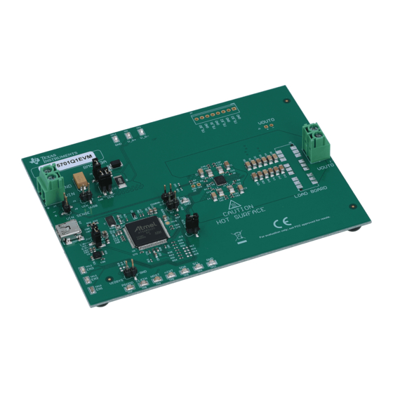
The LP875761Q1EVM Evaluation Module
This user's guide describes the operation of the BMC043 evaluation module for the LP875761-Q1 multi-phase 4-
core step-down converter from Texas Instruments (TI). The LP875761-Q1 is intended to be used in 4-phase
output configuration (see
and bill of materials (BOM).
1
Trademarks..............................................................................................................................................................................2
2
Overview..................................................................................................................................................................................3
Guide..................................................................................................................................................................3
3.1 Installing/Opening the Software.........................................................................................................................................
Setup...........................................................................................................................................................7
3.3 Notes on Efficiency Measurement Procedure..................................................................................................................
4 GUI Overview........................................................................................................................................................................
Tab...........................................................................................................................................................................10
4.2 Other Tabs and Menus.....................................................................................................................................................
4.3 Console............................................................................................................................................................................
5 Bill of Materials.....................................................................................................................................................................
Layout.........................................................................................................................................................................21
Schematics..............................................................................................................................................29
8 Revision History...................................................................................................................................................................
Figure 2-1. LP875761Q1EVM.....................................................................................................................................................
Figure 3-1. LP8757 Installer License Agreement........................................................................................................................
Figure 3-4. LP8757 Installation Complete...................................................................................................................................
Figure 3-5. Evaluation Software Graphical User Interface (GUI) When Board Connected.........................................................
Figure 3-6. Assert nRST..............................................................................................................................................................
Figure 3-7. Read Registers Buttons............................................................................................................................................
Figure 3-8. BUCK0 Enabled........................................................................................................................................................
Figure 3-9. Assert EN1................................................................................................................................................................
Figure 4-1. Accessing Direct Register Write..............................................................................................................................
Figure 4-2. Direct Register Access View...................................................................................................................................
Figure 4-4. Register Update Mode............................................................................................................................................
Figure 4-5. Config Tab of the LP8757 GUI................................................................................................................................
Console.....................................................................................................................................................17
Figure 4-8. Example of Command Use in Console...................................................................................................................
Figure 6-1. Board Stack-Up.......................................................................................................................................................
SNVU751 - OCTOBER 2020
Submit Document Feedback
Table
2-1). The user's guide also provides design information including the schematic
Warning Warning Hot surface.
Contact may cause burns.
Do not touch!
Table of Contents
List of Figures
Installation.................................................................................................................................5
Folder........................................................................................................................................5
Values........................................................................................................................................14
GUI.................................................................................................................................16
LP875761-Q1EVM.........................................................................................................................22
Copyright © 2020 Texas Instruments Incorporated
ABSTRACT
Table of Contents
The LP875761Q1EVM Evaluation Module
4
10
10
11
17
19
30
3
4
6
6
7
8
8
9
12
13
15
16
18
21
1
Advertisement
Table of Contents

Related Manuals for Texas Instruments LP875761Q1EVM


Summary of Contents for Texas Instruments LP875761Q1EVM
-
Page 1: Table Of Contents
The LP875761Q1EVM Evaluation Module ABSTRACT This user’s guide describes the operation of the BMC043 evaluation module for the LP875761-Q1 multi-phase 4- core step-down converter from Texas Instruments (TI). The LP875761-Q1 is intended to be used in 4-phase output configuration (see Table 2-1). -
Page 2: Trademarks
Configurations............................3 Table 4-1. Mode Information..............................Table 4-2. I2C-Compatible Bus Support.............................11 Table 4-3. Console Macros................................ Table 5-1. Bill of Materials for LP875761Q1EVM........................1 Trademarks Microsoft Windows XP ® is a registered trademark of Microsoft Corporation. All other trademarks are the property of their respective owners. -
Page 3: Overview
Upon opening the LP875761Q1EVM package, ensure that the following items are included: • LP875761Q1EVM Evaluation Board • USB Cable If any of the items are missing, contact the closest Texas Instruments Product Information Center to inquire about a replacement. SNVU751 – OCTOBER 2020 The LP875761Q1EVM Evaluation Module Submit Document Feedback... -
Page 4: Installing/Opening The Software
2. On the Evaluation SW window bottom right corner you should see text Hardware connected. Refer to Figure 3-5. Figure 3-1. LP8757 Installer License Agreement The LP875761Q1EVM Evaluation Module SNVU751 – OCTOBER 2020 Submit Document Feedback Copyright © 2020 Texas Instruments Incorporated... -
Page 5: Figure 3-2. Features Of Lp8757 Installation
Quick Setup Guide Figure 3-2. Features of LP8757 Installation Figure 3-3. LP8757 Destination Folder SNVU751 – OCTOBER 2020 The LP875761Q1EVM Evaluation Module Submit Document Feedback Copyright © 2020 Texas Instruments Incorporated... -
Page 6: Figure 3-4. Lp8757 Installation Complete
Quick Setup Guide www.ti.com Figure 3-4. LP8757 Installation Complete Figure 3-5. Evaluation Software Graphical User Interface (GUI) When Board Connected The LP875761Q1EVM Evaluation Module SNVU751 – OCTOBER 2020 Submit Document Feedback Copyright © 2020 Texas Instruments Incorporated... -
Page 7: Power Supply Setup
3.2 Power Supply Setup To power up the EVM, one power supply is needed. For full-load testing of the LP875761Q1EVM, a DC-power supply capable of at least 10 A and 5 V is required. 5 A is suggested as a practical minimum for partial load. The power supply is connected to the EVM using connector J4. -
Page 8: Figure 3-7. Read Registers Buttons
Quick Setup Guide www.ti.com Figure 3-7. Read Registers Buttons Figure 3-8. BUCK0 Enabled The LP875761Q1EVM Evaluation Module SNVU751 – OCTOBER 2020 Submit Document Feedback Copyright © 2020 Texas Instruments Incorporated... -
Page 9: Figure 3-9. Assert En1
Quick Setup Guide Figure 3-9. Assert EN1 SNVU751 – OCTOBER 2020 The LP875761Q1EVM Evaluation Module Submit Document Feedback Copyright © 2020 Texas Instruments Incorporated... -
Page 10: Notes On Efficiency Measurement Procedure
The recommended start-up sequence for LP875761Q1 is to first assert NRST, then write all needed configuration bits by using the GUI, and then enable one or more of th buck regulators by ENx pin or EN_BUCKx bit. The LP875761Q1EVM Evaluation Module SNVU751 – OCTOBER 2020 Submit Document Feedback Copyright © 2020 Texas Instruments Incorporated... -
Page 11: Other Tabs And Menus
When using direct register access, TI recommends un-checking the poll status check-box. This way the GUI will only do the reads and writes commanded from the direct access dialog. SNVU751 – OCTOBER 2020 The LP875761Q1EVM Evaluation Module Submit Document Feedback Copyright © 2020 Texas Instruments Incorporated... -
Page 12: Figure 4-1. Accessing Direct Register Write
GUI Overview www.ti.com Figure 4-1. Accessing Direct Register Write The LP875761Q1EVM Evaluation Module SNVU751 – OCTOBER 2020 Submit Document Feedback Copyright © 2020 Texas Instruments Incorporated... -
Page 13: Figure 4-2. Direct Register Access View
GUI Overview Figure 4-2. Direct Register Access View SNVU751 – OCTOBER 2020 The LP875761Q1EVM Evaluation Module Submit Document Feedback Copyright © 2020 Texas Instruments Incorporated... -
Page 14: Figure 4-3. Selecting Register Values
GUI Overview www.ti.com Figure 4-3. Selecting Register Values The LP875761Q1EVM Evaluation Module SNVU751 – OCTOBER 2020 Submit Document Feedback Copyright © 2020 Texas Instruments Incorporated... -
Page 15: Figure 4-4. Register Update Mode
Refer to the LP875761-Q1 data sheet for explanation of the functions. See following images for reference of the Config and Advanced tabs. SNVU751 – OCTOBER 2020 The LP875761Q1EVM Evaluation Module Submit Document Feedback Copyright © 2020 Texas Instruments Incorporated... -
Page 16: Figure 4-5. Config Tab Of The Lp8757 Gui
GUI Overview www.ti.com Figure 4-5. Config Tab of the LP8757 GUI Figure 4-6. Advanced Tab of LP8757 GUI The LP875761Q1EVM Evaluation Module SNVU751 – OCTOBER 2020 Submit Document Feedback Copyright © 2020 Texas Instruments Incorporated... -
Page 17: Console
See an example Figure 4-8. The console has a number of integrated macros that are listed in Table 4-3. Figure 4-7. Opening Console SNVU751 – OCTOBER 2020 The LP875761Q1EVM Evaluation Module Submit Document Feedback Copyright © 2020 Texas Instruments Incorporated... -
Page 18: Figure 4-8. Example Of Command Use In Console
The LP875761Q1EVM Evaluation Module SNVU751 – OCTOBER 2020 Submit Document Feedback Copyright © 2020 Texas Instruments Incorporated... -
Page 19: Bill Of Materials
R27, R28, R29) must be removed to prevent possible damage to the microcontroller I/O pins. In open- drain configuration the microcontroller internal pullups are enabled by the GUI and pullup resistors R14 to R20 are not needed. Table 5-1. Bill of Materials for LP875761Q1EVM Designator Description... - Page 20 Bill of Materials www.ti.com Table 5-1. Bill of Materials for LP875761Q1EVM (continued) Designator Description Manufacturer Part Number Qty. Inductor, Wirewound, Ferrite, 10 µH, 0.12 Taiyo Yuden LB2012T100KR A, 0.5 Ω, SMD LBL1 Thermal Transfer Printable Labels, Brady THT-13-457-10 1.250" W x 0.250" H - 10,000 per roll R1, R2, R3, R4 RES, 3.9, 5%, 0.063 W, AEC-Q200...
-
Page 21: Board Layout
Board Layout 6 Board Layout This section describes the board layout of the LP875761Q1EVM. See the LP875761-Q1 data sheet for specific PCB layout recommendations. The board is constructed on a 4-layer PCB. using 55-µm copper on top and bottom layers to reduce resistance and improve heat transfer. -
Page 22: Figure 6-2. Top View Of The Lp875761-Q1Evm
Board Layout www.ti.com Figure 6-2. Top View of the LP875761-Q1EVM The LP875761Q1EVM Evaluation Module SNVU751 – OCTOBER 2020 Submit Document Feedback Copyright © 2020 Texas Instruments Incorporated... -
Page 23: Figure 6-3. Component Placement Top Layer
Board Layout Figure 6-3. Component Placement Top Layer SNVU751 – OCTOBER 2020 The LP875761Q1EVM Evaluation Module Submit Document Feedback Copyright © 2020 Texas Instruments Incorporated... -
Page 24: Figure 6-4. Component Placement Bottom Layer
Board Layout www.ti.com Figure 6-4. Component Placement Bottom Layer The LP875761Q1EVM Evaluation Module SNVU751 – OCTOBER 2020 Submit Document Feedback Copyright © 2020 Texas Instruments Incorporated... - Page 25 EMI. Also snubber circuits are placed next to SW nets for EMI reduction. Multiple GND vias are used to provide solid ground around the LP875761-Q1 device. Figure 6-5. Top Layer SNVU751 – OCTOBER 2020 The LP875761Q1EVM Evaluation Module Submit Document Feedback Copyright © 2020 Texas Instruments Incorporated...
- Page 26 GND plane close to top layer (0.143 mm) helps to reduce parasitic inductance. Holes in the plane are under inductor footprint (SW node) to reduce parasitic capacitance of the SW node, thus reducing noise coupling and improving efficiency. Figure 6-6. Mid-Layer1 The LP875761Q1EVM Evaluation Module SNVU751 – OCTOBER 2020 Submit Document Feedback Copyright © 2020 Texas Instruments Incorporated...
- Page 27 VIN supply is routed in this layer between the ground planes to reduce radiated emissions. VIN and GND vias are placed in hatched pattern to avoid large gaps in these planes. Figure 6-7. Mid-Layer2 SNVU751 – OCTOBER 2020 The LP875761Q1EVM Evaluation Module Submit Document Feedback Copyright © 2020 Texas Instruments Incorporated...
- Page 28 Input capacitors and filters are placed under the LP875761-Q1 into bottom layer. This allows closer placement of the inductors and input components reducing SW and VIN net areas and improving EMI. Figure 6-8. Bottom Layer (note mirror view) The LP875761Q1EVM Evaluation Module SNVU751 – OCTOBER 2020 Submit Document Feedback Copyright © 2020 Texas Instruments Incorporated...
-
Page 29: Lp875761Q1Evm Schematics
LP875761Q1EVM Schematics 7 LP875761Q1EVM Schematics Figure 7-1. LP875761Q1EVM Schematic SNVU751 – OCTOBER 2020 The LP875761Q1EVM Evaluation Module Submit Document Feedback Copyright © 2020 Texas Instruments Incorporated... -
Page 30: Revision History
Revision History www.ti.com 8 Revision History NOTE: Page numbers for previous revisions may differ from page numbers in the current version. The LP875761Q1EVM Evaluation Module SNVU751 – OCTOBER 2020 Submit Document Feedback Copyright © 2020 Texas Instruments Incorporated... - Page 31 STANDARD TERMS FOR EVALUATION MODULES Delivery: TI delivers TI evaluation boards, kits, or modules, including any accompanying demonstration software, components, and/or documentation which may be provided together or separately (collectively, an “EVM” or “EVMs”) to the User (“User”) in accordance with the terms set forth herein.
- Page 32 www.ti.com Regulatory Notices: 3.1 United States 3.1.1 Notice applicable to EVMs not FCC-Approved: FCC NOTICE: This kit is designed to allow product developers to evaluate electronic components, circuitry, or software associated with the kit to determine whether to incorporate such items in a finished product and software developers to write software applications for use with the end product.
- Page 33 www.ti.com Concernant les EVMs avec antennes détachables Conformément à la réglementation d'Industrie Canada, le présent émetteur radio peut fonctionner avec une antenne d'un type et d'un gain maximal (ou inférieur) approuvé pour l'émetteur par Industrie Canada. Dans le but de réduire les risques de brouillage radioélectrique à...
- Page 34 www.ti.com EVM Use Restrictions and Warnings: 4.1 EVMS ARE NOT FOR USE IN FUNCTIONAL SAFETY AND/OR SAFETY CRITICAL EVALUATIONS, INCLUDING BUT NOT LIMITED TO EVALUATIONS OF LIFE SUPPORT APPLICATIONS. 4.2 User must read and apply the user guide and other available documentation provided by TI regarding the EVM prior to handling or using the EVM, including without limitation any warning or restriction notices.
- Page 35 Notwithstanding the foregoing, any judgment may be enforced in any United States or foreign court, and TI may seek injunctive relief in any United States or foreign court. Mailing Address: Texas Instruments, Post Office Box 655303, Dallas, Texas 75265 Copyright © 2019, Texas Instruments Incorporated...
- Page 36 TI products. TI’s provision of these resources does not expand or otherwise alter TI’s applicable warranties or warranty disclaimers for TI products.IMPORTANT NOTICE Mailing Address: Texas Instruments, Post Office Box 655303, Dallas, Texas 75265 Copyright © 2021, Texas Instruments Incorporated...
Need help?
Do you have a question about the LP875761Q1EVM and is the answer not in the manual?
Questions and answers