
Subscribe to Our Youtube Channel
Related Manuals for Texas Instruments LP8861-Q1


Summary of Contents for Texas Instruments LP8861-Q1
- Page 1 Using the LP8861-Q1EVM Evaluation Module User's Guide Literature Number: SNVU456 July 2015...
-
Page 2: Table Of Contents
About this Manual ..............Related Documentation from Texas Instruments ......................FCC Warning ....................If You Need Assistance ......................... Introduction ..................Description of the LP8861-Q1 Device ........................Features ....................... Applications ........................Hardware Setup ........................Board Layout ................Start-Up of the EVM and Power Sequences ................ - Page 3 Forward Voltage for Cree Xlamp ML-B LEDs Excel is a registered trademark of Microsoft Corporation. All other trademarks are the property of their respective owners. SNVU456 – July 2015 List of Figures Submit Documentation Feedback Copyright © 2015, Texas Instruments Incorporated...
-
Page 4: Preface
For evaluation purposes, the EVM has been tested over a 4.5-V to 40-V input range. This voltage range is within the recommended operating range for input voltage of the LP8861-Q1. Users are cautioned to evaluate their specific operating conditions and choose components with the appropriate voltage ratings before designing this circuitry into a final product. -
Page 5: Description Of The Lp8861-Q1 Device
LED life time. The input voltage range for LP8861-Q1 is from 4.5 V to 40 V to support car stop/start and load dump condition. The LP8861-Q1 device supports PWM brightness dimming ratio up to 10 000:1 for input PWM frequency of 200 Hz. -
Page 6: Hardware Setup
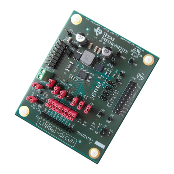
Hardware Setup www.ti.com Hardware Setup Figure 1 shows connectors and main components on the LP8861-Q1 board. CONTROL POINTS CONTROL POINTS CONNECTOR INPUT VOLTAGE OUTPUT CONFIGURATION CONTROL POINTS SHUNTS FAULT CONTROL POINTS Figure 1. Evaluation Board Connectors and Setup LP8861-Q1EVM Evaluation Module SNVU456 –... -
Page 7: Board Layout
Board Layout www.ti.com Board Layout Figure 2. Top Layer Figure 3. Bottom Layer (GND) See the LP8861-Q1 datasheet (SNVSA50) for PCB layout guidelines. SNVU456 – July 2015 LP8861-Q1EVM Evaluation Module Submit Documentation Feedback Copyright © 2015, Texas Instruments Incorporated... -
Page 8: Start-Up Of The Evm And Power Sequences
Input (BATTERY) voltage range is 4.5 V to 40 V. The LP8861-Q1 has a dual function VDDIO/EN pin. By default, VDDIO/EN = 3.3 V is generated automatically on the EVM from battery input voltage via jumpers J1 and J26. VDDIO/EN acts as enable for the device as well as supply/reference voltage for IO logic. -
Page 9: Shutdown Sequence
Shutdown Sequence The backlight is shut down (LEDs turned off) by setting PWM input low or when VDDIO/EN = 0. If VDDIO/EN is set low, the LP8861-Q1 will enter low power mode with internal LDO disabled. SNVU456 – July 2015... -
Page 10: Boost Converter
J3. When spread spectrum is enabled, boost switching frequency is modulated ±3% from set frequency with 1.875 kHz modulation frequency. If an external frequency is detected at SYNC pin, the LP8861-Q1 starts to synchronize boost with this frequency. Frequency should be higher than the switching frequency set by R... -
Page 11: Voltage Control
88% of maximum voltage. Boost output voltage is adjusted automatically based on LED current sink headroom voltage. Default setting for boost maximum voltage is 37 V (R12 is 750 kΩ). SNVU456 – July 2015 LP8861-Q1EVM Evaluation Module Submit Documentation Feedback Copyright © 2015, Texas Instruments Incorporated... -
Page 12: Led Current Sinks
An external digital PWM signal can be connected to connector J18. For test purposes the PWM input of the LP8861-Q1 can be connected to ground to turn off LEDs or connected to VDDIO/EN to set up 100% brightness using jumper J2. -
Page 13: External Temperature Sensor Functionality
External Temperature Sensor Functionality www.ti.com External Temperature Sensor Functionality Overview The LP8861-Q1 has an optional feature to decrease automatically LED current when LED overheating is detected with an external NTC sensor. See the LP8861-Q1 data sheet (SNVSA50) for details. Calculator An Excel calculator is available to choose components for the temperature compensation with an ®... -
Page 14: Evaluation Board Schematic
Evaluation Board Schematic www.ti.com Evaluation Board Schematic Figure 10. Evaluation Board Schematic LP8861-Q1EVM Evaluation Module SNVU456 – July 2015 Submit Documentation Feedback Copyright © 2015, Texas Instruments Incorporated... -
Page 15: Bill Of Materials
RES, 160 k, 1%, 0.1 W, 0603 Vishay-Dale CRCW0603160KFKEA RES, 24.0k ohm, 1%, 0.1W, 0603 Yageo America RC0603FR-0724KL RES, 1.80 k, 1%, 0.1 W, 0603 Yageo America RC0603FR-071K8L SNVU456 – July 2015 LP8861-Q1EVM Evaluation Module Submit Documentation Feedback Copyright © 2015, Texas Instruments Incorporated... - Page 16 Texas Instruments TLVH431AQDBVRQ1 PRECISION SHUNT REGULATOR, DBV0005A Some boards shipped with pre-production silicon marked as P8861Q1 53TG4 ES11 with adaptive SW pin current limit disabled. LP8861-Q1EVM Evaluation Module SNVU456 – July 2015 Submit Documentation Feedback Copyright © 2015, Texas Instruments Incorporated...
-
Page 17: Appendix A: Led Load Board
NOTE: The LED board is not included with the EVM -- contact your local TI sales representative if board is needed. Figure 11. LED Load Board - Top Side Figure 12. LED Load Board - Bottom View SNVU456 – July 2015 LP8861-Q1EVM Evaluation Module Submit Documentation Feedback Copyright © 2015, Texas Instruments Incorporated... - Page 18 J124 D119 J104 J125 D100 D120 J105 J126 J106 J127 10.0 10.0 10.0 10.0 10.0 10.0 Figure 13. LED Load Board - Schematic Diagram LP8861-Q1EVM Evaluation Module SNVU456 – July 2015 Submit Documentation Feedback Copyright © 2015, Texas Instruments Incorporated...
- Page 19 J130 Header, 100mi, 7x1 Samtec TSW-107-07-G-S D1...D120 Cool White SMD LED XLamp mL-B Cree MLBAWT-A1-0000-000W51 Figure 14. Forward Voltage for Cree Xlamp ML-B LEDs SNVU456 – July 2015 LP8861-Q1EVM Evaluation Module Submit Documentation Feedback Copyright © 2015, Texas Instruments Incorporated...
- Page 20 STANDARD TERMS AND CONDITIONS FOR EVALUATION MODULES Delivery: TI delivers TI evaluation boards, kits, or modules, including any accompanying demonstration software, components, or documentation (collectively, an “EVM” or “EVMs”) to the User (“User”) in accordance with the terms and conditions set forth herein. Acceptance of the EVM is expressly subject to the following terms and conditions.
- Page 21 FCC Interference Statement for Class B EVM devices NOTE: This equipment has been tested and found to comply with the limits for a Class B digital device, pursuant to part 15 of the FCC Rules. These limits are designed to provide reasonable protection against harmful interference in a residential installation.
- Page 22 【無線電波を送信する製品の開発キットをお使いになる際の注意事項】 開発キットの中には技術基準適合証明を受けて いないものがあります。 技術適合証明を受けていないもののご使用に際しては、電波法遵守のため、以下のいずれかの 措置を取っていただく必要がありますのでご注意ください。 1. 電波法施行規則第6条第1項第1号に基づく平成18年3月28日総務省告示第173号で定められた電波暗室等の試験設備でご使用 いただく。 2. 実験局の免許を取得後ご使用いただく。 3. 技術基準適合証明を取得後ご使用いただく。 なお、本製品は、上記の「ご使用にあたっての注意」を譲渡先、移転先に通知しない限り、譲渡、移転できないものとします。 上記を遵守頂けない場合は、電波法の罰則が適用される可能性があることをご留意ください。 日本テキサス・イ ンスツルメンツ株式会社 東京都新宿区西新宿6丁目24番1号 西新宿三井ビル 3.3.3 Notice for EVMs for Power Line Communication: Please see http://www.tij.co.jp/lsds/ti_ja/general/eStore/notice_02.page 電力線搬送波通信についての開発キットをお使いになる際の注意事項については、次のところをご覧くださ い。http://www.tij.co.jp/lsds/ti_ja/general/eStore/notice_02.page SPACER EVM Use Restrictions and Warnings: 4.1 EVMS ARE NOT FOR USE IN FUNCTIONAL SAFETY AND/OR SAFETY CRITICAL EVALUATIONS, INCLUDING BUT NOT LIMITED TO EVALUATIONS OF LIFE SUPPORT APPLICATIONS.
- Page 23 Notwithstanding the foregoing, any judgment may be enforced in any United States or foreign court, and TI may seek injunctive relief in any United States or foreign court. Mailing Address: Texas Instruments, Post Office Box 655303, Dallas, Texas 75265 Copyright © 2015, Texas Instruments Incorporated...
- Page 24 IMPORTANT NOTICE Texas Instruments Incorporated and its subsidiaries (TI) reserve the right to make corrections, enhancements, improvements and other changes to its semiconductor products and services per JESD46, latest issue, and to discontinue any product or service per JESD48, latest issue.
- Page 25 Mouser Electronics Authorized Distributor Click to View Pricing, Inventory, Delivery & Lifecycle Information: Texas Instruments LP8861Q1EVM...
Need help?
Do you have a question about the LP8861-Q1 and is the answer not in the manual?
Questions and answers