Table of Contents
Advertisement
Quick Links
www.ti.com
User's Guide
LP877451Q1EVM Evaluation Module
The LP87745-Q1 device is designed to meet the power management requirements of the AWR and IWR MMICs
in various automotive and industrial radar applications. The device has three step-down DC/DC converters,
a 5 V boost converter and a 1.8 V/3.3 V LDO. The LDO is powered from the boost and intended for xWR
and peripheral devices IO supply. The device is controlled by an SPI serial interface and by enable signal.
The step-down DC/DC converters support programmable switching frequency of 17.6 MHz, 8.8 MHz or 4.4
MHz and have low noise across wide frequency range which enables LDO-free power solution with minimal
or no additional passive filtering. LP87745-Q1 device offers flexible external component selection to optimize
the solution in terms of performance or cost. The features of the device target safety-relevant applications with
system-safety requirements up to ASIL-C level.
This user's guide provides instructions to power up and evaluate LP87745-Q1 device using the
LP877451Q1EVM evaluation module (EVM) and software user interface (LP87745-Q1 GUI). By default
LP877451Q1EVM has LP877451A1RXVRQ1 device OTP version (17.6 MHz, Low noise use case BOM), but
this EVM can also be used to evaluate another OTP device from LP8774x-Q1 product family.
3 Jumpers and connectors.......................................................................................................................................................
Points..........................................................................................................................................................................6
Started........................................................................................................................................................................8
4.1
GUI.....................................................................................................................................................................................8
4.2 GUI Installation and working with GUI...............................................................................................................................
5
Watchdog...............................................................................................................................................................................12
6 Schematics, Layout and BOM.............................................................................................................................................
Diagram..........................................................................................................................................................15
6.2 PCB Layer Diagram.........................................................................................................................................................
6.3 Components List..............................................................................................................................................................
7 Revision History...................................................................................................................................................................
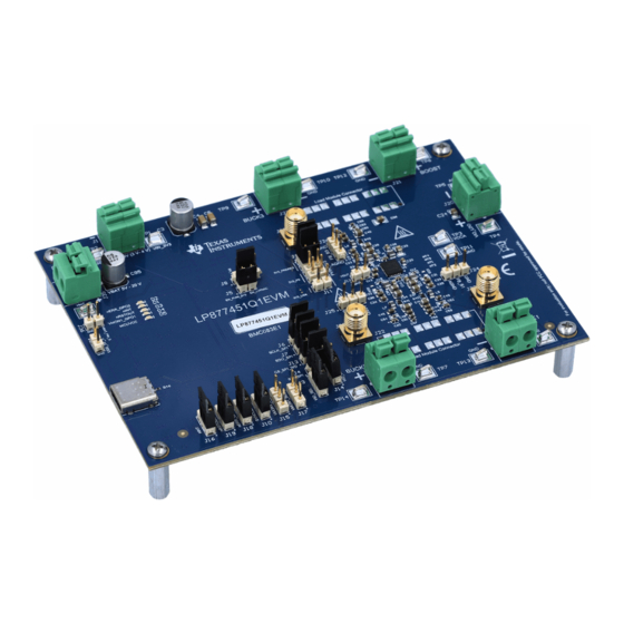
Figure 1-1. EVM Top-View Diagram With Basic Connections and Default Jumpers...................................................................
Figure 4-1. GUI Front Page.........................................................................................................................................................
Figure 4-2. GUI Configuration Page..........................................................................................................................................
Figure 5-2. GUI Watchdog Validation Configuration .................................................................................................................
Schematic......................................................................................................................................................15
Schematic...........................................................................................................................................16
Figure 6-3. MCU Schematic......................................................................................................................................................
SNVU769A - SEPTEMBER 2021 - REVISED OCTOBER 2022
ABSTRACT
Contact may cause burns.
Table of Contents
Connections..........................................................................................................................2
Requirements...................................................................................................3
List of Figures
Page...........................................................................................................................................11
Mode.........................................................................................................................12
..................................................................................................................................13
Copyright © 2022 Texas Instruments Incorporated
CAUTION
Hot surface.
Do not touch!
Table of Contents
4
8
14
18
18
22
2
9
10
13
17
1
Advertisement
Table of Contents

Subscribe to Our Youtube Channel
Related Manuals for Texas Instruments LP877451Q1EVM


Summary of Contents for Texas Instruments LP877451Q1EVM
-
Page 1: Table Of Contents
LP877451Q1EVM evaluation module (EVM) and software user interface (LP87745-Q1 GUI). By default LP877451Q1EVM has LP877451A1RXVRQ1 device OTP version (17.6 MHz, Low noise use case BOM), but this EVM can also be used to evaluate another OTP device from LP8774x-Q1 product family. -
Page 2: Top View With Basic External Connections
(5V-20V) VIO_LDO LP877451Q1EVM Default Jumpers BUCK2 VOUT BUCK1 VOUT Figure 1-1. EVM Top-View Diagram With Basic Connections and Default Jumpers LP877451Q1EVM Evaluation Module SNVU769A – SEPTEMBER 2021 – REVISED OCTOBER 2022 Submit Document Feedback Copyright © 2022 Texas Instruments Incorporated... -
Page 3: Input, Output Voltages, And Load Current Requirements
If all the regulators are loaded with maximum load current simultaneously, PMIC and PCB can become hot. Make sure that PMIC junction temperature does not exceed 150 °C. SNVU769A – SEPTEMBER 2021 – REVISED OCTOBER 2022 LP877451Q1EVM Evaluation Module Submit Document Feedback Copyright © 2022 Texas Instruments Incorporated... -
Page 4: Jumpers And Connectors
3 Jumpers and connectors LP877451Q1EVM has many terminal blocks, jumpers and test points to offer certain flexibility to help users to verify the EVM according to their application conditions. However, the EVM is pre-configured with default jumper settings and users can power up the regulators without the need of jumper modifications. Setting these jumpers correctly for the correct function of the EVM is important. - Page 5 MCU port through level shifter Pins 2 and 3 (series resistors must be mounted if this option is used) SNVU769A – SEPTEMBER 2021 – REVISED OCTOBER 2022 LP877451Q1EVM Evaluation Module Submit Document Feedback Copyright © 2022 Texas Instruments Incorporated...
-
Page 6: Test Points
Test point to measure the BUCK3 feedback FB_B3 signal SMA connector for BUCK3 noise measurement SMA connector for BUCK2 noise measurement LP877451Q1EVM Evaluation Module SNVU769A – SEPTEMBER 2021 – REVISED OCTOBER 2022 Submit Document Feedback Copyright © 2022 Texas Instruments Incorporated... - Page 7 Connector Name Description SMA connector for BUCK1 noise measurement Test point to measure 5 V supply from USB USB_5V_S cable SNVU769A – SEPTEMBER 2021 – REVISED OCTOBER 2022 LP877451Q1EVM Evaluation Module Submit Document Feedback Copyright © 2022 Texas Instruments Incorporated...
-
Page 8: Getting Started
GUI. 4.1 GUI Texas Instruments provides a simple to use LP87745-Q1 GUI tool to enable, configure, and evaluate the various features of the LP87745-Q1 device on the EVM. Please refer to the GUI README.md file in the GUI tool's Help->View README.md tab for a more detailed description of this tool. -
Page 9: Figure 4-1. Gui Front Page
GUI Register Map Page. For example, output voltages, startup and shutdown delays and peak current limits can be changed for each buck converter. SNVU769A – SEPTEMBER 2021 – REVISED OCTOBER 2022 LP877451Q1EVM Evaluation Module Submit Document Feedback Copyright © 2022 Texas Instruments Incorporated... -
Page 10: Figure 4-2. Gui Configuration Page
Figure 4-2. GUI Configuration Page In the register map page shown in Figure 4-3, registers can be read or written to. LP877451Q1EVM Evaluation Module SNVU769A – SEPTEMBER 2021 – REVISED OCTOBER 2022 Submit Document Feedback Copyright © 2022 Texas Instruments Incorporated... -
Page 11: Figure 4-3. Gui Register Map Page
Getting Started Figure 4-3. GUI Register Map Page SNVU769A – SEPTEMBER 2021 – REVISED OCTOBER 2022 LP877451Q1EVM Evaluation Module Submit Document Feedback Copyright © 2022 Texas Instruments Incorporated... -
Page 12: Watchdog
Figure 5-3. For further information on watchdog configuration, refer to the data sheet of LP8774x-Q1 SNVSBE7 for watchdog section. LP877451Q1EVM Evaluation Module SNVU769A – SEPTEMBER 2021 – REVISED OCTOBER 2022 Submit Document Feedback Copyright © 2022 Texas Instruments Incorporated... -
Page 13: Figure 5-2. Gui Watchdog Validation Configuration
Watchdog Figure 5-2. GUI Watchdog Validation Configuration Figure 5-3. GUI Watchdog Configuration SNVU769A – SEPTEMBER 2021 – REVISED OCTOBER 2022 LP877451Q1EVM Evaluation Module Submit Document Feedback Copyright © 2022 Texas Instruments Incorporated... -
Page 14: Schematics, Layout And Bom
6 Schematics, Layout and BOM This section contains the schematics, layout and the bill of materials for the LP87745Q1EVM. LP877451Q1EVM Evaluation Module SNVU769A – SEPTEMBER 2021 – REVISED OCTOBER 2022 Submit Document Feedback Copyright © 2022 Texas Instruments Incorporated... -
Page 15: Schematic Diagram
6.1 Schematic Diagram This section includes images of the EVM schematics and different layers of the layout. Figure 6-1. PMIC Schematic SNVU769A – SEPTEMBER 2021 – REVISED OCTOBER 2022 LP877451Q1EVM Evaluation Module Submit Document Feedback Copyright © 2022 Texas Instruments Incorporated... -
Page 16: Figure 6-2. Preregulator Schematic
Schematics, Layout and BOM www.ti.com Figure 6-2. Preregulator Schematic LP877451Q1EVM Evaluation Module SNVU769A – SEPTEMBER 2021 – REVISED OCTOBER 2022 Submit Document Feedback Copyright © 2022 Texas Instruments Incorporated... -
Page 17: Figure 6-3. Mcu Schematic
Schematics, Layout and BOM Figure 6-3. MCU Schematic SNVU769A – SEPTEMBER 2021 – REVISED OCTOBER 2022 LP877451Q1EVM Evaluation Module Submit Document Feedback Copyright © 2022 Texas Instruments Incorporated... -
Page 18: Pcb Layer Diagram
CAP, CERM, 0.1 uF, 16 V, +/- 10%, GCM155R71C104KA55D MuRata C57, C58, C76, X7R, 0402 C81, C83, C84, C86, C93, C94 LP877451Q1EVM Evaluation Module SNVU769A – SEPTEMBER 2021 – REVISED OCTOBER 2022 Submit Document Feedback Copyright © 2022 Texas Instruments Incorporated... - Page 19 C0603 22 pF X7R 30ppm/°C 10.00% C0603C220K5RACAUTO KEMET 50 V C113 CAP, CERM, 1 uF, 25 V, +/- 10%, C0805C105K3RACTU Kemet X7R, 0805 SNVU769A – SEPTEMBER 2021 – REVISED OCTOBER 2022 LP877451Q1EVM Evaluation Module Submit Document Feedback Copyright © 2022 Texas Instruments Incorporated...
- Page 20 RES 0 OHM JUMPER 1/4W 0603 HCJ0603ZT0R00 Stackpole Electronics RES, 8.25 k, 1%, 0.1 W, AEC-Q200 CRCW06038K25FKEA Vishay-Dale Grade 0, 0603 LP877451Q1EVM Evaluation Module SNVU769A – SEPTEMBER 2021 – REVISED OCTOBER 2022 Submit Document Feedback Copyright © 2022 Texas Instruments Incorporated...
- Page 21 Boost for AWR and IWR Radar Sensors Automotive Catalog, Dual, 200mA, TLV7103318QDSERQ1 Texas Instruments Low-IQ Low-Dropout Regulator for Portable Devices, DSE0006A (WSON-6) SNVU769A – SEPTEMBER 2021 – REVISED OCTOBER 2022 LP877451Q1EVM Evaluation Module Submit Document Feedback Copyright © 2022 Texas Instruments Incorporated...
-
Page 22: Revision History
Updated the Figure 4-1 ............................8 • Updated the watchdog section......................... • Updated the schematic diagrams........................• Updated the bill of materials..........................LP877451Q1EVM Evaluation Module SNVU769A – SEPTEMBER 2021 – REVISED OCTOBER 2022 Submit Document Feedback Copyright © 2022 Texas Instruments Incorporated... - Page 23 TI products. TI’s provision of these resources does not expand or otherwise alter TI’s applicable warranties or warranty disclaimers for TI products. TI objects to and rejects any additional or different terms you may have proposed. IMPORTANT NOTICE Mailing Address: Texas Instruments, Post Office Box 655303, Dallas, Texas 75265 Copyright © 2022, Texas Instruments Incorporated...
Need help?
Do you have a question about the LP877451Q1EVM and is the answer not in the manual?
Questions and answers