Table of Contents
Advertisement
Quick Links
1
Introduction
The LP8557IEVM evaluation kit requires external power and is controlled via I2C. It includes a USB2ANY
adapter board and instructions on downloading and installing the user software.
2
LP8557IEVM Instructions
External power must be provided to the part. A standard USB to mini cable must be connected to the
USB2ANY from a PC. The I
part requires. For proper operation, first power the evaluation board; the USB2ANY should then be
plugged into the PC before the interface program is opened. Once the program is executed, a basic
interface window will open.
SNVU371 – December 2013
Submit Documentation Feedback
2
C-compatible interface program provides all of the control that the LP8557
Figure 1. User Interface
Copyright © 2013, Texas Instruments Incorporated
SNVU371 – December 2013
LP8557IEVM User Guide
LP8557IEVM User Guide
User's Guide
1
Advertisement
Table of Contents

Related Manuals for Texas Instruments LP8557IEVM


Summary of Contents for Texas Instruments LP8557IEVM
- Page 1 SNVU371 – December 2013 LP8557IEVM User Guide Introduction The LP8557IEVM evaluation kit requires external power and is controlled via I2C. It includes a USB2ANY adapter board and instructions on downloading and installing the user software. LP8557IEVM Instructions External power must be provided to the part. A standard USB to mini cable must be connected to the USB2ANY from a PC.
-
Page 2: Evm Description
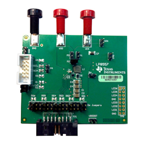
NOTE: If the part is enabled to any level of brightness or state and the program is closed, the LP8557 device will remain in the last controlled state. EVM Description The LP8557IEVM kit includes the main evaluation board, an LED loadboard, and the USB2ANY interface. LP8557IEVM User Guide SNVU371 – December 2013 Submit Documentation Feedback Copyright ©... - Page 3 EVM Description www.ti.com Main EVM Board Figure 2. LP8557IEVM Main Board SNVU371 – December 2013 LP8557IEVM User Guide Submit Documentation Feedback Copyright © 2013, Texas Instruments Incorporated...
- Page 4 EVM Description www.ti.com Figure 3. Current Sense Resistors LED Loadboard Figure 4. LED Loadboard LP8557IEVM User Guide SNVU371 – December 2013 Submit Documentation Feedback Copyright © 2013, Texas Instruments Incorporated...
-
Page 5: Kit Assembly
EVM Description www.ti.com Kit Assembly Figure 5. Kit Assembly SNVU371 – December 2013 LP8557IEVM User Guide Submit Documentation Feedback Copyright © 2013, Texas Instruments Incorporated... -
Page 6: Software Quick Start
Here are the fewest steps to light the LEDs. See the LP8557 datasheet for description of the device features. Figure 6. Software Quick Start LP8557IEVM User Guide SNVU371 – December 2013 Submit Documentation Feedback Copyright © 2013, Texas Instruments Incorporated... - Page 7 Main EVM Schematic www.ti.com Main EVM Schematic Figure 7. LP8557IEVM Schematic SNVU371 – December 2013 LP8557IEVM User Guide Submit Documentation Feedback Copyright © 2013, Texas Instruments Incorporated...
-
Page 8: Regulatory Compliance Information
Any exceptions to this are strictly prohibited and unauthorized by Texas Instruments unless user has obtained appropriate experimental/development licenses from local regulatory authorities, which is responsibility of user including its acceptable authorization. - Page 9 FCC Interference Statement for Class B EVM devices This equipment has been tested and found to comply with the limits for a Class B digital device, pursuant to part 15 of the FCC Rules. These limits are designed to provide reasonable protection against harmful interference in a residential installation. This equipment generates, uses and can radiate radio frequency energy and, if not installed and used in accordance with the instructions, may cause harmful interference to radio communications.
- Page 10 Also, please do not transfer this product, unless you give the same notice above to the transferee. Please note that if you could not follow the instructions above, you will be subject to penalties of Radio Law of Japan. Texas Instruments Japan Limited (address) 24-1, Nishi-Shinjuku 6 chome, Shinjuku-ku, Tokyo, Japan http://www.tij.co.jp...
- Page 11 FDA Class III or similar classification, then you must specifically notify TI of such intent and enter into a separate Assurance and Indemnity Agreement. Mailing Address: Texas Instruments, Post Office Box 655303, Dallas, Texas 75265 Copyright © 2013, Texas Instruments Incorporated...
-
Page 12: Important Notice
IMPORTANT NOTICE Texas Instruments Incorporated and its subsidiaries (TI) reserve the right to make corrections, enhancements, improvements and other changes to its semiconductor products and services per JESD46, latest issue, and to discontinue any product or service per JESD48, latest issue.
Need help?
Do you have a question about the LP8557IEVM and is the answer not in the manual?
Questions and answers