Advertisement
www.ti.com
EVM User's Guide: LP87694Q1EVM
LP8769x-Q1 Evaluation Module
Description
The LP87694Q1EVM board can be used to test,
demo, debug and configure one or more LP8769x-
Q1 power management ICs for automotive and
industrial applications. The device on board is
LP876940C0RQKRQ1 which has 1+1+1+1-phase
configuration for 4 different output voltage rails. The
EVM boards can be stacked for multi-PMIC operation
testing
Get Started
1. Order the EVM here.
2. Download the GUI
here
evaluation.
3. Download the supporting documents here.
4. Get additional material in functional safety and
design secure resources here.
SLVUCX5 – MAY 2024
Submit Document Feedback
for configuration and
Copyright © 2024 Texas Instruments Incorporated
Features
•
Input voltage range from 2.8V to 5.5V
•
Evaluation module can be powered with a bench
power supply or USB-C
•
On-board MSP432 to communicate with PMIC
using the GUI via USB-C cable
•
Board can be reworked to support other LP8769-
Q1 phase configurations
•
Boards can be stacked to support multi-PMIC
operation testing
Applications
•
Advanced driver assistance systems (ADAS)
•
Front camera
•
Surround view system ECU
•
Long range radar
•
Sensor fusion
•
Domain controller
Description
®
LP8769x-Q1 Evaluation Module
1
Advertisement
Table of Contents

Related Manuals for Texas Instruments LP8769-Q1 Series


Summary of Contents for Texas Instruments LP8769-Q1 Series
- Page 1 3. Download the supporting documents here. • Long range radar 4. Get additional material in functional safety and • Sensor fusion design secure resources here. • Domain controller SLVUCX5 – MAY 2024 LP8769x-Q1 Evaluation Module Submit Document Feedback Copyright © 2024 Texas Instruments Incorporated...
-
Page 2: Kit Contents
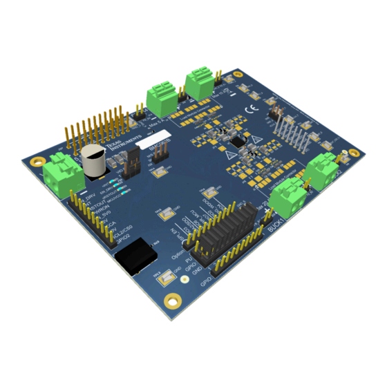
(NVM) configuration, and the hardware components associated with the configuration. Because of the configurable nature of both the part and the EVM, any EVM can be configured as a controller or target device. LP8769x-Q1 Evaluation Module SLVUCX5 – MAY 2024 Submit Document Feedback Copyright © 2024 Texas Instruments Incorporated... - Page 3 Please refer to LP8769-Q1 High Frequency Quad Step-Down DC-DC for more details. Figure 2-1 shows the LP8769x-Q1 EVM (controller). Figure 2-1. EVM (Top View) SLVUCX5 – MAY 2024 LP8769x-Q1 Evaluation Module Submit Document Feedback Copyright © 2024 Texas Instruments Incorporated...
-
Page 4: Terminal Blocks
J14, J16, J17, J19 FB_B1, FB_B2, FB_B3, Buck output voltage sense points. Secondary buck unused FBs are possible to FB_B4 use as voltage monitor as well. LP8769x-Q1 Evaluation Module SLVUCX5 – MAY 2024 Submit Document Feedback Copyright © 2024 Texas Instruments Incorporated... - Page 5 GPIO2, TRIG_WDG Closed Trigger signal for trigger mode watchdog. VIO Select must be 3.3V. GPIO7 or GPIO6 of the PMIC must be in the Alternative function to support the trigger TRIG_WDG, GPIO4 Closed mode watchdog signal. SLVUCX5 – MAY 2024 LP8769x-Q1 Evaluation Module Submit Document Feedback Copyright © 2024 Texas Instruments Incorporated...
- Page 6 IR voltage drop with heavy load currents. Align the VCCA/3.3V/5.0V jumper with the PMIC configuration. The default PMIC configuration supports the whole recommended VCCA voltage range. LP8769x-Q1 Evaluation Module SLVUCX5 – MAY 2024 Submit Document Feedback Copyright © 2024 Texas Instruments Incorporated...
- Page 7 EVMs to disable pull-up resistors. By using this stackup configuration, the power up sequences of one or more target EVMs always follow the controller. SLVUCX5 – MAY 2024 LP8769x-Q1 Evaluation Module Submit Document Feedback Copyright © 2024 Texas Instruments Incorporated...
-
Page 8: Dip Switches
PMIC/stacked use case. See the Table 2-7 for the descriptions of the switches. LP8769x-Q1 Evaluation Module SLVUCX5 – MAY 2024 Submit Document Feedback Copyright © 2024 Texas Instruments Incorporated... - Page 9 LED is on when nINT is low. LED is on when EN_DRV is high. LED is on when nRSTOUT is low. EVM power indicator. SLVUCX5 – MAY 2024 LP8769x-Q1 Evaluation Module Submit Document Feedback Copyright © 2024 Texas Instruments Incorporated...
- Page 10 And, on second target board GPIO2 and SPI_CS2 switches must be closed and so on. See Table 2-7 for details on S3 switch settings. Figure 2-6. Interface Settings for SPI Communication LP8769x-Q1 Evaluation Module SLVUCX5 – MAY 2024 Submit Document Feedback Copyright © 2024 Texas Instruments Incorporated...
- Page 11 FB pin to GND must be opened in this case (for example, R5/R6). 3 Software 3.1 GUI Tool Texas Instruments provides a GUI tool to enable, configure, and evaluate the various features of the LP8769x- Q1 with the EVM. Please refer to the GUI User's Guide for a more detailed description of this tool.
- Page 12 TP13 GPIO2 1.0k 47uF 47uF 47uF 47uF 47uF 47uF 5016 5016 TP16 TP14 5016 TP10 5016 5016 5016 5016 Figure 4-1. Schematic Page 1 LP8769x-Q1 Evaluation Module SLVUCX5 – MAY 2024 Submit Document Feedback Copyright © 2024 Texas Instruments Incorporated...
- Page 13 2.2µF 1.0k MCUVCC SPI_EN SPI_EN 2.85V PGND blue TLV73318PQDRVRQ1 PGND C135 C136 PGND 0.1uF 2.2µF PGND SDATA_SPMI SCLK_SPMI TPS60110PWPR Figure 4-2. Schematic Page 2 SLVUCX5 – MAY 2024 LP8769x-Q1 Evaluation Module Submit Document Feedback Copyright © 2024 Texas Instruments Incorporated...
-
Page 14: Pcb Layouts
Hardware Design Files www.ti.com 4.2 PCB Layouts Figure 4-3. Layout Top, Layer 1 Figure 4-4. Layout Ground, Layer 2 LP8769x-Q1 Evaluation Module SLVUCX5 – MAY 2024 Submit Document Feedback Copyright © 2024 Texas Instruments Incorporated... - Page 15 Hardware Design Files Figure 4-5. Layout Signal, Layer 3 Figure 4-6. Layout Signal, Layer 4 SLVUCX5 – MAY 2024 LP8769x-Q1 Evaluation Module Submit Document Feedback Copyright © 2024 Texas Instruments Incorporated...
- Page 16 Hardware Design Files www.ti.com Figure 4-7. Layout Ground, Layer 5 Figure 4-8. Layout Bottom LP8769x-Q1 Evaluation Module SLVUCX5 – MAY 2024 Submit Document Feedback Copyright © 2024 Texas Instruments Incorporated...
- Page 17 C122, C137, C138, 1210 C139, C140, C141, C142, C143, C144 D1, D2, D3, D5 Blue LB Q39G-L2N2-35-1 OSRAM LED, Blue, SMD BLUE 0603 LED SLVUCX5 – MAY 2024 LP8769x-Q1 Evaluation Module Submit Document Feedback Copyright © 2024 Texas Instruments Incorporated...
- Page 18 MOSFET, N-CH, 12V, 2.1A, YJC0003A YJC0003A (PICOSTAR-3) R1, R3, R4, R7, CRCW04020000Z0ED Vishay-Dale RES, 0, 5%, 0.063 W, AEC-Q200 Grade 0, R12, R14, R16, 0402 R85, R87, R88, LP8769x-Q1 Evaluation Module SLVUCX5 – MAY 2024 Submit Document Feedback Copyright © 2024 Texas Instruments Incorporated...
- Page 19 TP10, TP11, TP12, TP13, TP14, TP15, TP16 LP876940C0RKQRQ1 Texas Instruments High Frequency Quad Step-Down DC-DC VQFN-HR32 LM2901AVQPWRQ1 Texas Instruments AEC-Q100 Quad Comparator, PW0014A PW0014A (TSSOP-14) SLVUCX5 – MAY 2024 LP8769x-Q1 Evaluation Module Submit Document Feedback Copyright © 2024 Texas Instruments Incorporated...
- Page 20 5-SC70 -40 to 125 TPS22919DCKR Texas Instruments 5.5V, 1.5A, 100-mohm Load Switch DCK0006A with Output Discharge, DCK0006A (SOT- SC70-6) NX3225SA-25.000M-STD- CRYSTAL 25.0000MHZ 8PF SMD SMT_XTAL_3MM2_2M CRS-2 LP8769x-Q1 Evaluation Module SLVUCX5 – MAY 2024 Submit Document Feedback Copyright © 2024 Texas Instruments Incorporated...
- Page 21 5.2 Trademarks USB-C ® and USB Type-C ® are registered trademarks of USB Implementers Forum. All trademarks are the property of their respective owners. SLVUCX5 – MAY 2024 LP8769x-Q1 Evaluation Module Submit Document Feedback Copyright © 2024 Texas Instruments Incorporated...
- Page 22 STANDARD TERMS FOR EVALUATION MODULES Delivery: TI delivers TI evaluation boards, kits, or modules, including any accompanying demonstration software, components, and/or documentation which may be provided together or separately (collectively, an “EVM” or “EVMs”) to the User (“User”) in accordance with the terms set forth herein.
- Page 23 www.ti.com Regulatory Notices: 3.1 United States 3.1.1 Notice applicable to EVMs not FCC-Approved: FCC NOTICE: This kit is designed to allow product developers to evaluate electronic components, circuitry, or software associated with the kit to determine whether to incorporate such items in a finished product and software developers to write software applications for use with the end product.
- Page 24 www.ti.com Concernant les EVMs avec antennes détachables Conformément à la réglementation d'Industrie Canada, le présent émetteur radio peut fonctionner avec une antenne d'un type et d'un gain maximal (ou inférieur) approuvé pour l'émetteur par Industrie Canada. Dans le but de réduire les risques de brouillage radioélectrique à...
- Page 25 www.ti.com EVM Use Restrictions and Warnings: 4.1 EVMS ARE NOT FOR USE IN FUNCTIONAL SAFETY AND/OR SAFETY CRITICAL EVALUATIONS, INCLUDING BUT NOT LIMITED TO EVALUATIONS OF LIFE SUPPORT APPLICATIONS. 4.2 User must read and apply the user guide and other available documentation provided by TI regarding the EVM prior to handling or using the EVM, including without limitation any warning or restriction notices.
- Page 26 Notwithstanding the foregoing, any judgment may be enforced in any United States or foreign court, and TI may seek injunctive relief in any United States or foreign court. Mailing Address: Texas Instruments, Post Office Box 655303, Dallas, Texas 75265 Copyright © 2023, Texas Instruments Incorporated...
- Page 27 TI products. TI’s provision of these resources does not expand or otherwise alter TI’s applicable warranties or warranty disclaimers for TI products. TI objects to and rejects any additional or different terms you may have proposed. IMPORTANT NOTICE Mailing Address: Texas Instruments, Post Office Box 655303, Dallas, Texas 75265 Copyright © 2024, Texas Instruments Incorporated...
Need help?
Do you have a question about the LP8769-Q1 Series and is the answer not in the manual?
Questions and answers