Planet IGS-4215-8UP4X User Manual
Industrial l2/l4 8-port 10/100/1000t+4-port 10g sfp+ managed ethernet switch
Hide thumbs
Also See for IGS-4215-8UP4X:
- Quick installation manual (18 pages) ,
- Quick installation manual (15 pages) ,
- Quick installation manual (17 pages)

Subscribe to Our Youtube Channel
Related Manuals for Planet IGS-4215-8UP4X


Summary of Contents for Planet IGS-4215-8UP4X
- Page 1 User’s Manual of IGS-4215-8T4X_IGS-4215-8UP4X Industrial L2/L4 8-Port 10/100/1000T+ 4-Port 10G SFP+ Managed Ethernet Switch IGS-4215-8T4X IGS-4215-8UP4X...
- Page 2 PLANET is a registered trademark of PLANET Technology Corp. All other trademarks belong to their respective owners. Disclaimer PLANET Technology does not warrant that the hardware will work properly in all environments and applications, and makes no warranty and representation, either implied or expressed, with respect to the quality, performance, merchantability, or fitness for a particular purpose.
-
Page 3: Table Of Contents
3.2 Management Access Overview ........................48 3.3 Administration Console ..........................49 3.4 Web Management ............................50 3.5 SNMP-based Network Management ......................51 3.6 PLANET Smart Discovery Utility ........................ 51 4. WEB CONFIGURATION ...................... 53 4.1 Main Web Page ............................. 56 4.1.1 Save Button ................................58 4.1.2 Configuration Manager ............................. - Page 4 User’s Manual of IGS-4215-8T4X_IGS-4215-8UP4X 4.2.2 IP Configurations ..............................62 4.2.3 IPv6 Configuration ..............................64 4.2.4 User Configuration ..............................66 4.2.5 Fault Alarm Configuration ............................67 4.2.6 Digital Input Digital Output ............................68 4.2.7 Time Settings ................................70 4.2.7.1 System Time............................... 70 4.2.7.2 SNTP Server Settings ............................
- Page 5 User’s Manual of IGS-4215-8T4X_IGS-4215-8UP4X 4.3.10 SFP Module Information ............................120 4.3.10.1 SFP Module Status ............................120 4.3.10.2 SFP Module Detail Status ..........................121 4.4 Link Aggregation ............................122 4.4.1 LAG Setting ................................124 4.4.2 LAG Management ..............................125 4.4.3 LAG Port Setting ..............................126 4.4.4 LACP Setting ................................
- Page 6 User’s Manual of IGS-4215-8T4X_IGS-4215-8UP4X 4.8.3 IGMP Static Group ..............................191 4.8.4 IGMP Group Table ..............................192 4.8.5 IGMP Router Setting ............................... 193 4.8.6 IGMP Router Table ..............................194 4.8.7 IGMP Forward All ..............................195 4.8.8 IGMP Snooping Statics ............................196 4.8.9 IGMP Filter Setting ..............................
- Page 7 User’s Manual of IGS-4215-8T4X_IGS-4215-8UP4X 4.12.4.1 Ingress Bandwidth Control ..........................239 4.12.4.2 Egress Bandwidth Control ..........................240 4.12.4.3 Egress Queue ..............................241 4.12.5 Storm Control ................................ 242 4.12.5.1 Global Setting ..............................242 4.12.5.2 Port Setting..............................243 4.12.6 Voice VLAN ................................245 4.12.6.1 Introduction to Voice VLAN..........................
- Page 8 User’s Manual of IGS-4215-8T4X_IGS-4215-8UP4X 4.13.6.9 Option82 Port Setting ............................. 289 4.13.6.10 Option82 Circuit-ID Setting ........................... 291 4.13.7 Dynamic ARP Inspection ............................292 4.13.7.1 Global Setting ..............................292 4.13.7.2 VLAN Setting ..............................293 4.13.7.3 Port Setting..............................294 4.13.7.4 Statistics ................................. 296 4.13.7.5 ARP Rate Limit ...............................
- Page 9 User’s Manual of IGS-4215-8T4X_IGS-4215-8UP4X 5. SWITCH OPERATION ....................... 350 5.1 Address Table ............................. 350 5.2 Learning ..............................350 5.3 Forwarding & Filtering ..........................350 5.4 Store-and-Forward ............................. 350 5.5 Auto-Negotiation ............................350 6. TROUBLESHOOTING ....................... 351 APPENDIX A Switch's RJ45 Pin Assignments ..............352 A.1 1000Mbps, 1000BASE-T..........................
-
Page 10: Introduction
1. INTRODUCTION Thank you for purchasing PLANET IGS-4215 Industrial Managed Switch series, which comes with multiple Gigabit Ethernet copper ports and 10G SFP+ fiber optic ports as well as robust Layer 2 and Layer 4 features. The description of the switches is... -
Page 11: Product Description
1.2 Product Description Budget-friendly Industrial L2/L4 Switch with PoE Capability Tailored for the challenges of heavy industrial environments, the IGS-4215-8T4X and IGS-4215-8UP4X stand out as PLANET's latest DIN-rail L2/L4 Managed Gigabit switches. The IGS-4215-8T4X, a budget-friendly option, delivers versatile features, including IPv6/IPv4 dual stack management and a built-in L2/L4 Gigabit switching engine. - Page 12 The IGS-4215-8UP4X can be configured to monitor connected PD (powered device) status in real time via ping action. Once the PD stops working and responding, the IGS-4215-8UP4X will resume the PoE port power and bring the PD back to work. It will greatly enhance the network reliability through the PoE port resetting the PD’s power source and reducing the...
- Page 13 Scheduled Power Recycling The IGS-4215-8UP4X allows each of the connected PoE IP cameras or PoE wireless access points to reboot at a specified time each week. Therefore, it will reduce the chance of IP camera or AP crash resulting from buffer overflow.
- Page 14 Digital Input and Digital Output for External Alarm The IGS-4215-8UP4X and IGS-4215-8T4X support Digital Input and Digital Output through a terminal block located on its upper panel. This external alarm enables users to use Digital Input to detect and log external device status (such as door intrusion detector), and send event alarm to the administrators.
- Page 15 User’s Manual of IGS-4215-8T4X_IGS-4215-8UP4X Robust Protection The IGS-4215 Series provides contact discharge of ±6KV DC and air discharge of ±8KV DC for Ethernet ESD protection. It also supports ±4KV surge immunity to improve product stability and protects users’ networks from devastating ESD attacks, making sure the flow of operation does not fluctuate.
- Page 16 Enhancing Network Security PLANET IGS-4215 Series offers comprehensive IPv4/IPv6 Layer 2 to Layer 4 Access Control List (ACL) for enforcing security to the edge. It can be used to restrict network access by denying packets based on source and destination IP address, TCP/UDP ports or defined typical network applications.
- Page 17 Remote Management Solution PLANET's Universal Network Management System (UNI-NMS) and CloudViewerPro app provide robust support for IT staff in effectively managing and monitoring all network devices, including the IGS-4215 series, from remote locations. Tailored for deployment in both enterprises and industries where the IGS-4215 series is utilized remotely, these systems enable the identification of bugs or faulty conditions without the need for on-site visits.
-
Page 18: How To Use This Manual
User’s Manual of IGS-4215-8T4X_IGS-4215-8UP4X 1.3 How to Use This Manual This User Manual is structured as follows: Section 2, INSTALLATION The section explains the functions of the Switch and how to physically install the Industrial Managed Switch. Section 3, SWITCH MANAGEMENT The section contains the information about the software function of the Industrial Managed Switch. -
Page 19: Product Features
1.4 Product Features Physical Port ■ 8 10/100/1000BASE-T Gigabit Ethernet RJ45 ports ■ 8 ports with IEEE 802.3bt PoE++ injector function (PoE functionality is exclusive in the IGS-4215-8UP4X model) ■ 4 10GBASE-SR/LR SFP+ slots, backward compatible with 100/1G/2.5GBASE-X SFP ■ One USB Type C console interface for basic management and setup Power over Ethernet (PoE functionality is exclusive in the IGS-4215-8UP4X model) ■... - Page 20 User’s Manual of IGS-4215-8T4X_IGS-4215-8UP4X Switching ■ Hardware-based 10/100Mbps (half/full duplex), 1000Mbps (full duplex), auto-negotiation and auto MDI/MDI-X ■ IEEE 802.3x flow control for full duplex operation and back pressure for half duplex operation ■ 16K MAC address table size ■ 10K jumbo frame ■...
- Page 21 SFP-DDM (Digital Diagnostic Monitor) Link Layer Discovery Protocol (LLDP) Protocol and LLDP-MED Event message logging to remote syslog server PLANET Smart Discovery Utility for deployment management PLANET NMS system and CloudViewer/CloudViewerPro for deployment management * Future feature...
-
Page 22: Product Specifications
User’s Manual of IGS-4215-8T4X_IGS-4215-8UP4X 1.5 Product Specifications Product IGS-4215-8UP4X IGS-4215-8T4X Hardware Specifications 8 10/100/1000BASE-T RJ45 8 10/100/1000BASE-T RJ45 auto-MDI/MDI-X Copper Ports auto-MDI/MDI-X ports (Ports 1 to 8) ports (Ports 1 to 8) 8 ports with 802.3bt PoE++ injector PoE Injector Port... - Page 23 User’s Manual of IGS-4215-8T4X_IGS-4215-8UP4X I/O (Red) I/O (Red) Per 10/100/1000T RJ45 PoE++ Ports: Per 10/100/1000T RJ45 1000 LNK/ACT (Green) 1000 LNK/ACT (Green) 10/100 LNK/ACT (Amber) 802.3bt (Green) Down Down 10/100 LNK/ACT (Amber) 802.3at (Amber) PoE Usage: 90/180/270/360W (Amber) Per 10G SFP Interface: Per 10G SFP Interface: 1G/2.5G LNK/ACT (Green) 1G/2.5G LNK/ACT (Green)
- Page 24 User’s Manual of IGS-4215-8T4X_IGS-4215-8UP4X 802.3bt Type 4 PDs Max. Number of 60W 802.3bt Type 3 PDs Max. Number of 30W 802.3at Type 2 PDs PoE Management Functions PD Alive Check Scheduled Power Recycling PoE Schedule PoE Management PoE Usage Monitoring PoE Extension Standard/Legacy/Force Enhanced PoE Mode...
- Page 25 SSHv2, TLSv1.2, SNMP v3 Interfaces Firmware upgrade by HTTP/TFTP protocol through Ethernet network Configuration upload/download through HTTP/TFTP LLDP protocol System Management SNTP PLANET Smart Discovery Utility PLANET NMS System/CloudViewer/CloudViewerPro Remote/Local Syslog Event Management System log RFC 1213 MIB-II RFC 1213 MIB-II...
- Page 26 User’s Manual of IGS-4215-8T4X_IGS-4215-8UP4X Standards Conformance Regulatory FCC Part 15 Class A, CE Compliance IEC 60068-2-32 (free fall) Stability Testing IEC 60068-2-27 (shock) IEC 60068-2-6 (vibration) IEEE 802.3 10BASE-T IEEE 802.3 10BASE-T IEEE 802.3u 100BASE-TX/100BASE-FX IEEE 802.3u 100BASE-TX/100BASE-FX IEEE 802.3z Gigabit SX/LX IEEE 802.3z Gigabit SX/LX IEEE 802.3ab Gigabit 1000BASE-T IEEE 802.3ab Gigabit 1000BASE-T...
-
Page 27: Installation
Industrial Managed Switch, familiarize yourself with its display indicators and ports. Front panel illustrations in this chapter display the unit LED indicators. Before connecting any network device to the Industrial Managed Switch, please read this chapter completely. Model Name IGS-4215-8T4X IGS-4215-8UP4X Item 10/100/1000BASE-T Copper 10GBASE-X SFP+ Power over Ethernet Standard IEEE 802.3bt PoE++... -
Page 28: Physical Dimensions
User’s Manual of IGS-4215-8T4X_IGS-4215-8UP4X 2.1.1 Physical Dimensions IGS-4215-8T4X Dimensions (W x D x H) : 76 x 135 x 152 mm... - Page 29 User’s Manual of IGS-4215-8T4X_IGS-4215-8UP4X IGS-4215-8UP4X Dimensions (W x D x H) : 76 x 135 x 152 mm...
-
Page 30: Switch Front Panel
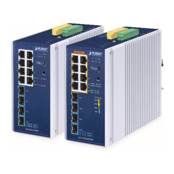
Figure 2-1-2 shows the front panels of the Industrial Managed Switch series. Front Panel IGS-4215-8T4X IGS-4215-8UP4X Figure 2-1-2: IGS-4215-8T4X/IGS-4215-8UP4X Front Panels Gigabit TP Interface 10/100/1000BASE-T copper, RJ45 twisted-pair: Up to 100 meters. 10GBASE-X SFP+ Slots 1G/2.5G/10GBASE-SR/LR mini-GBIC slot for SFP+ (Small Factor Pluggable Plus) transceiver module support distance from 300 meters (multi-mode fiber) to 10 kilometers (single mode fiber). - Page 31 User’s Manual of IGS-4215-8T4X_IGS-4215-8UP4X Reset Button On the left of the front panel, the reset button is designed to reboot the Industrial Managed Switch without turning off and on the power. The following is the summary table of reset button functions: Reset button Reset Button Function...
-
Page 32: Led Indications
Figure 2-1-3a and Figure 2-1-3b shows the LED indications of these Industrial Managed Switches. IGS-4215-8UP4X IGS-4215-8T4X Figure 2-1-3a: IGS-4215-8T4X Figure 2-1-3b: IGS-4215-8UP4X System Color Function PWR 1 Green Lights to indicate DC power input 1 has power. - Page 33 To indicate the port is running at 10Mbps, 100Mbps and is Down 10/100 LNK/ACT Amber Blinks successfully established. Per 10/100/1000BASE-T, 802.3bt RJ45 Port (Port 1 to 8) for IGS-4215-8UP4X Color Function Direction To indicate the port is running at 1000Mbps and is successfully 1000 LNK/ACT Green Lights established.
-
Page 34: Switch Upper Panel
Figures 2-1-4a and Figures 2-1-4b show the upper panels of the Industrial Managed Switch series. IGS-4215-8T4X Figure 2-1-4a: Industrial Managed Switch Upper Panel. IGS-4215-8UP4X Figure 2-1-4b: Industrial Managed Switch Upper Panel. -
Page 35: Wiring The Power Inputs
Pin 2/6 The wire gauge for the terminal block should be in the range from 12 to 24 AWG. Please check the wire AWG Ampere specification before connecting PLANET Industrial Managed PoE Switch. For optimal power load balancing during dual power input operations, PWR1 and PWR2 must supply the same DC voltage. -
Page 36: Wiring The Fault Alarm Contact
The 6-contact terminal block connector on the rear panel of IGS Series is used for Digital Input and Digital Output. Please follow the steps below to insert wire. The IGS-4215-8T4X and IGS-4215-8UP4X offers two DI and DO groups. 1 and 2 are DI groups; 3 and 4 are DO groups; and 5 and 6 are GND (ground). - Page 37 Figure 2-1-7c Wiring DI0 and DI1 to Open Detector There are two Digital Output groups for you to sense IGS-4215-8T4X/IGS-4215-8UP4X port failure or power failure and send a high or low signal to external device. The following topology shows how to wire DO0 and DO1.
-
Page 38: Installing The Industrial Managed Switch
User’s Manual of IGS-4215-8T4X_IGS-4215-8UP4X 2.2 Installing the Industrial Managed Switch This section describes how to install your Industrial Managed Switch and make connections to the Industrial Managed Switch. Please read the following topics and perform the procedures in the order being presented. To install your Industrial Managed Switch on a desktop or shelf, simply complete the following steps. -
Page 39: Din-Rail Mounting
User’s Manual of IGS-4215-8T4X_IGS-4215-8UP4X 2.2.2 DIN-rail Mounting This section describes how to install the Industrial Managed Switch. There are two methods to install the Industrial Managed Switch -- DIN-rail mounting and wall-mount plate mounting. Please read the following topics and perform the procedures in the order being presented. - Page 40 User’s Manual of IGS-4215-8T4X_IGS-4215-8UP4X Step 3: Check whether the DIN rail is tightly on the track. Please refer to the following procedures to remove the Industrial Managed Switch from the track. Step 4: Lightly remove the DIN rail from the track.
-
Page 41: Wall-Mount Plate Mounting
User’s Manual of IGS-4215-8T4X_IGS-4215-8UP4X 2.2.3 Wall-mount Plate Mounting To install the Industrial Managed Switch on the wall, please follow the instructions below. Follow all the DIN-rail installation steps as shown in the example. Step 1: Remove the DIN rail from the Industrial Managed Switch. Use the screwdriver to loosen the screws to remove the DIN rail. -
Page 42: Installing The Sfp/Sfp+ Transceiver
Approved PLANET SFP Transceivers PLANET Industrial Managed Switch supports 100/1000/2.5G/10G dual mode with both single mode and multi-mode SFP transceivers. The following list of approved PLANET SFP transceivers is correct at the time of publication: Fast Ethernet Transceiver (100BASE-X SFP) Connector... - Page 43 User’s Manual of IGS-4215-8T4X_IGS-4215-8UP4X Fast Ethernet Transceiver (100BASE-BX, Single Fiber Bi-directional SFP) Connector Wavelength Wavelength Model Speed (Mbps) Fiber Mode Distance Operating Temp. Interface (TX) (RX) 0 ~ 60 degrees C MFB-FA20 WDM(LC) Single Mode 20km 1310nm 1550nm 1310nm 0 ~ 60 degrees C MFB-FB20 WDM(LC) Single Mode 20km...
- Page 44 User’s Manual of IGS-4215-8T4X_IGS-4215-8UP4X 2.5 Gigabit Ethernet Transceiver (2500BASE-X SFP) Speed Connector Wavelength Wavelength Model Fiber Mode Distance Operating Temp. (Mbps) Interface (TX) (RX) MGB-2GTSR -40 ~ 85°C 2500 Multi-mode 300m 850nm MGB-2GTLR2 -40 ~ 85°C 2500 Single mode 1310nm MGB-2GTLA20 -40 ~ 85°C 2500...
- Page 45 1270nm -40 ~ 85°C It is recommended to use PLANET SFPs on the Industrial Managed Switch. If you insert an SFP transceiver that is not supported, the Industrial Managed Switch might not recognize it. Please choose the SFP transceiver which can be operated in the temperature range of -40~75 degrees C.
-
Page 46: Removing The Sfp/Sfp+ Transceiver
User’s Manual of IGS-4215-8T4X_IGS-4215-8UP4X 2.2.5 Removing the SFP/SFP+ Transceiver Make sure there is no network activity by consulting or checking with the network administrator. Or through the management interface of the switch/converter (if available) to disable the port in advance. Remove the fiber optic cable gently. -
Page 47: Switch Management
User’s Manual of IGS-4215-8T4X_IGS-4215-8UP4X 3. SWITCH MANAGEMENT This chapter explains the methods that you can use to configure management access to the Industrial Managed Switch. It describes the types of management applications and the communication and management protocols that deliver data between your management device (workstation or personal computer) and the system. -
Page 48: Management Access Overview
User’s Manual of IGS-4215-8T4X_IGS-4215-8UP4X 3.2 Management Access Overview The Industrial Managed Switch gives you the flexibility to access and manage it using any or all of the following methods: An administration console Web browser interface An external SNMP-based network management application The administration console and Web browser interfaces are embedded in the Industrial Managed Switch software and are available for immediate use. -
Page 49: Administration Console
User’s Manual of IGS-4215-8T4X_IGS-4215-8UP4X 3.3 Administration Console The administration console is an internal, character-oriented, and command line user interface for performing system administration such as displaying statistics or changing option settings. Using this method, you can view the administration console from a terminal, personal computer, Apple Macintosh, or workstation connected to the Industrial Managed Switch's console port. -
Page 50: Web Management
User’s Manual of IGS-4215-8T4X_IGS-4215-8UP4X 3.4 Web Management The Industrial Managed Switch offers management features that allow users to manage the Industrial Managed Switch from anywhere on the network through a standard browser such as Microsoft Edge, Firefox or Google Chrome. After you set up your IP address for the switch, you can access the Industrial Managed Switch's Web interface applications directly in your Web browser by entering the IP address of the Industrial Managed Switch. -
Page 51: Snmp-Based Network Management
3.6 PLANET Smart Discovery Utility For easily listing the Industrial Managed Switch in your Ethernet environment, the Planet Smart Discovery Utility which usrs can download from PLANET’s website is an ideal solution. The following installation instructions are to guide you to running the Planet Smart Discovery Utility. - Page 52 To click the “Control Packet Force Broadcast” function, it allows you to assign a new setting value to the Web Smart Switch under a different IP subnet address. Press the “Connect to Device” button and the Web login screen appears in Figure 3-1-4. Press the “Exit” button to shut down the Planet Smart Discovery Utility.
-
Page 53: Web Configuration
User’s Manual of IGS-4215-8T4X_IGS-4215-8UP4X 4. WEB CONFIGURATION This section introduces the configuration and functions of the Web-based management. About Web-based Management The Industrial Managed Switch provides advanced management capabilities, enabling remote control and monitoring via standard web browsers like Microsoft Edge, Firefox, and Google Chrome. This accessibility allows users to efficiently manage the switch from any internet-connected location. - Page 54 User’s Manual of IGS-4215-8T4X_IGS-4215-8UP4X Logging on to the switch To access the Web interface of the Industrial Managed Switch, use any of the recommended web browsers (Microsoft Edge, Firefox, or Google Chrome) and enter the switch's default IP address. This IP address is pre-configured at the factory and allows initial setup and configuration through the browser-based management system.
- Page 55 User’s Manual of IGS-4215-8T4X_IGS-4215-8UP4X After logging in, you will be prompted to change the initial password to a permanent one. Figure 4-1-3: Create a New Password Once the password change is complete, re-enter the web interface using your new password and the main screen appears as Figure 4-1-4 shows.
-
Page 56: Main Web Page
User’s Manual of IGS-4215-8T4X_IGS-4215-8UP4X 4.1 Main Web Page The Industrial Managed Switch provides a Web-based browser interface for configuring and managing it. This interface allows you to access the Industrial Managed Switch using the Web browser of your choice. This chapter describes how to use the Industrial Managed Switch’s Web browser interface to configure and manage it. - Page 57 User’s Manual of IGS-4215-8T4X_IGS-4215-8UP4X Main Menu Using the onboard Web agent, you can define system parameters, manage and control the Industrial Managed Switch, and all its ports, or monitor network conditions. Via the Web-Management, the administrator can set up the Industrial Managed Switch by selecting the functions those listed in the Main Function.
-
Page 58: Save Button
User’s Manual of IGS-4215-8T4X_IGS-4215-8UP4X 4.1.1 Save Button This save button allows you to save the running/startup/backup configuration or reset switch in default parameter. The screen in Figure 4-1-6 appears. Figure 4-1-6: Save Button Screenshot The page includes the following fields: Object Description ... -
Page 59: Saving Configuration
User’s Manual of IGS-4215-8T4X_IGS-4215-8UP4X 4.1.2.1 Saving Configuration In the Industrial Managed Switch, the running configuration file stores in the RAM. In the current version, the running configuration sequence of running-config can be saved from the RAM to FLASH by ”Save Configurations to FLASH” function, so that the running configuration sequence becomes the startup configuration file, which is called Save Configuration. -
Page 60: System
SNMP Management Configure SNMP on this page. Remote Management Configure subscription settings for PLANET's NMS or the CloudViewerPro mobile app. SMTP Configure SMTP settings. 4.2.1 System Information The System Info page provides information for the current device information. System Info page helps a switch administrator to identify the hardware MAC address, software version and system uptime. - Page 61 User’s Manual of IGS-4215-8T4X_IGS-4215-8UP4X The page includes the following fields: Object Description System Name Display the current system name System Location Display the current system location System Contact Display the current system contact MAC Address The MAC address of this Industrial Managed Switch. ...
-
Page 62: Ip Configurations
User’s Manual of IGS-4215-8T4X_IGS-4215-8UP4X 4.2.2 IP Configurations The IP Configuration includes the IP Address, Subnet Mask and Gateway. The configured column is used to view or change the IP configuration. Fill out the IP Address, Subnet Mask and Gateway for the device. The screens in Figure 4-2-2-1 Figure 4-2-2-2... - Page 63 User’s Manual of IGS-4215-8T4X_IGS-4215-8UP4X Figure 4-2-2-2: IP Information Page Screenshot The page includes the following fields: Object Description DHCP State Displays the current DHCP state. IP Address Displays the current IP address. Subnet Mask Displays the current subnet mask. ...
-
Page 64: Ipv6 Configuration
User’s Manual of IGS-4215-8T4X_IGS-4215-8UP4X 4.2.3 IPv6 Configuration The IPv6 Configuration includes Auto Configuration, IPv6 Address and Gateway. The configured column is used to view or change the IPv6 configuration. Fill out the Auto Configuration, IPv6 Address and Gateway for the device. The screens in Figure 4-2-3-1 Figure 4-2-3-2... - Page 65 User’s Manual of IGS-4215-8T4X_IGS-4215-8UP4X Figure 4-2-3-2: IPv6 Information Page Screenshot The page includes the following fields: Object Description Auto Configuration Displays the current auto configuration state IPv6-in-Use Address Displays the currently-used IPv6 address IPv6-in-Use Router Displays the currently-used gateway ...
-
Page 66: User Configuration
User’s Manual of IGS-4215-8T4X_IGS-4215-8UP4X 4.2.4 User Configuration This page provides an overview of the current users and privilege type. Currently the only way to login as another user on the Web server is to close and reopen the browser. After the setup is completed, please press the “Apply” button to take effect. Please login Web interface with a new user name and password;... -
Page 67: Fault Alarm Configuration
User’s Manual of IGS-4215-8T4X_IGS-4215-8UP4X 4.2.5 Fault Alarm Configuration This Page facilitates a fault alarm controlling the switch. The Fault Alarm Control Configuration screen in Figure 4-2-5-1 appears. Figure 4-2-5-1: Fault Alarm Control Configuration Page Screenshot The page includes the following fields: Object Description ... -
Page 68: Digital Input Digital Output
User’s Manual of IGS-4215-8T4X_IGS-4215-8UP4X 4.2.6 Digital Input Digital Output Digital Input allows user to log external device (such as industrial cooler) dead or alive or something else. System will log a user customized message into system log and syslog, and issue SNMP trap. Digital Output allows user to monitor the switch port and power, and let system issue a high or low signal to an external device (such as alarm) when the monitor port or power has failed. - Page 69 User’s Manual of IGS-4215-8T4X_IGS-4215-8UP4X The page includes the following fields: Object Description Check the Enable checkbox to enable Digital Input function. Enable Uncheck the Enable checkbox to disable Digital Input function. As Digital Input: DI Condition Allows user to select High to Low or Low to High. This means a signal received by system is from High to Low or From Low to High.
-
Page 70: Time Settings
User’s Manual of IGS-4215-8T4X_IGS-4215-8UP4X 4.2.7 Time Settings 4.2.7.1 System Time Configure SNTP on this page. SNTP is an acronym for Simple Network Time Protocol, a network protocol for synchronizing the clocks of computer systems. You can specify SNTP Servers and set GMT Time zone. The SNTP Configuration screens in Figure 4-2-7-1 Figure 4-2-7-2 appear. - Page 71 User’s Manual of IGS-4215-8T4X_IGS-4215-8UP4X Daylight Saving Time This is used to set the clock forward or backward according to the configurations set below for a defined Daylight Saving Time duration. Select 'Disable' to disable the Daylight Saving Time configuration. Select 'Recurring' and configure the Daylight Saving Time duration to repeat the configuration every year.
- Page 72 User’s Manual of IGS-4215-8T4X_IGS-4215-8UP4X Figure 4-2-7-2: Time Information Page Screenshot The page includes the following fields: Object Description Current Data/Time Displays the current data/time. SNTP Displays the current SNTP state. Time Zone Displays the current time zone. ...
-
Page 73: Sntp Server Settings
User’s Manual of IGS-4215-8T4X_IGS-4215-8UP4X 4.2.7.2 SNTP Server Settings The SNTP Server Configuration screens in Figure 4-2-7-3 Figure 4-2-7-4 appear. Figure 4-2-7-3: SNTP Setup Page Screenshot The page includes the following fields: Object Description SNTP Server Address Type the IP address or domain name of the SNTP server. ... -
Page 74: Log Management
User’s Manual of IGS-4215-8T4X_IGS-4215-8UP4X 4.2.8 Log Management The Industrial Managed Switch log management is provided here. The local logs allow you to configure and limit system messages that are logged to flash or RAM memory. The default is for event levels 0 to 3 to be logged to flash and levels 0 to 6 to be logged to RAM. -
Page 75: Local Log
User’s Manual of IGS-4215-8T4X_IGS-4215-8UP4X 4.2.8.2 Local Log The switch system local log information is provided here. The local Log screens in Figure 4-2-8-3 Figure 4-2-8-4 appear. Figure 4-2-8-3: Local Log Target Setting Page Screenshot The page includes the following fields: Object Description ... -
Page 76: Remote Syslog
User’s Manual of IGS-4215-8T4X_IGS-4215-8UP4X 4.2.8.3 Remote Syslog Configure remote syslog on this page. The Remote Syslog page allows you to configure the logging of messages that are sent to syslog servers or other management stations. You can also limit the event messages sent to only those messages below a specified level. - Page 77 User’s Manual of IGS-4215-8T4X_IGS-4215-8UP4X The page includes the following fields: Object Description Server Address Provides the remote syslog IP address of this switch. Server Port Provides the port number of remote syslog server. Default Port no.: 514 Severity The severity of the local log entry.
-
Page 78: Log Message
User’s Manual of IGS-4215-8T4X_IGS-4215-8UP4X 4.2.8.4 Log Message The switch log view is provided here. The Log View screens in Figure 4-2-8-7, Figure 4-2-8-8 Figure 4-2-8-9 appear. Figure 4-2-8-7: Log Information Select Page Screenshot The page includes the following fields: Object Description ... - Page 79 User’s Manual of IGS-4215-8T4X_IGS-4215-8UP4X The page includes the following fields: Object Description Target Displays the current log target. Severity Displays the current log severity. Category Displays the current log category. Total Entries Displays the current log entries. Figure 4-2-8-9: Logging Messages Page Screenshot The page includes the following fields: Object...
-
Page 80: Snmp Management
User’s Manual of IGS-4215-8T4X_IGS-4215-8UP4X 4.2.9 SNMP Management 4.2.9.1 SNMP Overview The Simple Network Management Protocol (SNMP) is an application layer protocol that facilitates the exchange of management information between network devices. It is part of the Transmission Control Protocol/Internet Protocol (TCP/IP) protocol suite. -
Page 81: Snmp Setting
User’s Manual of IGS-4215-8T4X_IGS-4215-8UP4X 4.2.9.2 SNMP Setting Configure SNMP setting on this page. The SNMP System global setting screens in Figure 4-2-9-1 & Figure 4-2-9-2 appear. Figure 4-2-9-1: SNMP Global Setting Page Screenshot The page includes the following fields: Object Description ... -
Page 82: Snmp View
User’s Manual of IGS-4215-8T4X_IGS-4215-8UP4X 4.2.9.3 SNMP View Configure SNMPv3 view table on this page. The entry index keys are View Name and OID Subtree. The SNMPv3 View Table Setting screens in Figure 4-2-9-3 Figure 4-2-9-4 appear. Figure 4-2-9-3: SNMPv3 View Table Setting Page Screenshot The page includes the following fields: Object Description... -
Page 83: Snmp Access Group
User’s Manual of IGS-4215-8T4X_IGS-4215-8UP4X 4.2.9.4 SNMP Access Group Configure SNMPv3 access group on this page. The entry index keys are Group Name, Security Model and Security Level. The SNMPv3 Access Group Setting screens in Figure 4-2-9-5 Figure 4-2-9-6 appear. Figure 4-2-9-5: SNMPv3 Access Group Setting Page Screenshot The page includes the following fields: Object Description... - Page 84 User’s Manual of IGS-4215-8T4X_IGS-4215-8UP4X Figure 4-2-9-6: SNMP View Table Status Page Screenshot The page includes the following fields: Object Description Group Name Displays the current SNMP access group name. Security Model Displays the current security model. Security Level Displays the current security level.
-
Page 85: Snmp Community
User’s Manual of IGS-4215-8T4X_IGS-4215-8UP4X 4.2.9.5 SNMP Community Configure SNMP Community on this page. The SNMP Community screens in Figure 4-2-9-7 Figure 4-2-9-8 appear. Figure 4-2-9-7: Community Setting Page Screenshot The page includes the following fields: Object Description Community Name Indicates the community read/write access string to permit access to SNMP agent. -
Page 86: Snmp User
User’s Manual of IGS-4215-8T4X_IGS-4215-8UP4X 4.2.9.6 SNMP User Configure SNMPv3 users table on this page. Each SNMPv3 user is defined by a unique name. Users must be configured with a specific security level and assigned to a group. The SNMPv3 group restricts users to a specific read, write, and notify view. The entry index key is User Name. - Page 87 User’s Manual of IGS-4215-8T4X_IGS-4215-8UP4X Figure 4-2-9-10: SNMPv3 Users Status Page Screenshot The page includes the following fields: Object Description Displays the current user name. User Name Group Displays the current group. Displays the current privilege mode. Privilege Mode ...
-
Page 88: Snmpv1, 2 Notification Recipients
User’s Manual of IGS-4215-8T4X_IGS-4215-8UP4X 4.2.9.7 SNMPv1, 2 Notification Recipients Configure SNMPv1 and 2 notification recipients on this page. The SNMPv1, 2 Notification Recipients screens in Figure 4-2-9-11 Figure 4-2-9-12 appear. Figure 4-2-9-11: SNMPv1, 2 Notification Recipients Page Screenshot The page includes the following fields: Object Description ... -
Page 89: Snmpv3 Notification Recipients
User’s Manual of IGS-4215-8T4X_IGS-4215-8UP4X 4.2.9.8 SNMPv3 Notification Recipients Configure SNMPv3 notification recipients on this page. The SNMPv1, 2 Notification Recipients screens in Figure 4-2-9-13 Figure 4-2-9-14 appear. Figure 4-2-9-13: SNMPv3 Notification Recipients Page Screenshot The page includes the following fields: Object Description ... -
Page 90: Snmp Engine Id
User’s Manual of IGS-4215-8T4X_IGS-4215-8UP4X 4.2.9.9 SNMP Engine ID Configure SNMPv3 Engine ID on this page. The entry index key is Engine ID. The remote engine ID is used to compute the security digest for authenticating and encrypting packets sent to a user on the remote host. The SNMPv3 Engine ID Setting screens in Figure 4-2-9-15 Figure 4-2-9-16... -
Page 91: Snmp Remote Engine Id
User’s Manual of IGS-4215-8T4X_IGS-4215-8UP4X 4.2.9.10 SNMP Remote Engine ID Configure SNMPv3 remote Engine ID on this page. The SNMPv3 Remote Engine ID Setting screens in Figure 4-2-9-17 Figure 4-2-9-18 appear. Figure 4-2-9-17: SNMPv3 Remote Engine ID Setting Page Screenshot The page includes the following fields: Object Description ... -
Page 92: Rmon
User’s Manual of IGS-4215-8T4X_IGS-4215-8UP4X 4.2.10 RMON RMON is the most important expansion of the standard SNMP. RMON is a set of MIB definitions, used to define standard network monitor functions and interfaces, enabling the communication between SNMP management terminals and remote monitors. - Page 93 User’s Manual of IGS-4215-8T4X_IGS-4215-8UP4X The Page includes the following fields: Object Description Port Select port from this drop-down list Drop Events The total number of events in which packets were dropped by the probe due to lack of resources ...
-
Page 94: Rmon Event
User’s Manual of IGS-4215-8T4X_IGS-4215-8UP4X 4.2.10.2 RMON Event Configure RMON Event table on this page. The RMON Event screens in Figure 4-2-10-2 & Figure 4-2-10-3 appear. Figure 4-2-10-2: RMON Event Configuration Page Screenshot The page includes the following fields: Object Description ... -
Page 95: Rmon Event Log
User’s Manual of IGS-4215-8T4X_IGS-4215-8UP4X The page includes the following fields: Object Description Index Displays the current event index Event Type Displays the current event type Community Displays the current community for SNMP trap Description Displays the current event description ... -
Page 96: Rmon Alarm
User’s Manual of IGS-4215-8T4X_IGS-4215-8UP4X 4.2.10.4 RMON Alarm Configure RMON Alarm table on this page. The RMON Alarm screens in Figure 4-2-10-5 & Figure 4-2-10-6 appear. Figure 4-2-10-5: RMON Alarm Table Page Screenshot The page includes the following fields: Object Description ... - Page 97 User’s Manual of IGS-4215-8T4X_IGS-4215-8UP4X otherwise well formed. OverSizePkts: The total number of frames received that were longer than 1518 octets(excluding framing bits, but including FCS octets) and were otherwise well formed. Fragments: The total number of frames received that were less than 64 octets in length (excluding framing bits, but including FCS octets) and had either an FCS or alignment error.
- Page 98 User’s Manual of IGS-4215-8T4X_IGS-4215-8UP4X Figure 4-2-10-6: RMON Alarm Status Page Screenshot The page includes the following fields: Object Description Index Indicates the index of Alarm control entry Sample Port Displays the current sample port Sample Variable Displays the current sample variable ...
-
Page 99: Rmon History
User’s Manual of IGS-4215-8T4X_IGS-4215-8UP4X 4.2.10.5 RMON History Configure RMON History table on this page. The RMON History screens in Figure 4-2-10-7 & Figure 4-2-10-8 appear. Figure 4-2-10-7: RMON History Table Page Screenshot The page includes the following fields: Object Description ... -
Page 100: Rmon History Log
User’s Manual of IGS-4215-8T4X_IGS-4215-8UP4X 4.2.10.6 RMON History Log This page provides a detail of RMON history entries; screen in Figure 4-2-10-9 appears. Figure 4-2-10-9: RMON History Status Page Screenshot The page includes the following fields: Object Description History Index Select history index from this drop-down list Buttons : Click to apply changes. -
Page 101: Remote Management
APs, VoIP phones, IP cameras, etc., compliant with the SNMP Protocol, ONVIF Protocol and PLANET Smart Discovery utility. The CloudViewer is a free networking service just for PLANET Products. This service provides simplified network monitoring and real-time network status. Working with PLANET CloudViewer app, user can easily check network status, device information, Port and PoE status from Internet. - Page 102 User’s Manual of IGS-4215-8T4X_IGS-4215-8UP4X CloudViewer Server – Internet screens in Figure 4-2-11-3 appear. Figure 4-2-11-3 CloudViewer Server – Internet Configuration Page Screenshot Object Description Remote NMS Enable Enable NMS management Subscriber email The email registered on CloudViewer Server ...
-
Page 103: Smtp
User’s Manual of IGS-4215-8T4X_IGS-4215-8UP4X 4.2.12 SMTP The Industrial Managed Switch supports SMTP (Simple Mail Transfer Protocol) functionality. It enables the switch to send email notifications directly to alert network administrators about system events, status changes, or potential issues, SMTP enhances the switch's ability to communicate important information efficiently. -
Page 104: Port Management
User’s Manual of IGS-4215-8T4X_IGS-4215-8UP4X 4.3 Port Management Use the Port Menu to display or configure the Industrial Managed Switch's ports. This section has the following items: Port Configuration Configures port configuration settings Port Counters Lists Ethernet and RMON port statistics ... - Page 105 User’s Manual of IGS-4215-8T4X_IGS-4215-8UP4X 1000M – Set up 1000M Force mode. 2.5G – Set up 2.5G Force mode. 10G – Set up 10G Force mode. Select any available link duplex for the given switch port. Draw the menu bar to Duplex select the mode.
-
Page 106: Port Counters
User’s Manual of IGS-4215-8T4X_IGS-4215-8UP4X 4.3.2 Port Counters This page provides an overview of traffic and trunk statistics for all switch ports. The Port Statistics screens in Figure 4-3-3, Figure 4-3-4, Figure 4-3-5 Figure 4-3-6 appear. Figure 4-3-3: Port MIB Counters Page Screenshot The page includes the following fields: Object Description... - Page 107 User’s Manual of IGS-4215-8T4X_IGS-4215-8UP4X Unicast Packets an unknown or unsupported protocol. Received Discards A number of inbound packets are chosen to be discarded even though no errors Packets have been detected to prevent them from being delivered to a higher-layer protocol.
- Page 108 User’s Manual of IGS-4215-8T4X_IGS-4215-8UP4X Object Description Alignment Errors The number of alignment errors (mis-synchronized data packets). FCS Errors A count of frames received on a particular interface that are an integral number of octets in length but do not pass the FCS check. This count does not include frames received with frame-too-long or frame-too-short error.
- Page 109 User’s Manual of IGS-4215-8T4X_IGS-4215-8UP4X Object Description Drop Events The total number of events in which packets were dropped due to lack of resources. Octets The total number of octets received and transmitted on the interface, including framing characters. ...
-
Page 110: Bandwidth Utilization
User’s Manual of IGS-4215-8T4X_IGS-4215-8UP4X 4.3.3 Bandwidth Utilization The Bandwidth Utilization page displays the percentage of the total available bandwidth being used on the ports. Bandwidth utilization statistics can be viewed using a line graph. The Bandwidth Utilization screen in Figure 4-3-7 appears. -
Page 111: Port Mirroring
User’s Manual of IGS-4215-8T4X_IGS-4215-8UP4X 4.3.4 Port Mirroring Configure port Mirroring on this page. This function provides monitoring of network traffic that forwards a copy of each incoming or outgoing packet from one port of a network switch to another port where the packet can be studied. It enables the manager to keep close track of switch performance and alter it if necessary. - Page 112 User’s Manual of IGS-4215-8T4X_IGS-4215-8UP4X The page includes the following fields: Object Description Session ID Set the port mirror session ID. Possible ID are: 1 to 4. Monitor Session Enable or disable the port mirroring function. State Destination Port Select the port to mirror destination port.
-
Page 113: Jumbo Frame
User’s Manual of IGS-4215-8T4X_IGS-4215-8UP4X 4.3.5 Jumbo Frame This page provides to select the maximum frame size allowed for the switch port. The Jumbo Frame screen in Figure 4-3-11 Figure 4-3-12 appear. Figure 4-3-11: Jumbo Frame Setting Page Screenshot The page includes the following fields: Object Description ... -
Page 114: Port Error Disabled Configuration
User’s Manual of IGS-4215-8T4X_IGS-4215-8UP4X 4.3.6 Port Error Disabled Configuration This page provides to set port error disable function. The Port Error Disable Configuration screens in Figure 4-3-13 Figure 4-3-14 appear. Figure 4-3-13: Error Disabled Recovery Page Screenshot The page includes the following fields: Object Description ... - Page 115 User’s Manual of IGS-4215-8T4X_IGS-4215-8UP4X Figure 4-3-14: Error Disabled Information Page Screenshot The page includes the following fields: Object Description Recovery Interval Displays the current recovery interval time. BPDU Guard Displays the current BPDU guard status. Self Loop Displays the current self loop status.
-
Page 116: Port Error Disabled Status
User’s Manual of IGS-4215-8T4X_IGS-4215-8UP4X 4.3.7 Port Error Disabled Status This page provides disable that transitions a port into error disable and the recovery options. The ports were disabled by some protocols such as BPDU Guard, Loopback and UDLD. The Port Error Disable screen in Figure 4-3-15 appears. -
Page 117: Protected Ports
User’s Manual of IGS-4215-8T4X_IGS-4215-8UP4X 4.3.8 Protected Ports Overview When a switch port is configured to be a member of protected group (also called Private VLAN), communication between protected ports within that group can be prevented. Two application examples are provided in this section: ... - Page 118 User’s Manual of IGS-4215-8T4X_IGS-4215-8UP4X The configuration of promiscuous and isolated ports applies to all private VLANs. When traffic comes in on a promiscuous port in a private VLAN, the VLAN mask from the VLAN table is applied. When traffic comes in on an isolated port, the private VLAN mask is applied in addition to the VLAN mask from the VLAN table.
-
Page 119: Eee
User’s Manual of IGS-4215-8T4X_IGS-4215-8UP4X 4.3.9 EEE What is EEE? Energy Efficient Ethernet (EEE) is a power saving option that reduces the power usage when there is low or no traffic utilization.EEE works by powering down circuits when there is no traffic. When a port gets data to be transmitted, all circuits are powered up. -
Page 120: Sfp Module Information
User’s Manual of IGS-4215-8T4X_IGS-4215-8UP4X 4.3.10 SFP Module Information Industrial Managed Switch has supported the SFP module with digital diagnostics monitoring (DDM) function; this feature is also known as digital optical monitoring (DOM). You can check the physical or operational status of an SFP module via the SFP Module Information page. -
Page 121: Sfp Module Detail Status
User’s Manual of IGS-4215-8T4X_IGS-4215-8UP4X 4.3.10.2 SFP Module Detail Status The SFP Module Detail Status screen in Figure 4-3-22 appears. Figure 4-3-22: SFP Module Detail Status Page Screenshot with Sample Switch The page includes the following fields: Object Description Port The logical port for the settings contained in the same row. -
Page 122: Link Aggregation
User’s Manual of IGS-4215-8T4X_IGS-4215-8UP4X 4.4 Link Aggregation Port Aggregation optimizes port usage by linking a group of ports together to form a single Link Aggregated Groups (LAGs). Port Aggregation multiplies the bandwidth between the devices, increases port flexibility, and provides link redundancy. Each LAG is composed of ports of the same speed, set to full-duplex operations. - Page 123 User’s Manual of IGS-4215-8T4X_IGS-4215-8UP4X The Link Aggregation Control Protocol (LACP) provides a standardized means for exchanging information between Partner Systems that require high-speed redundant links. Link aggregation lets you group up to eight consecutive ports into a single dedicated connection. This feature can expand bandwidth to a device on the network. LACP operation requires full-duplex mode.
-
Page 124: Lag Setting
User’s Manual of IGS-4215-8T4X_IGS-4215-8UP4X 4.4.1 LAG Setting This page allows configuring load balance algorithm configuration settings. The LAG Setting screens in Figure 4-4-2 Figure 4-4-3 appear. Figure 4-4-2: LAG Setting Page Screenshot The page includes the following fields: Object Description ... -
Page 125: Lag Management
User’s Manual of IGS-4215-8T4X_IGS-4215-8UP4X 4.4.2 LAG Management This page is used to configure the LAG management. The LAG Management screens in Figure 4-4-4 Figure 4-4-5 appear. Figure 4-4-4: LAG Management Page Screenshot The page includes the following fields: Object Description ... -
Page 126: Lag Port Setting
User’s Manual of IGS-4215-8T4X_IGS-4215-8UP4X The page includes the following fields: Object Description The LAG for the settings contained in the same row. Name Displays the current name. Type Displays the current type. Link State Displays the link state. ... - Page 127 User’s Manual of IGS-4215-8T4X_IGS-4215-8UP4X Flow Control When Auto Speed is selected for a port, this section indicates the flow control capability that is advertised to the link partner. When a fixed-speed setting is selected, that is what is used. The current Rx column indicates whether pause frames on the port are obeyed.
-
Page 128: Lacp Setting
User’s Manual of IGS-4215-8T4X_IGS-4215-8UP4X 4.4.4 LACP Setting This page is used to configure the LACP system priority setting. The LACP Setting screens in Figure 4-4-8 Figure 4-4-9 appear. Figure 4-4-8: LACP Setting Page Screenshot The page includes the following fields: Object Description ... -
Page 129: Lacp Port Setting
User’s Manual of IGS-4215-8T4X_IGS-4215-8UP4X 4.4.5 LACP Port Setting This page is used to configure the LACP port setting. The LACP Port Setting screens in Figure 4-4-10 Figure 4-4-11 appear. Figure 4-4-10: LACP Port Setting Page Screenshot The page includes the following fields: Object Description ... -
Page 130: Lag Status
User’s Manual of IGS-4215-8T4X_IGS-4215-8UP4X 4.4.6 LAG Status This page displays LAG status. The LAG Status screens in Figure 4-4-12 Figure 4-4-13 appear. Figure 4-4-12: LAG Status Page Screenshot The page includes the following fields: Object Description LAG Displays the current trunk entry. ... - Page 131 User’s Manual of IGS-4215-8T4X_IGS-4215-8UP4X The page includes the following fields: Object Description Trunk Displays the current trunk ID. Port Displays the current port number. PartnerSysId The system ID of link partner. This field would be updated when the port receives LACP PDU from link partner.
-
Page 132: Vlan
User’s Manual of IGS-4215-8T4X_IGS-4215-8UP4X 4.5 VLAN 4.5.1 VLAN Overview A Virtual Local Area Network (VLAN) is a network topology configured according to a logical scheme rather than the physical layout. VLAN can be used to combine any collection of LAN segments into an autonomous user group that appears as a single LAN. -
Page 133: Ieee 802.1Q Vlan
User’s Manual of IGS-4215-8T4X_IGS-4215-8UP4X This section has the following items: Management VLAN Configures the management VLAN Create VLAN Creates the VLAN group Interface Settings Configures mode and PVID on the VLAN port Port to VLAN Configures the VLAN membership Displays the VLAN membership ... - Page 134 User’s Manual of IGS-4215-8T4X_IGS-4215-8UP4X ■ IEEE 802.1Q Standard IEEE 802.1Q (tagged) VLAN is implemented on the Switch. 802.1Q VLAN requiring tagging, which enables them to span the entire network (assuming all switches on the network are IEEE 802.1Q-compliant). VLAN allows a network to be segmented in order to reduce the size of broadcast domains. All packets entering a VLAN will only be forwarded to the stations (over IEEE 802.1Q enabled switches) that are members of that VLAN, and this includes broadcast, multicast and unicast packets from unknown sources.
- Page 135 User’s Manual of IGS-4215-8T4X_IGS-4215-8UP4X The Ether Type and VLAN ID are inserted after the MAC source address, but before the original Ether Type/Length or Logical Link Control. Because the packet is now a bit longer than it was originally, the Cyclic Redundancy Check (CRC) must be recalculated.
- Page 136 User’s Manual of IGS-4215-8T4X_IGS-4215-8UP4X ■ Assigning Ports to VLANs Before enabling VLANs for the switch, you must first assign each port to the VLAN group(s) in which it will participate. By default all ports are assigned to VLAN 1 as untagged ports. Add a port as a tagged port if you want it to carry traffic for one or more VLANs, and any intermediate network devices or the host at the other end of the connection supports VLANs.
-
Page 137: Management Vlan
User’s Manual of IGS-4215-8T4X_IGS-4215-8UP4X 4.5.3 Management VLAN Configure Management VLAN on this page. The screens in Figure 4-5-1 Figure 4-5-2 appear. Figure 4-5-1: Management VLAN Setting Page Screenshot The page includes the following fields: Object Description Management VLAN Provides the managed VLAN ID. Buttons : Click to apply changes. -
Page 138: Create Vlan
User’s Manual of IGS-4215-8T4X_IGS-4215-8UP4X 4.5.4 Create VLAN Create/delete VLAN on this page. The screens in Figure 4-5-3 Figure 4-5-4 appear. Figure 4-5-3: VLAN Setting Page Screenshot The page includes the following fields: Object Description Indicates the ID of this particular VLAN. VLAN List ... -
Page 139: Interface Settings
User’s Manual of IGS-4215-8T4X_IGS-4215-8UP4X 4.5.5 Interface Settings This page is used for configuring the Industrial Managed Switch port VLAN. The VLAN per Port Configuration page contains fields for managing ports that are part of a VLAN. The port default VLAN ID (PVID) is configured on the VLAN Port Configuration page. - Page 140 User’s Manual of IGS-4215-8T4X_IGS-4215-8UP4X The Industrial Managed Switch supports multiple VLAN tags and can therefore be used in MAN applications as a provider bridge, aggregating traffic from numerous independent customer LANs into the MAN (Metro Access Network) space. One of the purposes of the provider bridge is to recognize and use VLAN tags so that the VLANs in the MAN space can be used independent of the customers’...
- Page 141 User’s Manual of IGS-4215-8T4X_IGS-4215-8UP4X The page includes the following fields: Object Description Select port number from this drop-down list to set VLAN port setting. Port Select Interface VLAN Mode Set the port in access, trunk, and hybrid and tunnel mode. ...
- Page 142 User’s Manual of IGS-4215-8T4X_IGS-4215-8UP4X Figure 4-5-6: Edit Interface Setting Page Screenshot The page includes the following fields: Object Description The switch port number of the logical port. Port Interface VLAN Mode Displays the current interface VLAN mode. PVID Displays the current PVID.
-
Page 143: Port To Vlan
User’s Manual of IGS-4215-8T4X_IGS-4215-8UP4X 4.5.6 Port to VLAN Use the VLAN Static Table to configure port members for the selected VLAN index. This page allows you to add and delete port members of each VLAN. The screen in Figure 4-5-7 appears. -
Page 144: Port Vlan Membership
User’s Manual of IGS-4215-8T4X_IGS-4215-8UP4X 4.5.7 Port VLAN Membership This page provides an overview of membership status for VLAN users. The VLAN Membership Status screen in Figure 4-5-8 appears. Figure 4-5-8: Port VLAN Membership Table Page Screenshot The page includes the following fields: Object Description ... -
Page 145: Protocol Vlan Group Setting
User’s Manual of IGS-4215-8T4X_IGS-4215-8UP4X 4.5.8 Protocol VLAN Group Setting The network devices required to support multiple protocols cannot be easily grouped into a common VLAN. This may require non-standard devices to pass traffic between different VLANs in order to encompass all the devices participating in a specific protocol. - Page 146 User’s Manual of IGS-4215-8T4X_IGS-4215-8UP4X Figure 4-5-10: Protocol VLAN Group State Page Screenshot The page includes the following fields: Object Description Displays the current group ID. Group ID Frame Type Displays the current frame type. Protocol Value Displays the current protocol value. ...
-
Page 147: Protocol Vlan Port Setting
User’s Manual of IGS-4215-8T4X_IGS-4215-8UP4X 4.5.9 Protocol VLAN Port Setting This page allows you to map an already configured Group Name to a VLAN/port for the switch. The Protocol VLAN Port Setting/State screens in Figure 4-5-11 Figure 4-5-12 appear. Figure 4-5-11: Protocol VLAN Port Setting Page Screenshot The page includes the following fields: Object Description... -
Page 148: Gvrp Setting
User’s Manual of IGS-4215-8T4X_IGS-4215-8UP4X 4.5.10 GVRP Setting GARP VLAN Registration Protocol (GVRP) defines a way for switches to exchange VLAN information in order to register VLAN members on ports across the network. VLANs are dynamically configured based on join messages issued by host devices and propagated throughout the network. GVRP must be enabled to permit automatic VLAN registration, and to support VLANs which extend beyond the local switch. - Page 149 User’s Manual of IGS-4215-8T4X_IGS-4215-8UP4X The page includes the following fields: Object Description Controls whether GVRP is enabled or disabled on this switch. GVRP Join Timeout The interval between transmitting requests/queries to participate in a VLAN group. Range: 20-16375 centiseconds. Default: 20 centiseconds.
-
Page 150: Gvrp Port Setting
User’s Manual of IGS-4215-8T4X_IGS-4215-8UP4X 4.5.11 GVRP Port Setting The GVRP Port Setting/Status screens in Figure 4-5-15 Figure 4-5-16 appear. Figure 4-5-15: GVRP Global Setting Page Screenshot The page includes the following fields: Object Description Port Select Select port for this drop-down list to assign protocol VLAN port. ... -
Page 151: Gvrp Vlan
User’s Manual of IGS-4215-8T4X_IGS-4215-8UP4X 4.5.12 GVRP VLAN The GVRP VLAN Database screen in Figure 4-5-17 appears. Figure 4-5-17: GVRP VLAN Database Status Page Screenshot The page includes the following fields: Object Description VLAN ID Displays the current VLAN ID. ... -
Page 152: Gvrp Statistics
User’s Manual of IGS-4215-8T4X_IGS-4215-8UP4X 4.5.13 GVRP Statistics The GVRP Port Statistics and Error Statistics screens in Figure 4-5-18 Figure 4-5-19 appear. Figure 4-5-18: GVRP Port Statistics Page Screenshot The page includes the following fields: Object Description Port The switch port number of the logical port. ... - Page 153 User’s Manual of IGS-4215-8T4X_IGS-4215-8UP4X The page includes the following fields: Object Description The switch port number of the logical port. Port Invalid Protocol ID Displays the current invalid protocol ID. Invalid Attribute Type Displays the current invalid attribute type. ...
-
Page 154: Vlan Setting Example
User’s Manual of IGS-4215-8T4X_IGS-4215-8UP4X 4.5.14 VLAN Setting Example: - Separate VLANs - 802.1Q VLAN Trunk 4.5.14.1 Two Separate 802.1Q VLANs The diagram shows how the Industrial Managed Switch handles Tagged and Untagged traffic flow for two VLANs. VLAN Group 2 and VLAN Group 3 are separated VLANs. Each VLAN isolates network traffic so only members of the VLAN receive traffic from the same VLAN members. - Page 155 User’s Manual of IGS-4215-8T4X_IGS-4215-8UP4X Tagged packet entering VLAN 2 While [PC-3] transmits a tagged packet with VLAN Tag=2 entering Port-3. [PC-1] and [PC-2] will receive the packet through Port-1 and Port-2. While the packet leaves Port-1 and Port-2, it will be stripped away its tag becoming an untagged packet. Untagged packet entering VLAN 3 ...
- Page 156 User’s Manual of IGS-4215-8T4X_IGS-4215-8UP4X Assign Tagged/Untagged to each port: VLAN ID = 2: Port-1 & 2 = Untagged, Port-3 = Tagged, Port -4~6 = Excluded. VLAN ID = 3: Port-4 & 5 = Untagged, Port -6 = Tagged, Port-1~3 = Excluded.
-
Page 157: Vlan Trunking Between Two 802.1Q Aware Switches
User’s Manual of IGS-4215-8T4X_IGS-4215-8UP4X 4.5.14.2 VLAN Trunking between two 802.1Q aware switches In most cases, they are used for “Uplink” to other switches. VLANs are separated at different switches, but they need to access other switches within the same VLAN group. The screens in following appear. - Page 158 User’s Manual of IGS-4215-8T4X_IGS-4215-8UP4X Setup steps Create VLAN Group 2 and 3 Add VLAN group 2 and group 3 Assign VLAN mode and PVID to each port: Port-1,Port-2 and Port-3 : VLAN Mode = Hybrid, PVID=2 Port-4,Port-5 and Port-6 : VLAN Mode = Hybrid, PVID=3 Port-7 : VLAN Mode = Hybrid, PVID=1...
- Page 159 User’s Manual of IGS-4215-8T4X_IGS-4215-8UP4X Assign Tagged/Untagged to each port: VLAN ID = 1: Port-1~6 = Untagged, Port -7 = Excluded. VLAN ID = 2: Port-1 & 2 = Untagged, Port-3 & 7 = Tagged, Port -4~6 = Excluded. VLAN ID = 3: Port-4 &...
-
Page 160: Spanning Tree Protocol
User’s Manual of IGS-4215-8T4X_IGS-4215-8UP4X 4.6 Spanning Tree Protocol 4.6.1 Theory The Spanning Tree Protocol can be used to detect and disable network loops, and to provide backup links between switches, bridges or routers. This allows the switch to interact with other bridging devices in your network to ensure that only one route exists between any two stations on the network, and provide backup links which automatically take over when a primary link goes down. - Page 161 User’s Manual of IGS-4215-8T4X_IGS-4215-8UP4X The switch sends BPDUs to communicate and construct the spanning-tree topology. All switches connected to the LAN on which the packet is transmitted will receive the BPDU. BPDUs are not directly forwarded by the switch, but the receiving switch uses the information in the frame to calculate a BPDU, and, if the topology changes, initiates a BPDU transmission.
- Page 162 User’s Manual of IGS-4215-8T4X_IGS-4215-8UP4X Figure 4-6-1: STP Port State Transitions You can modify each port state by using management software. When you enable STP, every port on every switch in the network goes through the blocking state and then transitions through the states of listening and learning at power up. If properly configured, each port stabilizes to the forwarding or blocking state.
- Page 163 User’s Manual of IGS-4215-8T4X_IGS-4215-8UP4X The following are the user-configurable STP parameters for the switch level: Parameter Description Default Value Bridge Identifier (Not user A combination of the User-set priority and 32768 + MAC configurable the switch’s MAC address. except by setting priority The Bridge Identifier consists of two parts: below) a 16-bit priority and a 48-bit Ethernet MAC...
- Page 164 User’s Manual of IGS-4215-8T4X_IGS-4215-8UP4X User-Changeable STA Parameters The Switch’s factory default setting should cover the majority of installations. However, it is advisable to keep the default settings as set at the factory; unless, it is absolutely necessary. The user changeable parameters in the Switch are as follows: Priority –...
- Page 165 User’s Manual of IGS-4215-8T4X_IGS-4215-8UP4X Figure 4-6-2: Before Applying the STA Rules In this example, only the default STP values are used. Figure 4-6-3: After Applying the STA Rules...
- Page 166 User’s Manual of IGS-4215-8T4X_IGS-4215-8UP4X The switch with the lowest Bridge ID (switch C) was elected the root bridge, and the ports were selected to give a high port cost between switches B and C. The two (optional) Gigabit ports (default port cost = 20,000) on switch A are connected to one (optional) Gigabit port on both switch B and C.
-
Page 167: Stp Global Settings
User’s Manual of IGS-4215-8T4X_IGS-4215-8UP4X 4.6.2 STP Global Settings This page allows you to configure STP system settings. The settings are used by all STP Bridge instances in the Switch. The Industrial Managed Switch support the following Spanning Tree protocols: ‧ Compatible -- Spanning Tree Protocol (STP): Provides a single path between end stations, avoiding and eliminating loops. - Page 168 User’s Manual of IGS-4215-8T4X_IGS-4215-8UP4X Figure 4-6-5: STP Information Page Screenshot The page includes the following fields: Object Description STP Displays the current STP state. BPDU Forward Displays the current BPDU forward mode. Cost Method Displays the current cost method. ...
-
Page 169: Stp Port Setting
User’s Manual of IGS-4215-8T4X_IGS-4215-8UP4X 4.6.3 STP Port Setting This page allows you to configure per port STP settings. The STP Port Setting screens in Figure 4-6-6 Figure 4-6-7 appear. Figure 4-6-6: STP Port Configuration Page Screenshot The page includes the following fields: Object Description ... - Page 170 User’s Manual of IGS-4215-8T4X_IGS-4215-8UP4X By default, the system automatically detects the speed and duplex mode used on each port, and configures the path cost according to the values shown below. Path cost “0” is used to indicate auto-configuration mode. When the short path cost method is selected and the default path cost recommended by the IEEE 8021w standard exceeds 65,535, the default is set to 65,535.
- Page 171 User’s Manual of IGS-4215-8T4X_IGS-4215-8UP4X The page includes the following fields: Object Description The switch port number of the logical STP port. Port Admin Enable Displays the current STP port mode status. External Cost Displays the current external cost. ...
-
Page 172: Cist Instance Setting
User’s Manual of IGS-4215-8T4X_IGS-4215-8UP4X 4.6.4 CIST Instance Setting This page allows you to configure CIST instance settings. The CIST Instance Setting and Information screens in Figure 4-6-8 & Figure 4-6-9 appear. Figure 4-6-8: CIST Instance Setting Page Screenshot The page includes the following fields: Object Description ... - Page 173 User’s Manual of IGS-4215-8T4X_IGS-4215-8UP4X Tx Hold Count The number of BPDU's a bridge port can send per second. When exceeded, transmission of the next BPDU will be delayed. Valid values are in the range 1 to 10 BPDU's per second. ...
-
Page 174: Cist Port Setting
User’s Manual of IGS-4215-8T4X_IGS-4215-8UP4X 4.6.5 CIST Port Setting This page allows you to configure per port CIST priority and cost. The CIST Port Setting and Status screens in Figure 4-6-10 Figure 4-6-11 appear. Figure 4-6-10: CIST Port Setting Page Screenshot The page includes the following fields: Object Description... - Page 175 User’s Manual of IGS-4215-8T4X_IGS-4215-8UP4X Figure 4-6-11: CIST Port Status Page Screenshot The page includes the following fields: Object Description The switch port number of the logical STP port. Port Indentifier (Priority / Displays the current indentifier (Priority / Port ID). Port ID) ...
-
Page 176: Mst Instance Configuration
User’s Manual of IGS-4215-8T4X_IGS-4215-8UP4X 4.6.6 MST Instance Configuration This page allows the user to configure MST Instance Configuration. The MST Instance Setting, Information and Status screens Figure 4-6-12, Figure 4-6-13 Figure 4-6-14 appear. Figure 4-6-12: MST Instance Setting Page Screenshot The page includes the following fields: Object Description... - Page 177 User’s Manual of IGS-4215-8T4X_IGS-4215-8UP4X Figure 4-6-14: MST Instance Status Page Screenshot The page includes the following fields: Object Description MSTI ID Displays the MSTI ID. Regional Root Bridge Displays the current designated root bridge. Internal Root Cost Displays the current internal root cost.
-
Page 178: Mst Port Setting
User’s Manual of IGS-4215-8T4X_IGS-4215-8UP4X 4.6.7 MST Port Setting This page allows the user to inspect the current STP MSTI port configurations, and possibly change them as well. A MSTI port is a virtual port, which is instantiated separately for each active CIST (physical) port for each MSTI instance configured and applicable for the port. - Page 179 User’s Manual of IGS-4215-8T4X_IGS-4215-8UP4X Figure 4-6-16 : MST Port Status Page Screenshot The page includes the following fields: Object Description MSTI ID Displays the current MSTI ID. Port The switch port number of the logical STP port. Indentifier (Priority/ Displays the current indentifier (priority / port ID).
-
Page 180: Stp Statistics
User’s Manual of IGS-4215-8T4X_IGS-4215-8UP4X 4.6.8 STP Statistics This page displays STP statistics. The STP statistics screen in Figure 4-6-17 appears. Figure 4-6-17: STP Statistics Page Screenshot The page includes the following fields: Object Description Port The switch port number of the logical STP port. ... -
Page 181: Multicast
User’s Manual of IGS-4215-8T4X_IGS-4215-8UP4X 4.7 Multicast This section has the following items: Properties Configures multicast properties Multicast Throttling Configures multicast throttling setting Setting Configures multicast filter Multicast Filter IGMP Snooping Configures IGMP snooping settings IGMP Snooping Statistics Displays the IGMP snooping statistics MLD Snooping Configures MLD snooping settings... -
Page 182: Multicast Throttling Setting
User’s Manual of IGS-4215-8T4X_IGS-4215-8UP4X 4.7.2 Multicast Throttling Setting Multicast throttling sets a maximum number of multicast groups that a port can join at the same time. When the maximum number of groups is reached on a port, the switch can take one of two actions; either “deny” or “replace”. If the action is set to deny, any new multicast join reports will be dropped. -
Page 183: Multicast Profile Setting
User’s Manual of IGS-4215-8T4X_IGS-4215-8UP4X 4.7.3 Multicast Profile Setting The Add Profile and Profile Status screens in Figure 4-7-5 Figure 4-7-6 appear. Figure 4-7-5: Add Profile Setting Page Screenshot The page includes the following fields: Object Description Select IPv4 or IPv6 from this drop-down list. IP Type ... -
Page 184: Igmp Snooping
User’s Manual of IGS-4215-8T4X_IGS-4215-8UP4X 4.8 IGMP Snooping The Internet Group Management Protocol (IGMP) lets host and routers share information about multicast groups memberships. IGMP snooping is a switch feature that monitors the exchange of IGMP messages and copies them to the CPU for feature processing. - Page 185 User’s Manual of IGS-4215-8T4X_IGS-4215-8UP4X Figure 4-8-2: Multicast Flooding Figure 4-8-3: IGMP Snooping Multicast Stream Control...
- Page 186 User’s Manual of IGS-4215-8T4X_IGS-4215-8UP4X IGMP Versions 1 and 2 Multicast groups allow members to join or leave at any time. IGMP provides the method for members and multicast routers to communicate when joining or leaving a multicast group. IGMP version 1 is defined in RFC 1112. It has a fixed packet size and no optional data. The format of an IGMP packet is shown below: IGMP Message Format Octets...
- Page 187 User’s Manual of IGS-4215-8T4X_IGS-4215-8UP4X Figure 4-8-4: IGMP State Transitions IGMP Querier – A router, or multicast-enabled switch, can periodically ask their hosts if they want to receive multicast traffic. If there is more than one router/switch on the LAN performing IP multicasting, one of these devices is elected as “querier” and assumes the role of querying the LAN for group members.
-
Page 188: Igmp Setting
User’s Manual of IGS-4215-8T4X_IGS-4215-8UP4X 4.8.1 IGMP Setting This page provides IGMP Snooping related configuration. Most of the settings are global, whereas the Router Port configuration is related to the current unit, as reflected by the page header. The IGMP Snooping Setting and Information screens in Figure 4-8-5, Figure 4-8-6... - Page 189 User’s Manual of IGS-4215-8T4X_IGS-4215-8UP4X The page includes the following fields: Object Description IGMP Snooping Status Displays the current IGMP snooping status. IGMP Snooping Version Displays the current IGMP snooping version. IGMP Snooping V2 Report Displays the current IGMP snooping v2 report suppression. Suppression Figure 4-8-7: IGMP Snooping Information Page Screenshot The page includes the following fields:...
-
Page 190: Igmp Querier Setting
User’s Manual of IGS-4215-8T4X_IGS-4215-8UP4X 4.8.2 IGMP Querier Setting This page provides IGMP Querier Setting. The IGMP Querier Setting screens in Figure 4-8-8 Figure 4-8-9 appear. Figure 4-8-8: IGMP VLAN Setting Page Screenshot The page includes the following fields: Object Description ... -
Page 191: Igmp Static Group
User’s Manual of IGS-4215-8T4X_IGS-4215-8UP4X 4.8.3 IGMP Static Group Multicast filtering can be dynamically configured using IGMP Snooping and IGMP Query messages as described in above sections. For certain applications that require tighter control, you may need to statically configure a multicast service on the Industrial Managed Switch. -
Page 192: Igmp Group Table
User’s Manual of IGS-4215-8T4X_IGS-4215-8UP4X 4.8.4 IGMP Group Table This page provides Multicast Database. The IGMP Group Table screen in Figure 4-8-12 appears. Figure 4-8-12: IGMP Group Table Page Screenshot The page includes the following fields: Object Description VLAN ID Displays the current VID. -
Page 193: Igmp Router Setting
User’s Manual of IGS-4215-8T4X_IGS-4215-8UP4X 4.8.5 IGMP Router Setting Depending on your network connections, IGMP snooping may not always be able to locate the IGMP querier. Therefore, if the IGMP querier is a known multicast router/ switch connected over the network to an interface (port or trunk) on your Industrial Managed Switch, you can manually configure the interface (and a specified VLAN) to join all the current multicast groups supported by the attached router. -
Page 194: Igmp Router Table
User’s Manual of IGS-4215-8T4X_IGS-4215-8UP4X 4.8.6 IGMP Router Table This page provides Router Table. The Dynamic, Static and Forbidden Router Table screens in Figure 4-8-15, Figure 4-8-16 Figure 4-8-17 appear. Figure 4-8-15: Dynamic Router Table Page Screenshot The page includes the following fields: Object Description ... -
Page 195: Igmp Forward All
User’s Manual of IGS-4215-8T4X_IGS-4215-8UP4X 4.8.7 IGMP Forward All This page provides IGMP Forward All. The Forward All screen in Figure 4-8-18 appears. Figure 4-8-18: Forward All Setting Page Screenshot The page includes the following fields: Object Description VLAN ID Select VLAN ID from this drop-down list to assign IGMP membership. -
Page 196: Igmp Snooping Statics
User’s Manual of IGS-4215-8T4X_IGS-4215-8UP4X 4.8.8 IGMP Snooping Statics This page provides IGMP Snooping Statics. The IGMP Snooping Statics screen in Figure 4-8-19appears. Figure 4-8-19: IGMP Snooping Statistics Screenshot The page includes the following fields: Object Description Total RX Displays the current total RX ... -
Page 197: Igmp Filter Setting
User’s Manual of IGS-4215-8T4X_IGS-4215-8UP4X 4.8.9 IGMP Filter Setting The Filter Setting and Status screens in Figure 4-8-20and Figure 4-8-21 appear. Figure 4-8-20: Filter Setting Page Screenshot The page includes the following fields: Object Description Port Select Select port number from this drop-down list. ... -
Page 198: Mld Snooping
User’s Manual of IGS-4215-8T4X_IGS-4215-8UP4X 4.9 MLD Snooping 4.9.1 MLD Setting This page provides MLD Snooping related configuration. Most of the settings are global, whereas the Router Port configuration is related to the current unit, as reflected by the page header. The MLD Snooping Setting, Information and Table screens in Figure 4-9-1, Figure 4-9-2... - Page 199 User’s Manual of IGS-4215-8T4X_IGS-4215-8UP4X The page includes the following fields: Object Description MLD Snooping Status Displays the current MLD snooping status. MLD Snooping Version Displays the current MLD snooping version. MLD Snooping Report Displays the current MLD snooping report suppression. Suppression Figure 4-9-3: MLD Snooping Table Page Screenshot The page includes the following fields:...
-
Page 200: Mld Static Group
User’s Manual of IGS-4215-8T4X_IGS-4215-8UP4X 4.9.2 MLD Static Group The MLD Static Group configuration screens in Figure 4-9-4 Figure 4-9-5 appear. Figure 4-9-4: Add MLD Static Group Page Screenshot The page includes the following fields: Object Description VLAN ID Select VLAN ID from this drop-down list. ... -
Page 201: Mld Group Table
User’s Manual of IGS-4215-8T4X_IGS-4215-8UP4X 4.9.3 MLD Group Table This page provides MLD Group Table. The MLD Group Table screen in Figure 4-9-6 appears. Figure 4-9-6: MLD Group Table Page Screenshot The page includes the following fields: Object Description VLAN ID Displays the current VID. -
Page 202: Mld Router Setting
User’s Manual of IGS-4215-8T4X_IGS-4215-8UP4X 4.9.4 MLD Router Setting Depending on your network connections, MLD snooping may not always be able to locate the MLD querier. Therefore, if the MLD querier is a known multicast router/ switch connected over the network to an interface (port or trunk) on your Industrial Managed Switch, you can manually configure the interface (and a specified VLAN) to join all the current multicast groups supported by the attached router. -
Page 203: Mld Router Table
User’s Manual of IGS-4215-8T4X_IGS-4215-8UP4X 4.9.5 MLD Router Table This page provides Router Table. The Dynamic, Static and Forbidden Router Table screens in Figure 4-9-9, Figure 4-9-10 Figure 4-9-11 appear. Figure 4-9-9: Dynamic Router Table Page Screenshot The page includes the following fields: Object Description ... -
Page 204: Mld Forward All
User’s Manual of IGS-4215-8T4X_IGS-4215-8UP4X 4.9.6 MLD Forward All This page provides MLD Forward All. The Forward All screen in Figure 4-9-12 appears. Figure 4-9-12: Forward All Setting Page Screenshot The page includes the following fields: Object Description VLAN ID Select VLAN ID from this drop-down list to assign MLD membership. -
Page 205: Mld Snooping Statics
User’s Manual of IGS-4215-8T4X_IGS-4215-8UP4X 4.9.7 MLD Snooping Statics This page provides MLD Snooping Statics. The MLD Snooping Statics screen in Figure 4-9-13 appears. Figure 4-9-13: MLD Snooping Statistics Page Screenshot The page includes the following fields: Object Description Total RX Displays the current total RX. -
Page 206: Mld Filter Setting
User’s Manual of IGS-4215-8T4X_IGS-4215-8UP4X 4.9.8 MLD Filter Setting The Filter Setting and Status screens in Figure 4-9-14 Figure 4-9-15 appear. Figure 4-9-14: Filter Setting Page Screenshot The page includes the following fields: Object Description Port Select Select port number from this drop-down list. ... -
Page 207: Lldp
User’s Manual of IGS-4215-8T4X_IGS-4215-8UP4X 4.10 LLDP 4.10.1 Link Layer Discovery Protocol Link Layer Discovery Protocol (LLDP) is used to discover basic information about neighboring devices on the local broadcast domain. LLDP is a Layer 2 protocol that uses periodic broadcasts to advertise information about the sending device. Advertised information is represented in Type Length Value (TLV) format according to the IEEE 802.1ab standard, and can include details such as device identification, capabilities and configuration settings. - Page 208 User’s Manual of IGS-4215-8T4X_IGS-4215-8UP4X restricted to 5 - 32768 seconds. Default: 30 seconds. This attribute must comply with the following rule: (Transmission Interval * Hold Time Multiplier) ≤65536, and Transmission Interval >= (4 * Delay Interval) Holdtime Multiplier Each LLDP frame contains information about how long the information in the LLDP frame shall be considered valid.
- Page 209 User’s Manual of IGS-4215-8T4X_IGS-4215-8UP4X Figure 4-10-2: LLDP Global Config Page Screenshot The page includes the following fields: Object Description LLDP Enable Displays the current LLDP status. LLDP PDU Disable Displays the current LLDP PDU disable action. Action Transmission Interval Displays the current transmission interval.
-
Page 210: Lldp Port Setting
User’s Manual of IGS-4215-8T4X_IGS-4215-8UP4X 4.10.3 LLDP Port Setting Use the LLDP Port Setting to specify the message attributes for individual interfaces, including whether messages are transmitted, received, or both transmitted and received. The LLDP Port Configuration and Status screens in Figure 4-10-3 Figure 4-10-4 appear. - Page 211 User’s Manual of IGS-4215-8T4X_IGS-4215-8UP4X 802.3 Maximum Frame Size: When checked the "802.3 Maximum Frame Size" is included in LLDP information transmitted. Management Address: When checked the "Management Address" is included in LLDP information transmitted. 802.1 PVID: When checked the "802.1 PVID" is included in LLDP information transmitted.
- Page 212 User’s Manual of IGS-4215-8T4X_IGS-4215-8UP4X The page includes the following fields: Object Description Port Select Select port from this drop-down list. VLAN Select Select VLAN from this drop-down list. Buttons : Click to apply changes. Figure 4-10-6: LLDP Port VLAN TLV Status Page Screenshot The page includes the following fields: Object Description...
-
Page 213: Lldp Local Device
User’s Manual of IGS-4215-8T4X_IGS-4215-8UP4X 4.10.4 LLDP Local Device Use the LLDP Local Device Information screen to display information about the switch, such as its MAC address, chassis ID, management IP address, and port information. The Local Device Summary and Port Status screens in Figure 4-10-7 Figure 4-10-8 appear. -
Page 214: Lldp Remote Device
User’s Manual of IGS-4215-8T4X_IGS-4215-8UP4X 4.10.5 LLDP Remote Device This Page provides a status overview for all LLDP remote devices. The displayed table contains a row for each port on which an LLDP neighbor is detected. The LLDP Remote Device screen in Figure 4-10-9 appears. -
Page 215: Med Network Policy
User’s Manual of IGS-4215-8T4X_IGS-4215-8UP4X 4.10.6 MED Network Policy Network Policy Discovery enables the efficient discovery and diagnosis of mismatch issues with the VLAN configuration, along with the associated Layer 2 and Layer 3 attributes, which apply for a set of specific protocol applications on that port. Improper network policy configurations are a very significant issue in VoIP environments that frequently result in voice quality degradation or loss of service. - Page 216 User’s Manual of IGS-4215-8T4X_IGS-4215-8UP4X The page includes the following fields: Object Description LLDP MED Policy for Set the LLDP MED policy for voice application mode. Voice Application Network Policy Select network policy number for this drop down list. Number ...
- Page 217 User’s Manual of IGS-4215-8T4X_IGS-4215-8UP4X Untagged indicates that the device is using an untagged frame format and as such does not include a tag header as defined by IEEE 802.1Q-2003. In this case, both the VLAN ID and the Layer 2 priority fields are ignored and only the DSCP value has relevance.
-
Page 218: Med Port Setting
User’s Manual of IGS-4215-8T4X_IGS-4215-8UP4X 4.10.7 MED Port Setting The Port LLDP MED Configuration/Port Setting Table screens in Figure 4-10-12 Figure 4-10-13 appear. Figure 4-10-12: Port LLDP MED Configuration Page Screenshot The page includes the following fields: Object Description Port Select Select port from this drop-down list. - Page 219 User’s Manual of IGS-4215-8T4X_IGS-4215-8UP4X The page includes the following fields: Object Description Interface The switch port number of the logical port. LLDP MED Status Displays the current LLDP MED status. Active Displays the current active status. Application Displays the current application.
- Page 220 User’s Manual of IGS-4215-8T4X_IGS-4215-8UP4X Figure 4-10-15: LLDP MED Port Location Table Page Screenshot The page includes the following fields: Object Description Port The switch port number of the logical port. Coordinate Displays the current coordinate. Civic Address Displays the current civic address.
-
Page 221: Lldp Statistics
User’s Manual of IGS-4215-8T4X_IGS-4215-8UP4X 4.10.8 LLDP Statistics Use the LLDP Device Statistics screen to general statistics for LLDP-capable devices attached to the switch, and for LLDP protocol messages transmitted or received on all local interfaces. The LLDP Global and Port Statistics screens in Figure 4-10-16 Figure 4-10-17... - Page 222 User’s Manual of IGS-4215-8T4X_IGS-4215-8UP4X Figure 4-10-17: LLDP Port Statistics Page Screenshot The page includes the following fields: Object Description Port The port on which LLDP frames are received or transmitted. TX Frame – Total The number of LLDP frames transmitted on the port. ...
-
Page 223: Mac Address Table
User’s Manual of IGS-4215-8T4X_IGS-4215-8UP4X 4.11 MAC Address Table Switching of frames is based upon the DMAC address contained in the frame. The Industrial Managed Switch builds up a table that maps MAC addresses to switch ports for knowing which ports the frames should go to (based upon the DMAC address in the frame). - Page 224 User’s Manual of IGS-4215-8T4X_IGS-4215-8UP4X Figure 4-11-2: MAC Address Information Page Screenshot Object Description MAC Address The MAC address of the entry. VLAN The VLAN ID of the entry. Type Indicates whether the entry is a static or dynamic entry. ...
-
Page 225: Dynamic Address Setting
User’s Manual of IGS-4215-8T4X_IGS-4215-8UP4X 4.11.2 Dynamic Address Setting By default, dynamic entries are removed from the MAC table after 300 seconds. The Dynamic Address Setting/Status screens Figure 4-11-5 Figure 4-11-6 appear. Figure 4-11-3: Dynamic Addresses Setting Page Screenshot The page includes the following fields: Object Description ... -
Page 226: Static Mac Setting
User’s Manual of IGS-4215-8T4X_IGS-4215-8UP4X 4.11.3 Static MAC Setting The static entries in the MAC table are shown in this table. The MAC table is sorted first by VLAN ID and then by MAC address. The Static MAC Setting screens in Figure 4-11-5 Figure 4-11-6 appear. -
Page 227: Mac Filtering
User’s Manual of IGS-4215-8T4X_IGS-4215-8UP4X 4.11.4 MAC Filtering By filtering MAC address, the switch can easily filter the per-configured MAC address and reduce the un-safety. The Static MAC Setting screens in Figure 4-11-7 Figure 4-11-8 appear. Figure 4-11-7: MAC Filtering Setting Page Screenshot The page includes the following fields: Object Description... -
Page 228: Quality Of Service
User’s Manual of IGS-4215-8T4X_IGS-4215-8UP4X 4.12 Quality of Service 4.12.1 Understanding QoS Quality of Service (QoS) is an advanced traffic prioritization feature that allows you to establish control over network traffic. QoS enables you to assign various grades of network service to different types of traffic, such as multi-media, video, protocol-specific, time critical, and file-backup traffic. -
Page 229: General
User’s Manual of IGS-4215-8T4X_IGS-4215-8UP4X 4.12.2 General 4.12.2.1 QoS Properties The QoS Global Setting and Information screen in Figure 4-12-1 Figure 4-12-2 appear. Figure 4-12-1: QoS Global Setting Page Screenshot The page includes the following fields: Object Description QoS Mode Enable or disable QoS mode. -
Page 230: Qos Port Settings
User’s Manual of IGS-4215-8T4X_IGS-4215-8UP4X 4.12.2.2 QoS Port Settings The QoS Port Settings and Status screen in Figure 4-12-3 Figure 4-12-4 appear. Figure 4-12-3: QoS Port Setting Page Screenshot The page includes the following fields: Object Description Port Select Select port number for this drop down list. ... -
Page 231: Queue Settings
User’s Manual of IGS-4215-8T4X_IGS-4215-8UP4X 4.12.2.3 Queue Settings The Queue Table and Information screens in Figure 4-12-5 Figure 4-12-6 appear. Figure 4-12-5: Queue Table Page Screenshot The page includes the following fields: Object Description Queue Displays the current queue ID. ... -
Page 232: Cos Mapping
User’s Manual of IGS-4215-8T4X_IGS-4215-8UP4X 4.12.2.4 CoS Mapping The CoS to Queue and Queue to CoS Mapping screens in Figure 4-12-7 Figure 4-12-8 appear. Figure 4-12-7: CoS to Queue and Queue to CoS Mapping Page Screenshot The page includes the following fields: Object Description ... - Page 233 User’s Manual of IGS-4215-8T4X_IGS-4215-8UP4X CoS Mapping Figure 4-12-8: CoS Mapping Page Screenshot The page includes the following fields: Object Description CoS Displays the current CoS value. Mapping to Queue Displays the current mapping to queue. Queue Displays the current queue value.
-
Page 234: Dscp Mapping
User’s Manual of IGS-4215-8T4X_IGS-4215-8UP4X 4.12.2.5 DSCP Mapping The DSCP to Queue and Queue to DSCP Mapping screens in Figure 4-12-9 Figure 4-12-10 appear. Figure 4-12-9: DSCP to Queue and Queue to DSCP Mapping Page Screenshot The page includes the following fields: Object Description ... -
Page 235: Ip Precedence Mapping
User’s Manual of IGS-4215-8T4X_IGS-4215-8UP4X Figure 4-12-10: DSCP Mapping Page Screenshot The page includes the following fields: Object Description DSCP Displays the current CoS value. Mapping to Queue Displays the current mapping to queue. Queue Displays the current queue value. ... - Page 236 User’s Manual of IGS-4215-8T4X_IGS-4215-8UP4X The page includes the following fields: Object Description Queue Select Queue value from this drop-down list. IP Precedence Select IP Precedence value from this drop-down list. Buttons : Click to apply changes. Figure 4-12-12: IP Precedence Mapping Page Screenshot The page includes the following fields: Object Description...
-
Page 237: Qos Basic Mode
User’s Manual of IGS-4215-8T4X_IGS-4215-8UP4X 4.12.3 QoS Basic Mode 4.12.3.1 Global Settings The Basic Mode Global Settings and QoS Information screen in Figure 4-12-13 Figure 4-12-14 appear. Figure 4-8-13: Basic Mode Global Settings Page Screenshot The page includes the following fields: Object Description ... -
Page 238: Port Settings
User’s Manual of IGS-4215-8T4X_IGS-4215-8UP4X 4.12.3.2 Port Settings The QoS Port Setting and Status screen in Figure 4-12-15 & Figure 4-12-16 appear. Figure 4-12-15: QoS Port Setting Page Screenshot The page includes the following fields: Object Description Port Select port number from this drop-down list. ... -
Page 239: Bandwidth Control
User’s Manual of IGS-4215-8T4X_IGS-4215-8UP4X 4.12.4 Bandwidth Control Configure the switch port rate limit for the switch port on this page. 4.12.4.1 Ingress Bandwidth Control This page provides to select the ingress bandwidth preamble. The Ingress Bandwidth Control Setting and Status screens in Figure 4-12-17 Figure 4-12-18 appear. -
Page 240: Egress Bandwidth Control
User’s Manual of IGS-4215-8T4X_IGS-4215-8UP4X 4.12.4.2 Egress Bandwidth Control This page provides to select the egress bandwidth preamble. The Egress Bandwidth Control Setting and Status screens in Figure 4-12-19 Figure 4-12-20 appear. Figure 4-12-19: Egress Bandwidth Control Settings Page Screenshot The page includes the following fields: Object Description ... -
Page 241: Egress Queue
User’s Manual of IGS-4215-8T4X_IGS-4215-8UP4X 4.12.4.3 Egress Queue The Egress Queue Bandwidth Control Settings and Status screens in Figure 4-12-21 Figure 4-12-22 appear. Figure 4-12-21: Egress Queue Bandwidth Settings Page Screenshot The page includes the following fields: Object Description Port Select port number from this drop-down list. -
Page 242: Storm Control
User’s Manual of IGS-4215-8T4X_IGS-4215-8UP4X 4.12.5 Storm Control Storm control for the switch is configured on this page. There is an unknown unicast storm rate control, unknown multicast storm rate control, and a broadcast storm rate control. These only affect flooded frames, i.e. frames with a (VLAN ID, DMAC) pair not present on the MAC Address table. 4.12.5.1 Global Setting The Storm Control Global Setting and Information screens in Figure 4-12-23... -
Page 243: Port Setting
User’s Manual of IGS-4215-8T4X_IGS-4215-8UP4X 4.12.5.2 Port Setting Storm control for the switch is configured on this page. There are three types of storm rate control: Broadcast storm rate control Unknown Unicast storm rate control Unknown Multicast storm rate control The configuration indicates the permitted packet rate for unknown unicast, unknown multicast, or broadcast traffic across the switch. - Page 244 User’s Manual of IGS-4215-8T4X_IGS-4215-8UP4X Figure 4-12-26: Storm Control Information Page Screenshot The page includes the following fields: Object Description Port The switch port number of the logical port. Displays the current port state. Port State Broadcast (Kbps/pps) Displays the current broadcast storm control rate.
-
Page 245: Voice Vlan
User’s Manual of IGS-4215-8T4X_IGS-4215-8UP4X 4.12.6 Voice VLAN 4.12.6.1 Introduction to Voice VLAN Configure the switch port rate limit for the switch port on this page. Voice VLAN is specially configured for the user voice data traffic. By setting a Voice VLAN and adding the ports of the connected voice equipments to Voice VLAN, the user will be able to configure QoS (Quality of service) service for voice data, and improve voice data traffic transmission priority to ensure the calling quality. -
Page 246: Properties
User’s Manual of IGS-4215-8T4X_IGS-4215-8UP4X 4.12.6.2 Properties The Voice VLAN feature enables voice traffic to forward on the Voice VLAN, and then the switch can be classified and scheduled to network traffic. It is recommended that there are two VLANs on a port -- one for voice, one for data. Before connecting the IP device to the switch, the IP phone should configure the voice VLAN ID correctly. - Page 247 User’s Manual of IGS-4215-8T4X_IGS-4215-8UP4X Figure 4-12-28: Properites Page Screenshot The page includes the following fields: Object Description Voice VLAN State Displays the current voice VLAN state. Voice VLAN ID Displays the current voice VLAN ID. Remark CoS/802.1p Displays the current remark CoS/802.1p.
-
Page 248: Telephony Oui Mac Setting
User’s Manual of IGS-4215-8T4X_IGS-4215-8UP4X 4.12.6.3 Telephony OUI MAC Setting Configure VOICE VLAN OUI table on this Page. The Telephony OUI MAC Setting screens in Figure 4-12-29 Figure 4-12-30 appear. Figure 4-12-29: Voice VLAN OUI Settings Page Screenshot The page includes the following fields: Object Description ... -
Page 249: Telephony Oui Port Setting
User’s Manual of IGS-4215-8T4X_IGS-4215-8UP4X 4.12.6.4 Telephony OUI Port Setting The Voice VLAN feature enables voice traffic forwarding on the Voice VLAN, then the switch can classify and schedule network traffic. It is recommended that there be two VLANs on a port - one for voice, one for data. Before connecting the IP device to the switch, the IP phone should configure the voice VLAN ID correctly. -
Page 250: Security
User’s Manual of IGS-4215-8T4X_IGS-4215-8UP4X 4.13 Security This section is to control the access of the Industrial Managed Switch, including the user access and management control. The Security Page contains links to the following main topics: Access Access Method Profile Rules ... - Page 251 User’s Manual of IGS-4215-8T4X_IGS-4215-8UP4X The page includes the following fields: Object Description Telnet Service Disables or enable telnet service. Login Authentication List Select login authentication list for this drop down list. Enable Authentication List Select enable authentication list for this drop down list. ...
-
Page 252: Ssh
User’s Manual of IGS-4215-8T4X_IGS-4215-8UP4X 4.13.1.2 SSH Configure SSH on this page. This page shows the Port Security status. Port Security is a module with no direct configuration. Configuration comes indirectly from other modules -- the user modules. When a user module has enabled port security on a port, the port is set up for software-based learning. - Page 253 User’s Manual of IGS-4215-8T4X_IGS-4215-8UP4X Figure 4-13-4: SSH Information Page Screenshot The page includes the following fields: Object Description SSH Service Displays the current SSH service. Login Authentication List Displays the current login authentication list. Enable Authentication List Displays the current enable authentication list.
-
Page 254: Http
User’s Manual of IGS-4215-8T4X_IGS-4215-8UP4X 4.13.1.3 HTTP Figure 4-13-5 Figure 4-13-6 The HTTP Settings and Information screens in appear. Figure 4-13-5: HTTP Settings Page Screenshot The page includes the following fields: Object Description HTTP Service Disable or enable HTTP service. ... -
Page 255: Https
User’s Manual of IGS-4215-8T4X_IGS-4215-8UP4X 4.13.1.4 HTTPs Figure 4-13-7 Figure 4-13-8 The HTTPs Settings and Information screen in appear. Figure 4-13-7: HTTPs Settings Page Screenshot The page includes the following fields: Object Description HTTPs Service Disable or enable HTTPs service. ... -
Page 256: Access Method Profile Rules
User’s Manual of IGS-4215-8T4X_IGS-4215-8UP4X 4.13.2 Access Method Profile Rules 4.13.2.1 Profile Rules Figure 4-13-9 Figure 4-13-10 The Profile Rule Table Setting and Table screens in appear. Figure 4-13-9: Profile Rule Table Setting Page Screenshot The page includes the following fields: Object Description ... -
Page 257: Access Profiles
User’s Manual of IGS-4215-8T4X_IGS-4215-8UP4X 4.13.2.2 Access Profiles Figure 4-13-11 Figure 4-13-12 The access profile screens in appear. Figure 4-13-11: Access Profile Page Screenshot The page includes the following fields: Object Description Access Profile Select access profile from this drop-down list. Buttons : Click to apply changes. -
Page 258: Aaa
User’s Manual of IGS-4215-8T4X_IGS-4215-8UP4X 4.13.3 AAA Authentication, authorization, and accounting (AAA) provides a framework for configuring access control on the Industrial Managed Switch. The three security functions can be summarized as follows: Authentication — Identifies users that request access to the network. ... -
Page 259: Login List
User’s Manual of IGS-4215-8T4X_IGS-4215-8UP4X 4.13.3.1 Login List This page is to login list parameters. The authentication list screen in Figure 4-13-13 Figure 4-13-14 appears. Figure 4-13-13: New Authentication List Screenshot The page includes the following fields: Object Description List Name Defines a name for the authentication list. -
Page 260: Enable List
User’s Manual of IGS-4215-8T4X_IGS-4215-8UP4X 4.13.3.2 Enable List This page is to login list parameters. The authentication list screens in Figure 4-13-15 Figure 4-13-16 appear. Figure 4-13-15: New Authentication List Screenshot The page includes the following fields: Object Description List Name Defines a name for the authentication list. -
Page 261: Radius Server
User’s Manual of IGS-4215-8T4X_IGS-4215-8UP4X 4.13.3.3 RADIUS Server This page is to configure the RADIUS server connection session parameters. The RADIUS Settings screens in Figure 4-13-17, Figure 4-13-18 Figure 4-13-19 appears. Figure 4-13-17: Use Default Parameters Page Screenshot The page includes the following fields: Object Description ... - Page 262 User’s Manual of IGS-4215-8T4X_IGS-4215-8UP4X Figure 4-13-18: New Radius Server Page Screenshot The page includes the following fields: Object Description Server Definition Set the server definition. Server IP Address of the Radius server IP/name. Authentication Port The UDP port to use on the RADIUS Authentication Server. If the port is set to 0 (zero), the default port (1812) is used on the RADIUS Authentication Server.
- Page 263 User’s Manual of IGS-4215-8T4X_IGS-4215-8UP4X Server Priority Set the server priority. Dead Time The Dead Time, which can be set to a number between 0 and 3600 seconds, is the period during which the switch will not send new requests to a server that has failed to respond to a previous request.
-
Page 264: Tacacs+ Server
User’s Manual of IGS-4215-8T4X_IGS-4215-8UP4X 4.13.3.4 TACACS+ Server This page is to configure the TACACS+ server connection session parameters. The TACACS+ Settings screens in Figure 4-13-20, Figure 4-13-21 Figure 4-13-22 appear. Figure 4-13-20: TACACS+ Setting Page Screenshot The page includes the following fields: Object Description ... - Page 265 User’s Manual of IGS-4215-8T4X_IGS-4215-8UP4X The page includes the following fields: Object Description Server Definition Set the server definition. Server IP Address of the TACACS+ server IP/name. Server Port Network (TCP) port of TACACS+ server used for authentication messages. (Range: 1-65535;...
-
Page 266: Feature Planned For Future Release)
User’s Manual of IGS-4215-8T4X_IGS-4215-8UP4X 4.13.4 802.1X (**Feature Planned for Future Release) Overview of 802.1X (Port-based) Authentication In the 802.1X-world, the user is called the supplicant, the switch is the authenticator, and the RADIUS server is the authentication server. The switch acts as the man-in-the-middle, forwarding requests and responses between the supplicant and the authentication server. - Page 267 User’s Manual of IGS-4215-8T4X_IGS-4215-8UP4X Device Roles With 802.1X port-based authentication, the devices in the network have specific roles as shown below. Figure 4-9-1 Client—the device (workstation) that requests access to the LAN and switch services and responds to requests from the switch.
- Page 268 User’s Manual of IGS-4215-8T4X_IGS-4215-8UP4X Authentication Initiation and Message Exchange The switch or the client can initiate authentication. If you enable authentication on a port by using the dot1x port-control auto interface configuration command, the switch must initiate authentication when it determines that the port link state transitions from down to up.
- Page 269 User’s Manual of IGS-4215-8T4X_IGS-4215-8UP4X Ports in Authorized and Unauthorized States The switch port state determines whether or not the client is granted access to the network. The port starts in the unauthorized state. While in this state, the port disallows all ingress and egress traffic except for 802.1X protocol packets. When a client is successfully authenticated, the port transitions to the authorized state, allowing all traffic for the client to flow normally.
-
Page 270: Setting
User’s Manual of IGS-4215-8T4X_IGS-4215-8UP4X 4.13.4.2 802.1X Setting This page allows you to configure the IEEE 802.1X authentication system. The IEEE 802.1X standard defines a port-based access control procedure that prevents unauthorized access to a network by requiring users to first submit credentials for authentication. One or more central servers, the backend servers, determine whether the user is allowed access to the network. -
Page 271: Port Setting
User’s Manual of IGS-4215-8T4X_IGS-4215-8UP4X 4.13.4.3 802.1X Port Setting This page allows you to configure the IEEE 802.1X Port Setting. The 802.1X Port Setting screens in Figure 4-13-25 Figure 4-13-26 appear. Figure 4-13-25: 802.1x Port Setting Page Screenshot The page includes the following fields: Object Description ... - Page 272 User’s Manual of IGS-4215-8T4X_IGS-4215-8UP4X Valid values are in the range 30 to 65535 seconds. Quiet Period Sets time to keep silent on supplicant authentication failure. Supplicant Period Sets the interval for the supplicant to re-transmit EAP request/identify frame. ...
-
Page 273: Guest Vlan Setting
User’s Manual of IGS-4215-8T4X_IGS-4215-8UP4X 4.13.4.4 Guest VLAN Setting Overview When a Guest VLAN enabled port's link comes up, the switch starts transmitting EAPOL Request Identity frames. If the number of transmissions of such frames exceeds Max. Reauth. Count and no EAPOL frames have been received in the meantime, the switch considers entering the Guest VLAN. - Page 274 User’s Manual of IGS-4215-8T4X_IGS-4215-8UP4X When checked, the individual ports' ditto setting determines whether the port can be moved into Guest VLAN. When unchecked, the ability to move to the Guest VLAN is disabled for all ports. Guest VLAN Port When Guest VLAN is both globally enabled and enabled (checked) for a given Setting port, the switch considers moving the port into the Guest VLAN according to the...
-
Page 275: Authenticated Host
User’s Manual of IGS-4215-8T4X_IGS-4215-8UP4X 4.13.4.5 Authenticated Host The Authenticated Host Table screen in Figure 4-13-29 appears. Figure 4-13-29: Authenticated Host Table Page Screenshot The page includes the following fields: Object Description User Name Displays the current user name. Port Displays the current port number. -
Page 276: Port Security
User’s Manual of IGS-4215-8T4X_IGS-4215-8UP4X 4.13.5 Port Security This page allows you to configure the Port Security Limit Control system and port settings. Limit Control allows for limiting the number of users on a given port. A user is identified by a MAC address and VLAN ID. If Limit Control is enabled on a port, the limit specifies the maximum number of users on the port. - Page 277 User’s Manual of IGS-4215-8T4X_IGS-4215-8UP4X Buttons : Click to apply changes. Figure 4-13-31: Port Security Status Page Screenshot The page includes the following fields: Object Description Port Name The switch port number of the logical port. Enable State Displays the current per port security status. ...
-
Page 278: Dhcp Snooping
User’s Manual of IGS-4215-8T4X_IGS-4215-8UP4X 4.13.6 DHCP Snooping 4.13.6.1 DHCP Snooping Overview The addresses assigned to DHCP clients on unsecure ports can be carefully controlled using the dynamic bindings registered with DHCP Snooping. DHCP snooping allows a switch to protect a network from rogue DHCP servers or other devices which send port-related information to a DHCP server. - Page 279 User’s Manual of IGS-4215-8T4X_IGS-4215-8UP4X Filtering rules are implemented as follows: If the global DHCP snooping is disabled, all DHCP packets are forwarded. ■ If DHCP snooping is enabled globally, and also enabled on the VLAN where the DHCP packet is received, all ■...
-
Page 280: Global Setting
User’s Manual of IGS-4215-8T4X_IGS-4215-8UP4X 4.13.6.2 Global Setting DHCP Snooping is used to block intruder on the untrusted ports of switch when it tries to intervene by injecting a bogus DHCP reply packet to a legitimate conversation between the DHCP client and server. Configure DHCP Snooping on this page. The Figure 4-13-32 Figure 4-13-33 DHCP Snooping Setting and Information screens in... -
Page 281: Vlan Setting
User’s Manual of IGS-4215-8T4X_IGS-4215-8UP4X 4.13.6.3 VLAN Setting Command Usage When DHCP snooping is enabled globally on the switch, and enabled on the specified VLAN, DHCP packet filtering will be performed on any untrusted ports within the VLAN. When the DHCP snooping is globally disabled, DHCP snooping can still be configured for specific VLANs, but the changes ... -
Page 282: Port Setting
User’s Manual of IGS-4215-8T4X_IGS-4215-8UP4X 4.13.6.4 Port Setting Configures switch ports as trusted or untrusted. Command Usage A trusted interface is an interface that is configured to receive only messages from within the network. An untrusted interface is an interface that is configured to receive messages from outside the network or firewall. When DHCP snooping enabled both globally and on a VLAN, DHCP packet filtering will be performed on any untrusted ports ... - Page 283 User’s Manual of IGS-4215-8T4X_IGS-4215-8UP4X Figure 4-13-37: DHCP Snooping Port Setting Page Screenshot The page includes the following fields: Object Description Port The switch port number of the logical port. Type Displays the current type. Chaddr Check Displays the current chaddr check.
-
Page 284: Statistics
User’s Manual of IGS-4215-8T4X_IGS-4215-8UP4X 4.13.6.5 Statistics The DHCP Snooping Statistics screen in Figure 4-13-38 appears. Figure 4-13-38: DHCP Snooping Statistics Page Screenshot The page includes the following fields: Object Description Port The switch port number of the logical port. ... -
Page 285: Database Agent
User’s Manual of IGS-4215-8T4X_IGS-4215-8UP4X 4.13.6.6 Database Agent Overview of the DHCP Snooping Database Agent When DHCP snooping is enabled, the switch uses the DHCP snooping binding database to store information about untrusted interfaces. The database can have up to 8192 bindings. Each database entry (binding) has an IP address, an associated MAC address, the lease time (in hexadecimal format), the interface to which the binding applies, and the VLAN to which the interface belongs. - Page 286 User’s Manual of IGS-4215-8T4X_IGS-4215-8UP4X The page includes the following fields: Object Description Database Type Select database type. File Name The name of file image. Remote Server Fill in your remote server IP address. Write Delay Specify the duration for which the transfer should be delayed after the binding database changes.
-
Page 287: Rate Limit
User’s Manual of IGS-4215-8T4X_IGS-4215-8UP4X 4.13.6.7 Rate Limit After enabling DHCP snooping, the switch will monitor all the DHCP messages and implement software transmission. The DHCP Rate Limit Setting and Config screens in Figure 4-13-41 Figure 4-13-42 appear. Figure 4-13-41: DHCP Rate Limit Setting Page Screenshot The page includes the following fields: Object Description... -
Page 288: Option82 Global Setting
User’s Manual of IGS-4215-8T4X_IGS-4215-8UP4X 4.13.6.8 Option82 Global Setting DHCP provides a relay mechanism for sending information about the switch and its DHCP clients to DHCP servers. Known as DHCP Option 82, it allows compatible DHCP servers to use the information when assigning IP addresses, or to set other services or policies for clients. -
Page 289: Option82 Port Setting
User’s Manual of IGS-4215-8T4X_IGS-4215-8UP4X 4.13.6.9 Option82 Port Setting This function is used to set the retransmitting policy of the system for the received DHCP request message which contains option82. The drop mode means that if the message has option82, then the system will drop it without processing. ... - Page 290 User’s Manual of IGS-4215-8T4X_IGS-4215-8UP4X Figure 4-13-46: Option82 Global Setting Page Screenshot The page includes the following fields: Object Description Port The switch port number of the logical port. Enable Displays the current status. Allow Untrusted Displays the current untrusted mode.
-
Page 291: Option82 Circuit-Id Setting
User’s Manual of IGS-4215-8T4X_IGS-4215-8UP4X 4.13.6.10 Option82 Circuit-ID Setting Set creation method for option82, users can define the parameters of circuit-id suboption by themselves. Option82 Circuit-ID Setting screens in Figure 4-13-47 Figure 4-13-48 appear. Figure 4-13-47: Option82 Port Circuit-ID Setting Page Screenshot The page includes the following fields: Object Description... -
Page 292: Dynamic Arp Inspection
User’s Manual of IGS-4215-8T4X_IGS-4215-8UP4X 4.13.7 Dynamic ARP Inspection Dynamic ARP Inspection (DAI) is a secure feature. Several types of attacks can be launched against a host or devices connected to Layer 2 networks by "poisoning" the ARP caches. This feature is used to block such attacks. Only valid ARP requests and responses can go through DUT. -
Page 293: Vlan Setting
User’s Manual of IGS-4215-8T4X_IGS-4215-8UP4X 4.13.7.2 VLAN Setting DAI VLAN Setting screens in Figure 4-13-51 Figure 4-13-52 appear. Figure 4-13-51: DAI VLAN Setting Page Screenshot The page includes the following fields: Object Description VLAN ID Indicates the ID of this particular VLAN. Enables Dynamic ARP Inspection on the specified VLAN Status Options:... -
Page 294: Port Setting
User’s Manual of IGS-4215-8T4X_IGS-4215-8UP4X 4.13.7.3 Port Setting Configures switch ports as DAI trusted or untrusted and check mode. DAI Port Setting screens in Figure 4-13-53 Figure 4-13-54 appear. Figure 4-13-53: DAI Port Setting Page Screenshot The page includes the following fields: Object Description ... - Page 295 User’s Manual of IGS-4215-8T4X_IGS-4215-8UP4X Figure 4-13-54: DAI Port Setting Page Screenshot The page includes the following fields: Object Description Port The switch port number of the logical port. Type Display the current port type. Src-Mac Chk Displays the current Src-Mac Chk status. ...
-
Page 296: Statistics
User’s Manual of IGS-4215-8T4X_IGS-4215-8UP4X 4.13.7.4 Statistics Configures switch ports as DAI trusted or untrusted and check mode. DAI Port Setting screen in Figure 4-13-55 appears. Figure 4-13-55: DAI Port Setting Page Screenshot The page includes the following fields: Object Description ... -
Page 297: Arp Rate Limit
User’s Manual of IGS-4215-8T4X_IGS-4215-8UP4X 4.13.7.5 ARP Rate Limit The ARP Rate Limit Setting and Config screens in Figure 4-13-56 Figure 4-13-57 appear. Figure 4-13-56: ARP Rate Limit Setting Page Screenshot The page includes the following fields: Object Description Port Select port from this drop-down list. -
Page 298: Ip Source Guard
User’s Manual of IGS-4215-8T4X_IGS-4215-8UP4X 4.13.8 IP Source Guard IP Source Guard is a secure feature used to restrict IP traffic on DHCP snooping untrusted ports by filtering traffic based on the DHCP Snooping Table or manually configured IP Source Bindings. It helps prevent IP spoofing attacks when a host tries to spoof and use the IP address of another host. -
Page 299: Port Settings
User’s Manual of IGS-4215-8T4X_IGS-4215-8UP4X 4.13.8.1 Port Settings IP Source Guard is a secure feature used to restrict IP traffic on DHCP snooping untrusted ports by filtering traffic based on the DHCP Snooping Table or manually configured IP Source Bindings. It helps prevent IP spoofing attacks when a host tries to spoof and use the IP address of another host. - Page 300 User’s Manual of IGS-4215-8T4X_IGS-4215-8UP4X Figure 4-13-59: IP Source Guard Port Information Page Screenshot The page includes the following fields: Object Description Port The switch port number of the logical port. Status Displays the current status. Verify Source Displays the current verify source.
-
Page 301: Binding Table
User’s Manual of IGS-4215-8T4X_IGS-4215-8UP4X 4.13.8.2 Binding Table The IP Source Guard Static Binding Entry and Table Status screens in Figure 4-13-60 Figure 4-13-61 appear. Figure 4-13-60: IP Source Guard Static Binding Entry Page Screenshot The page includes the following fields: Object Description ... -
Page 302: Dos
User’s Manual of IGS-4215-8T4X_IGS-4215-8UP4X 4.13.9 DoS The DoS is short for Denial of Service, which is a simple but effective destructive attack on the internet. The server under DoS attack will drop normal user data packet due to non-stop processing the attacker’s data packet, leading to the denial of the service and worse can lead to leak of sensitive data of the server. - Page 303 User’s Manual of IGS-4215-8T4X_IGS-4215-8UP4X The page includes the following fields: Object Description DMAC = SMAC Enable or disable DoS check mode by DMAC = SMAC. Land Enable or disable DoS check mode by land. UDP Blat Enable or disable DoS check mode by UDP blat. ...
- Page 304 User’s Manual of IGS-4215-8T4X_IGS-4215-8UP4X Figure 4-13-63: DoS Information Page Screenshot The page includes the following fields: Object Description DMAC = SMAC Displays the current DMAC = SMAC status. Land Attach Displays the current land attach status. UDP Blat Displays the current UDP blat status.
-
Page 305: Dos Port Setting
User’s Manual of IGS-4215-8T4X_IGS-4215-8UP4X 4.13.9.2 DoS Port Setting The DoS Port Setting and Status screens in Figure 4-13-64 Figure 4-13-65 appear. Figure 4-13-64: DoS Port Setting Page Screenshot The page includes the following fields: Object Description Port Select Select port from this drop-down list. ... -
Page 306: Acl
User’s Manual of IGS-4215-8T4X_IGS-4215-8UP4X 4.13.10 ACL ACL is an acronym for Access Control List. It is the list table of ACEs, containing access control entries that specify individual users or groups permitted or denied to specific traffic objects, such as a process or a program. Each accessible traffic object contains an identifier to its ACL. -
Page 307: Mac-Based Acl
User’s Manual of IGS-4215-8T4X_IGS-4215-8UP4X 4.13.10.1 MAC-based ACL This page shows the ACL status by different ACL users. Each row describes the ACE that is defined. It is a conflict if a specific ACE is not applied to the hardware due to hardware limitations. MAC-based ACL screens in Figure 4-13-66 Figure 4-13-67appear. -
Page 308: Mac-Based Ace
User’s Manual of IGS-4215-8T4X_IGS-4215-8UP4X 4.13.10.2 MAC-based ACE An ACE consists of several parameters. Different parameter options are displayed depending on the frame type that you selected. The MAC-based ACE screens in Figure 4-13-68 Figure 4-13-69 appear. Figure 4-13-68: MAC-based ACE Page Screenshot The page includes the following fields: Object Description... - Page 309 User’s Manual of IGS-4215-8T4X_IGS-4215-8UP4X DA MAC Value When "User Defined" is selected for the DA MAC filter, you can enter a specific destination MAC address. The legal format is "xx-xx-xx-xx-xx-xx". A frame that hits this ACE matches this DA MAC value. ...
- Page 310 User’s Manual of IGS-4215-8T4X_IGS-4215-8UP4X The page includes the following fields: Object Description ACL Name Displays the current ACL name. Sequence Displays the current sequence. Action Displays the current action. Destination MAC Address Displays the current destination MAC address. ...
-
Page 311: Ipv4-Based Acl
User’s Manual of IGS-4215-8T4X_IGS-4215-8UP4X 4.13.10.3 IPv4-based ACL This page shows the ACL status by different ACL users. Each row describes the ACE that is defined. It is a conflict if a specific ACE is not applied to the hardware due to hardware limitations. IPv4-based ACL screens in Figure 4-13-70 Figure 4-13-71appear. -
Page 312: Ipv4-Based Ace
User’s Manual of IGS-4215-8T4X_IGS-4215-8UP4X 4.13.10.4 IPv4-based ACE An ACE consists of several parameters. Different parameter options are displayed depending on the frame type that you selected. The IPv4-based ACE screens in Figure 4-13-72 Figure 4-13-73 appear. Figure 4-13-72: IP-based ACE Page Screenshot... - Page 313 User’s Manual of IGS-4215-8T4X_IGS-4215-8UP4X The page includes the following fields: Object Description ACL Name Select ACL name from this drop-down list. Sequence Set the ACL sequence. Action Indicates the forwarding action of the ACE. Permit: Frames matching the ACE may be forwarded and learned. ...
- Page 314 User’s Manual of IGS-4215-8T4X_IGS-4215-8UP4X Destination Port Specify the destination port for this ACE. Any: No specifc destination port is specified (destination port status is "don't-care"). Single: If you want to filter a specific destination port with this ACE, you can enter a specific destination port value.
- Page 315 User’s Manual of IGS-4215-8T4X_IGS-4215-8UP4X Specify the TCP "No more data from sender" (FIN) value for this ACE. Set: TCP frames where the FIN field is set must be able to match this entry. Unset: TCP frames where the FIN field is set must not be able to match this entry.
- Page 316 User’s Manual of IGS-4215-8T4X_IGS-4215-8UP4X The page includes the following fields: Object Description ACL Name Displays the current ACL name. Sequence Displays the current sequence. Action Displays the current action. Protocol Displays the current protocol. Source IP Address Displays the current source IP address.
-
Page 317: Ipv6-Based Acl
User’s Manual of IGS-4215-8T4X_IGS-4215-8UP4X 4.13.10.5 IPv6-based ACL This page shows the ACL status by different ACL users. Each row describes the ACE that is defined. It is a conflict if a specific ACE is not applied to the hardware due to hardware limitations. IPv6-based ACL screens in Figure 4-13-74 Figure 4-13-75 appear. -
Page 318: Ipv6-Based Ace
User’s Manual of IGS-4215-8T4X_IGS-4215-8UP4X 4.13.10.6 IPv6-based ACE An ACE consists of several parameters. Different parameter options are displayed depending on the frame type that you selected. The IPv6-based ACE screens in Figure 4-13-76 Figure 4-13-77 appear. Figure 4-13-76: IP-based ACE Page Screenshot... - Page 319 User’s Manual of IGS-4215-8T4X_IGS-4215-8UP4X The page includes the following fields: Object Description ACL Name Select ACL name from this drop-down list. Sequence Set the ACL sequence. Action Indicates the forwarding action of the ACE. Permit: Frames matching the ACE may be forwarded and learned. ...
- Page 320 User’s Manual of IGS-4215-8T4X_IGS-4215-8UP4X Destination Port Specify the destination port for this ACE. Any: No specifc destination port is specified (destination port status is "don't-care"). Single: If you want to filter a specific destination port with this ACE, you can enter a specific destination port value.
- Page 321 User’s Manual of IGS-4215-8T4X_IGS-4215-8UP4X Unset: TCP frames where the FIN field is set must not be able to match this entry. Don’t Care: Any value is allowed ("don't-care"). Type of Service Specify the type pf service for this ACE. ...
- Page 322 User’s Manual of IGS-4215-8T4X_IGS-4215-8UP4X The page includes the following fields: Object Description ACL Name Displays the current ACL name. Sequence Displays the current sequence. Action Displays the current action. Protocol Displays the current protocol. Source IP Address Displays the current source IP address.
-
Page 323: Acl Binding
User’s Manual of IGS-4215-8T4X_IGS-4215-8UP4X 4.13.10.7 ACL Binding This page allows you to bind the Policy content to the appropriate ACLs. The ACL Policy screens in Figure 4-13-78 Figure 4-13-79 appear. Figure 4-13-78: ACL Binding Page Screenshot The page includes the following fields: Object Description ... -
Page 324: Ring
User’s Manual of IGS-4215-8T4X_IGS-4215-8UP4X 4.14 Ring Use the Maintenance menu items to display and configure basic configurations of The Wall-mount Managed Switch. Under maintenance, the following topics are provided to back up, upgrade, save and restore the configuration. This section has the following items: You can quickly buld an ERPS ring by wizard. -
Page 325: Ring Wizard
User’s Manual of IGS-4215-8T4X_IGS-4215-8UP4X 4.14.1 Ring Wizard The Ring Wizard instances are configured here; screen in Figure 4-14-1 appears. Figure 4-14-1: Ring Wizard page screenshot The page includes the following fields: Object Description All Switch Numbers Set all the switch numbers for the ring group. The default number is 3 and maximum number is 30. -
Page 326: Erps
User’s Manual of IGS-4215-8T4X_IGS-4215-8UP4X 4.14.2 ERPS This page allows the user to inspect and configure the current ERPS Instance; screen in Figure 4-14-2 Figure 4-14-3 appears. Figure 4-14-2: Ethernet Ring Protection Switching page screenshot The page includes the following fields: Object Description ... - Page 327 User’s Manual of IGS-4215-8T4X_IGS-4215-8UP4X Buttons : Click to add a new Protection group entry. : Click to refresh the page immediately. : Click to save changes. Click to undo any changes made locally and revert to previously saved values. ERPS Configuration Figure 4-14-2: Ethernet Ring Protocol Switch Configuration page screenshot PRL Configuration: Object...
- Page 328 User’s Manual of IGS-4215-8T4X_IGS-4215-8UP4X ERPS state: Object Description Protection State ERPS state according to State Transition Tables in G.8032. Port 0 OK: State of East port is ok SF: State of East port is Signal Fail Port 1 OK: State of West port is ok SF: State of West port is Signal Fail ...
-
Page 329: Power Over Ethernet
User’s Manual of IGS-4215-8T4X_IGS-4215-8UP4X 4.15 Power over Ethernet 4.15.1 PoE Switch Introduction Providing IEEE 802.3at PoE+ or IEEE 802.3bt PoE++ in-line power interfaces, the IGS-4215 PoE Switch Series can easily build a power central-controlled IP phone system, IP Camera system, AP group for the enterprise. For instance, these cameras/APs can be easily installed around the corners of the company for surveillance demands or a wireless roaming environment in the office can be built. -
Page 330: Power Over Ethernet Powered Device
User’s Manual of IGS-4215-8T4X_IGS-4215-8UP4X 4.15.2 Power over Ethernet Powered Device In a power over Ethernet system, operating power is applied from a power source (PSU or -power supply unit) over the LAN infrastructure to powered devices (PDs), which are connected to ports. Voice over IP phones Enterprises can install PoE VoIP phones, ATA sand other Ethernet/non-Ethernet end-devices in the center where UPS is installed for... - Page 331 User’s Manual of IGS-4215-8T4X_IGS-4215-8UP4X PD Classifications A PD may be classified by the PSE based on the classification information provided by the PD. The intent of PD classification is to provide information about the maximum power required by the PD during operation. However, to improve power management at the PSE, the PD provides a signature about Class level.
-
Page 332: Power Over Ethernet Configuration
User’s Manual of IGS-4215-8T4X_IGS-4215-8UP4X 4.15.3 Power over Ethernet Configuration In a power over Ethernet system, operating power is applied from a power source (PSU-power supply unit) over the LAN infrastructure to powered devices (PDs), which are connected to ports. Under some conditions, the total output power required by PDs can exceed the maximum available power provided by the PSU. - Page 333 Power Budget Configure PoE power output budget. Models Power Supply Budget [W] IGS-4215-8UP4X Single power: 240 watts Dual Power: 360 watts 1. When selecting different PoE management modes refer to the user manual for proper operation. Check your power supply's output capability before modifying the value of Power Supply Budget [W] 2.
- Page 334 This section allows the user to inspect and configure the current PoE port settings as Figure 4-15-3-3 shows. IGS-4215-8UP4X-- 802.3bt PoE++ Switch – PoE Port Configuration Figure 4-15-3-3: Power over Ethernet Configuration Screenshot The page includes the following fields:...
- Page 335 User’s Manual of IGS-4215-8T4X_IGS-4215-8UP4X Maximum power is 36.0 watts. 802.3bt: Set inline mode to IEEE 802.3bt PoE++ Type-4 or Type-3 PSE. Pins 1-2 (pair #2 in both T568A and T568B) form one side of the DC supply and pins 3-6 (pair #3 in both T568A and T568B) provide the return.
- Page 336 User’s Manual of IGS-4215-8T4X_IGS-4215-8UP4X Power Used [W] The Power Used shows how much power the PD currently is using. Power Allocation It can limit the port PoE supply watts. Per port maximum value must be less than 95 watts. Total port values must be less than the Power Reservation value. Once power overload is detected, the port will auto shut down and keep in detection mode until PD’s power consumption is lower than the power limit value.
-
Page 337: Poe Schedule
User’s Manual of IGS-4215-8T4X_IGS-4215-8UP4X 4.15.4 PoE Schedule This page allows the user to define PoE schedule and scheduled power recycling. PoE Schedule Besides being used as an IP Surveillance, the Managed PoE switch is certainly applicable to construct any PoE network including VoIP and Wireless LAN. - Page 338 User’s Manual of IGS-4215-8T4X_IGS-4215-8UP4X The screen in Figure 4-15-4-1 appears. Figure 4-15-4-1: PoE Schedule Screenshot Please press the Add New Rule button to start setting PoE Schedule function. You have to set PoE schedule to profile and then go back to PoE Port Configuration, and select “Schedule” mode from per port “PoE Mode” option to enable you to indicate which schedule profile could be applied to the PoE port.
- Page 339 User’s Manual of IGS-4215-8T4X_IGS-4215-8UP4X End Min Allows user to set what minute PoE function does by disabling it. Reboot Allows user to enable or disable the whole PoE port reboot by PoE reboot schedule. Please Enable note that if you want PoE schedule and PoE reboot schedule to work at the same time, please use this function, and don’t use Reboot Only function.
-
Page 340: Poe Alive Check Configuration
User’s Manual of IGS-4215-8T4X_IGS-4215-8UP4X 4.15.5 PoE Alive Check Configuration The IGS-4215 PoE Switch Series can be configured to monitor connected PD’s status in real-time via ping action. Once the PD stops working and without response, the PoE Switch is going to restart PoE port power, and bring the PD back to work. It will greatly enhance the reliability and reduces administrator management burden. - Page 341 User’s Manual of IGS-4215-8T4X_IGS-4215-8UP4X The page includes the following fields: Object Description Mode Allows user to enable or disable per port PD Alive Check function. By default, all ports are disabled. Ping PD IP Address This column allows user to set PoE device IP address for system making ping to the PoE device.
-
Page 342: Maintenance
User’s Manual of IGS-4215-8T4X_IGS-4215-8UP4X 4.16 Maintenance Use the Maintenance menu items to display and configure basic configurations of the Industrial Managed Switch. Under maintenance, the following topics are provided to back up, upgrade, save and restore the configuration. This section has the following items: You can reset the configuration of the switch on this page. -
Page 343: Backup Manager
User’s Manual of IGS-4215-8T4X_IGS-4215-8UP4X 4.16.3 Backup Manager This function allows backup of the current image or configuration of the Industrial Managed Switch to the local management station. The Backup Manager screen in Figure 4-16-3 appears. Figure 4-16-3: Backup Manager Page Screenshot The page includes the following fields: Object Description... -
Page 344: Upgrade Manager
User’s Manual of IGS-4215-8T4X_IGS-4215-8UP4X 4.16.4 Upgrade Manager This function allows reloading of the current image or configuration of the Industrial Managed Switch to the local management station. The Upgrade Manager screen in Figure 4-16-4 appears. Figure 4-16-4: Upgrade Manager Page Screenshot The page includes the following fields: Object Description... -
Page 345: Dual Image
User’s Manual of IGS-4215-8T4X_IGS-4215-8UP4X 4.16.5 Dual Image This page provides information about the active and backup firmware images in the device, and allows you to revert to the backup image. The web page displays two tables with information about the active and backup firmware images. The Dual Image Configuration and Information screens in Figure 4-16-5 Figure 4-16-6... -
Page 346: Diagnostics
User’s Manual of IGS-4215-8T4X_IGS-4215-8UP4X 4.17 Diagnostics This section provide the Physical layer and IP layer network diagnostics tools for troubleshoot. The diagnostic tools are designed for network manager to help them quickly diagnose problems between point to point and better service customers. Use the Diagnostics menu items to display and configure basic administrative details of the Industrial Managed Switch. - Page 347 User’s Manual of IGS-4215-8T4X_IGS-4215-8UP4X The page includes the following fields: Object Description Port Select port from this drop-down list Buttons : Click to run the diagnostics Figure 4-17-2: Test Results Page Screenshot The page includes the following fields: Object Description ...
-
Page 348: Ping
User’s Manual of IGS-4215-8T4X_IGS-4215-8UP4X 4.17.2 Ping The ping and IPv6 ping allow you to issue ICMP PING packets to troubleshoot IP connectivity issues. The Industrial Managed Switch transmits ICMP packets, and the sequence number and roundtrip time are displayed upon reception of a reply. 4.17.2.1 Ping Test This page allows you to issue ICMP PING packets to troubleshoot IP connectivity issues. -
Page 349: Ipv6 Ping Test
User’s Manual of IGS-4215-8T4X_IGS-4215-8UP4X 4.17.3 IPv6 Ping Test This page allows you to issue ICMPv6 PING packets to troubleshoot IPv6 connectivity issues. After you press “Apply”, 5 ICMPv6 packets are transmitted, and the sequence number and roundtrip time are displayed upon reception of a reply. - Page 350 User’s Manual of IGS-4215-8T4X_IGS-4215-8UP4X 5. SWITCH OPERATION 5.1 Address Table The Switch is implemented with an address table. This address table is composed of many entries. Each entry is used to store the address information of some nodes on the network, including MAC address, port no, etc. This information comes from the learning process of Ethernet Switch.
- Page 351 User’s Manual of IGS-4215-8T4X_IGS-4215-8UP4X 6. TROUBLESHOOTING This chapter contains information to help you solve issues. If the Industrial Managed Switch is not functioning properly, make sure the Industrial Managed Switch was set up according to instructions in this manual. The Link LED is not lit Solution: Check the cable connection and remove duplex mode of the Industrial Managed Switch...
- Page 352 User’s Manual of IGS-4215-8T4X_IGS-4215-8UP4X APPENDIX A Switch's RJ45 Pin Assignments A.1 1000Mbps, 1000BASE-T Contact MDI-X BI_DA+ BI_DB+ BI_DA- BI_DB- BI_DB+ BI_DA+ BI_DC+ BI_DD+ BI_DC- BI_DD- BI_DB- BI_DA- BI_DD+ BI_DC+ BI_DD- BI_DC- Implicit implementation of the crossover function within a twisted-pair cable, or at a wiring panel, while not expressly forbidden, is beyond the scope of this standard.
- Page 353 User’s Manual of IGS-4215-8T4X_IGS-4215-8UP4X The standard cable, RJ45 pin assignment The standard RJ45 receptacle/connector There are 8 wires on a standard UTP/STP cable and each wire is color-coded. The following shows the pin allocation and color of straight cable and crossover cable connection: Straight-through Cable SIDE 1 SIDE 2...
Need help?
Do you have a question about the IGS-4215-8UP4X and is the answer not in the manual?
Questions and answers