Table of Contents
Advertisement
Quick Links
Advertisement
Table of Contents

Related Manuals for Rockwell Automation AB quality Allen-Bradley 1746-INT4


Summary of Contents for Rockwell Automation AB quality Allen-Bradley 1746-INT4
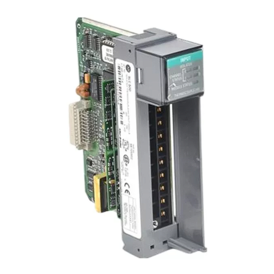
- Page 1 Thermocouple/mV Isolated Input Module Catalog Number 1746-INT4 User Manual...
- Page 2 Allen-Bradley, SLC 500, SLC, RSLogix 500, TechConnect, Rockwell Automation, ControlLogix, and RSLinx are trademarks of Rockwell Automation, Inc. Trademarks not belonging to Rockwell Automation are property of their respective companies.
-
Page 3: Table Of Contents
Table of Contents Preface Use This Manual ........7 Who Should Use This Manual . - Page 4 Replacement Parts....... . 70 Contacting Rockwell Automation ..... 70...
- Page 5 Table of Contents Appendix D Channel Calibration About the Procedure ......103 Appendix E CSA Hazardous Location Approval Glossary...
- Page 6 Table of Contents Publication 1746-UM614B-EN-P - September 2007...
-
Page 7: Preface
Preface Use This Manual Read this preface to familiarize yourself with the rest of the manual. This preface covers the following topics: • Who should use this manual • The purpose of this manual • Terms and abbreviations • Conventions used in this manual •... -
Page 8: Additional Resources
Preface Additional Resources The following documents contain information that may be helpful to you as you use Allen-Bradley SLC products. To obtain a copy of any of the Allen-Bradley documents listed, contact your local Allen-Bradley office or distributor. Resource Description SLC 500 Systems Selection Guide, publication 1747-SG001 An overview of the SLC 500 family of products SLC 500 Module Hardware Style User Manual, publication... -
Page 9: Compliance With European Union Directives
Chapter Module Overview This chapter describes the thermocouple/millivolt isolated input module and explains how the SLC controller reads thermocouple or millivolt analog input data from the module. The following information is included: • Compliance with European Union Directives • General description and hardware features •... -
Page 10: General Description
Module Overview General Description The module stores digitally-converted thermocouple and/or millivolt (mV) analog data in its image table for retrieval by all fixed and modular SLC 500 processors. The module supports connections from any combination of up to four thermocouple and/or mV analog sensors. - Page 11 Module Overview Hardware Features The module fits into any single slot for I/O modules in either an SLC 500 modular system or an SLC 500 fixed system expansion chassis (1746-A2). It is a Class 1 module (uses eight input words and eight output words).
-
Page 12: System Overview
Module Overview Diagnostic LED Indicator The module contains diagnostic LED indicator that help you identify the source of problems that may occur when cycling power or during normal operation. Power cycling and channel diagnostics are explained in Chapter 8, Module Diagnostics and Troubleshooting. System Overview The module communicates with the SLC 500 processor and receives +5V dc and +24V dc power from the system power supply through... - Page 13 Module Overview System Operation When you cycle power, the module checks its internal circuits, memory, and basic functions. During this time, the module status indicator remains off. If the module finds no faults, it turns on its module status indicator. System Operation Channel Data Word Channel Status Word...
- Page 14 Module Overview Module Addressing The module requires eight words each in the SLC processor’s input and output image tables. Addresses for the module in slot e are as follows: I:e.0…3 thermocouple/mV data for channels 0…3, respectively I:e.4…7 status data for channels 0…3, respectively O:e.0…3 configuration data for channels 0…3, respectively O:e.4…7 reserved for future use.
-
Page 15: Block Diagram Of Isolated-Channel Input Circuits
Module Overview Block Diagram of This illustration shows a block diagram for the analog input circuitry. Isolated-Channel Input Block Diagram Circuits Terminal Block Module Circuitry CJCA Sensor ± Open-circuit Channel 0 Digital Value Detection Analog to 8 Hz Channel 0 & Multiplexer Digital Digital... - Page 16 Module Overview Publication 1746-UM614B-EN-P - September 2007...
-
Page 17: Chapter 2 Required Tools
Chapter Quick Start Use this chapter as an abbreviated procedure for getting the module into operation or as an overview if you need the additional steps described in subsequent chapters. This chapter assumes that you understand the following things: • SLC 500 products •... -
Page 18: Procedures
Quick Start Procedures Follow these precautions to prevent damaging the module from IMPORTANT electrostatic discharge: • Before handling the module, rid yourself of electric charge by touching a grounded object. • Avoid touching connector terminations and circuit components. • Keep the module in its electrostatic shielded bag when not in use. 1. - Page 19 Quick Start 3. Install the module. Make sure system power is off; then insert the module into the I/O chassis. In this example procedure, the module is inserted into slot 1. Top and Bottom Module Releases Card Guide 4. Connect thermocouple wires to channel 0 on the module’s terminal block.
- Page 20 Quick Start 6. Set up Channel 0. Determine the operating parameters for channel 0. This example shows the channel 0 configuration word defined with all defaults (0) except for the channel enable (bit 11=1). Module assumed in slot 1. (For details on channel configuration, refer to the configuration worksheet on page 22).
- Page 21 Quick Start Data Table Display of Integer File N10:0 address data address data N10:0 0000 1000 0000 0000 Ladder Logic to Transfer N10:0 to the Module: When cycling power, the first pass bit (S:1/15) is set for one scan, enabling the First Pass Bit COPY instruction to transfer the COPY FILE...
-
Page 22: Channel Configuration Worksheet
Quick Start 10. Monitor the status of input channel 0 to determine its configuration setting and operational status. This is useful for troubleshooting when the blinking channel LED indicates that an error has been flagged. If the Module Status LED indicator is off, or if the Channel 0 LED indicator is off or blinking, refer to Chapter 8. - Page 23 Quick Start Channel Configuration Word (O:e.0 … O:e.3) — Bit Descriptions (Continued) Bit or Define To select Set these bits in the Channel Configuration Word Description Bits 15…12 11 10 9 8 7 6 5 4 3 2 1 0 4, 5 Data Engr.
- Page 24 Quick Start Publication 1746-UM614B-EN-P - September 2007...
-
Page 25: Electrostatic Damage
Chapter Install and Wire the Module This chapter tells you how to: • avoid electrostatic damage. • determine the module’s chassis power requirement. • install the module. • wire signal cables to the module’s terminal block. • install the ferrite collar. Electrostatic Damage Electrostatic discharge can damage semiconductor devices inside this module if you touch backplane connector pins. - Page 26 Install and Wire the Module Considerations for a Modular System Fixed Controller Compatibility Module INT4 5V dc 24V dc Place your module in any slot of an SLC 500 modular, or modular expansion chassis, except for the leftmost slot (slot 0) reserved for the 0.035 —...
-
Page 27: Module Installation And Removal
Install and Wire the Module (455, 0) Module 5V dc 24V dc 0.185 INT4 0.110 0.085 (85) Total 0.295 0.085 (295, 85) (295) 5V dc Current (255, 180) (mA) (0, 180) 24V dc Current (mA) Some analog I/O modules, such as the 1746-FIO4I, 1746-FIO4V, IMPORTANT 1746-NO4I, and 1746-NO4V, may require an additional 24V dc power supply. - Page 28 Install and Wire the Module Terminal Block Removal Never install, remove, or wire modules with power applied to ATTENTION the chassis or devices wired to the module. Follow these steps to remove the terminal block. 1. Loosen the two terminal-block release screws. To avoid cracking the terminal block, alternate between screws as you remove them.
- Page 29 Install and Wire the Module 3. Cover unused slots with the Card Slot Filler, catalog number 1746-N2. 4. To remove, press the releases at the top and bottom of the module, and slide the module out of the chassis slot. Card Guides Top and Bottom Releases...
-
Page 30: Wire The Module
Install and Wire the Module Wire the Module The module contains a green, 18-position, removable terminal block. Terminal Block (Terminal Block Spare Part Catalog Number 1746-RT32) Release Screw CJC A+ CJC Assembly Channel 0+ CJC A- Channel 0- Channel 1+ Do NOT use these Channel 1-... - Page 31 Install and Wire the Module Wiring Considerations Thermocouple inputs are highly susceptible to electrical noise due to the small signal amplitudes (microvolt/°C). Most applications require that the processor and I/O chassis be installed in an industrial enclosure to reduce the effects of electrical interference. Consider the following conditions when selecting a slot location for the module.
- Page 32 Install and Wire the Module Prepare and Wire the Cables Follow these steps to prepare and connect cable leads and drain wires. (Remove foil shield and drain wire from sensor-end of the cable.) Signal Wires Cable Drain Wire Signal Wires (At the module-end of the cable, extract the drain wire but remove the foil shield.) 1.
- Page 33 Install and Wire the Module 7. At the source-end of cables from mV devices: – remove the drain wire and foil shield. – apply shrink wrap as an option. – connect to mV devices keeping the leads short. If noise persists, try grounding the opposite end of the cable, IMPORTANT instead.
-
Page 34: Install The Ferrite Collar
Install and Wire the Module Install the Ferrite Collar For immunity to electrical noise with this CE-marked module, insert a ferrite collar (Fair-Rite Inc. part number 0443164151) around the input cables immediately beneath the module in the I/O chassis. Follow these steps to install the ferrite collar. 1. -
Page 35: Chapter 4 Module Id Code
Chapter Preliminary Operating Considerations This chapter explains how the module and the SLC processor communicate through the processor’s I/O image tables. It also describes the module’s input filter characteristics. Topics discussed include: • module ID code. • module addressing. • input channel characteristics. •... -
Page 36: Module Addressing
Preliminary Operating Considerations Module Addressing The following memory map shows you how the SLC processor’s output and input image tables are defined for the module. Memory Map Bit 15 Bit 0 Channel 0 Configuration Word Word 0 Channel 1 Configuration Word Word 1 Channel 2 Configuration Word Word 2... - Page 37 Preliminary Operating Considerations Chapter 6, Channel Configuration, Data, and Status, gives you detailed bit information about the data content of the configuration word. Input Image — Data Words and Status Words Eight words of the SLC processor’s input image table are reserved for the module.
-
Page 38: Input Channel Characteristics
Preliminary Operating Considerations Input Channel Each channel has an 8 Hz digital filter for input noise rejection, a multiplexer for processing cold junction compensation (CJC) values, Characteristics and an analog-to-digital (A/D) converter to provide digital values for SLC processing. Channel Cut-off Frequency, Update Time, and Step Response The channel cut-off frequency is defined as the point on the frequency response curve where frequency components of the input signal are passed with 3 dB of attenuation by the input filter. - Page 39 Preliminary Operating Considerations Cut-off Frequencies Frequency Response of the 8 Hz Filter Converter Step Response (worst case) for Filter, Multiplexer, and A/D Attenuation % of Final Value 00 db 100% -25db Multiplex CJC Values A/D Conversion -50db (200 ms) (200 ms) -75db -100db Frequency —...
-
Page 40: Response To Slot Disabling
Preliminary Operating Considerations Response to Slot Disabling By writing to the status file in your modular SLC processor you can disable any chassis slot. Refer to your SLC programming manual for the slot disable/enable procedure. Always understand the implications of disabling the module ATTENTION before using the slot disable feature. -
Page 41: Click And Drag Configuration
Chapter Access Files to Configure I/O There are two ways to configure the SLC chassis for a 1746-INT4 module. You can either click and drag items from the list or you can use the Read IO Config method. Click and Drag Follow these steps to configure the SLC chassis by clicking and dragging modules. -
Page 42: Read Io Config Method
Access Files to Configure I/O The I/O Configuration is now complete. Each slot shows the corresponding module that is located on the rack. In this example, 1746-INT4 is in slot 1. Read IO Config Method Follow these steps to configure the SLC chassis by using the read I/O configuration method. - Page 43 Access Files to Configure I/O 2. Place the 1746-INT4 module into the correct slot by clicking Read IO Config. The following screen appears. 3. Select either the driver and processor node number or click Who Active to browse for the device. •...
- Page 44 Access Files to Configure I/O The Who Active screen lets you to browse for the SLC device. 4. Locate the SLC chassis under the appropriate driver and click You return to the Read IO Config dialog. 5. Click Read IO Config and the rack is populated automatically. The I/O Configuration is now complete.
-
Page 45: Channel Configuration
Chapter Channel Configuration, Data, and Status This chapter examines channel configuration and status words, and explains how you use them. It gives you information about how to: • configure a channel. • check a channel’s status. Channel Configuration Channel configuration words appear in the SLC controller’s output image table as shown below. - Page 46 Channel Configuration, Data, and Status The configuration word default settings are all zero. Next, we describe how you set configuration bits of a channel configuration word to set up the following channel parameters: • Type of thermocouple or mV input •...
- Page 47 Channel Configuration, Data, and Status Channel Configuration Word (O:e.0 through O:e.3) — Bit Descriptions Bit or Define To Select Set these bits in the Channel Configuration Word Description Bits 15…12 11 10 9 8 7 6 5 4 3 2 1 0 0…3 Input TC Type J...
- Page 48 Channel Configuration, Data, and Status Channel Configuration Word (O:e.0 through O:e.3) — Bit Descriptions (Continued) Bit or Define To Select Set these bits in the Channel Configuration Word Description Bits 15…12 11 10 9 8 7 6 5 4 3 2 1 0 9, 10 Unused Unused These bits must be zero for a...
- Page 49 Channel Configuration, Data, and Status Select the Correct Data Format To provide the highest display resolution, select Scaled-for-PID or Proportional Counts. To use either one, you may have to convert channel data to/from Engineering Units, manually or logically. The following examples show you how to do this. Use Scaled-for-PID and Proportional Counts You must obtain the minimum (S ) and maximum (S...
-
Page 50: Channel Configuration Procedure
Channel Configuration, Data, and Status Channel Configuration Use this procedure once for each channel to set configuration bits that determine channel operation. Copy it as needed to write down Procedure configuration selections of all your channels. Use the table of bit descriptions and the blank configuration worksheet in Appendix B. -
Page 51: Use Channel Data Words
Channel Configuration, Data, and Status Use Channel Data Words Thermocouple or millivolt input data reside in I:e.0 to I:e.3 of the SLC controller’s input image file (where e is the slot number assigned to the module). The values depend on the input type and data format that you select. - Page 52 Channel Configuration, Data, and Status Resolution of a Channel Data Word Input Data Format Type Engineering Units x 10 Engineering Units x 1 Scaled-for-PID Proportional Counts ° Celsius ° Fahrenheit ° Celsius ° Fahrenheit ° Celsius ° Fahrenheit ° Celsius °...
-
Page 53: Use Channel Status Words
Channel Configuration, Data, and Status Use Channel Status Words Channel status words are stored in the SLC controller’s input image file at addresses I:e.4 to I:e.7 (where e is the slot number assigned to the module). Status words 4…7 correspond to and reflect the configuration of channels 0…3 (O:e.0…O:e.3). - Page 54 Channel Configuration, Data, and Status Channel Status Word, Channels 0…3 (I:e.4 through I:e:.7) — Bit Definitions Bit or Reflect/ Configured for With This Bit Code Reflects Configuration in Bits Indicate Bits 0…11 and Indicates 15 14 13 12 11 10 9 8 7 6 5 4 3 2 1 0 Detected Faults in Bits 12…15 0 …...
- Page 55 Channel Configuration, Data, and Status Channel Status Word, Channels 0…3 (I:e.4 through I:e:.7) — Bit Definitions (Continued) Bit or Reflect/ Configured for With This Bit Code Reflects Configuration in Bits Indicate Bits 0…11 and Indicates 15 14 13 12 11 10 9 8 7 6 5 4 3 2 1 0 Detected Faults in Bits 12…15 Open...
- Page 56 Channel Configuration, Data, and Status Out-of-range Detection (Bit 13 for under-range, bit 14 for over-range) The module tests all enabled channels for an out-of-range condition each time it scans its inputs. Possible causes of an out-of-range condition include: • the temperature is too hot or too cold for the thermocouple being used.
-
Page 57: Chapter 7 Processor Basics
Chapter Ladder Programming Examples Earlier chapters explained how configuration words define channel operation. This chapter shows examples of ladder logic that you write • load configurations into the output image file to be scanned to the module. • change the configuration of a channel. •... -
Page 58: Load Channel Configurations For Transfer To The Module
Ladder Programming Examples During the I/O scan, the SLC processor scans configuration words from its output image file to the module, and scans data and status words from the module to its input image file. The SLC processor scans its I/O following each program scan. We repeat the configuration word because it is used often in the examples. -
Page 59: Change A Channel Configuration
Ladder Programming Examples 2. Program a rung of ladder logic to copy the integer file #N10 into output image file O:3.0 through O:3.3. First Pass Bit Initialize NT4 COPY FILE Source #N10:0 Dest #O:3.0 Length When cycling power, bit S:1/15 is set for the first program scan. It enables the Copy instruction to load configurations into the output image file for transfer to the module in the Change a Channel The following example explains how to change the channel... - Page 60 Ladder Programming Examples Program Rung 2:0 Set up all four channels COPY FILE Source #N10:0 Dest #O:3.0 Length Rung 2:1 Set channel 2 to CJC I:1.0 MOVE [OSR] Source N10:4 Dest O:3.2 Rung 2:2 Set channel 2 back to Type K I:1.0 MOVE [OSR]...
-
Page 61: Verify Changes To A Channel Configuration
Ladder Programming Examples Verify Changes to a When changing a channel configuration, there is always a delay until the ladder logic reads the new data word based on the new Channel Configuration configuration. Therefore, it is important to verify that the module successfully stored the new channel configuration word. -
Page 62: Process A Channel Input With The Pid Instruction
Ladder Programming Examples Process a Channel Input The module was designed to input a channel directly to a PID instruction of an SLC 5/02 processor or later without the need of an with the PID Instruction intermediate scale operation. Use channel data as the process variable for the PID EXAMPLE instruction. -
Page 63: Monitor Channel Status Bits
Ladder Programming Examples Monitor Channel Status This example shows how you could monitor the open-circuit error bit of each channel and set an alarm bit if the module detects an open Bits input. An open-circuit error can occur if a thermocouple or CJC thermistor wire breaks or becomes disconnected from the terminal block. - Page 64 Ladder Programming Examples Program Rung 2:0 First Pass Bit Initialize NT4 COPY FILE Source #N10:0 Dest #O:3.0 Length Rung 2:1 Channel 0 Channel 0 Channel 0 Status Open Alarm O:2.0 I:3.4 I:3.4 Rung 2:2 Channel 1 Channel 1 Channel 1 Status Open Alarm...
-
Page 65: Module And Channel Diagnostics
Topics include: • module and channel diagnostics. • status indicators. • troubleshooting flowchart. • replacement parts. • contacting Rockwell Automation. Module and Channel The module operates at two levels. Diagnostics • Module level • Channel level Module level operation includes functions such as cycling power, configuration, and communication with the SLC processor. -
Page 66: Led Indicators
Module Diagnostics and Troubleshooting Channel Diagnostics When a channel is enabled, the module checks for a valid configuration. Then on each scan of its inputs, the module checks for out-of-range and open-circuit fault conditions of its inputs including the CJC thermistor. When the module detects a failure of any channel diagnostic test, it causes the channel status LED indicator to blink and sets the corresponding channel fault bit (bits 12…15 of the channel status... - Page 67 Module Diagnostics and Troubleshooting Module-status and Channel-status LED Indicators If Module Status And Channel Then Take This Corrective Action LED Indicator is Status LED Indicator is The channel is enabled. No action required. Blinking The module detected: Examine error bits in the status word: open-circuit condition if bit 12 = 1, the input has an open-circuit;...
- Page 68 Module Diagnostics and Troubleshooting Out-of-range Detection (Bit 13 for under-range, bit 14 for over-range) The module tests all enabled channels for an out-of-range condition each time it scans its inputs. Possible causes of an out-of-range condition include the following: • The temperature is too hot or too cold for the thermocouple being used.
- Page 69 Module Diagnostics and Troubleshooting Troubleshooting Flowchart Check LED indicators on module. Module Status Module Status Channel Status LED Channel Status Channel Status LED indicator off. LED indicator on. indicator(s) blinking. LED indicator off. LED indicator on. Channel is not Channel enabled Normal module Module fault enabled.
-
Page 70: Replacement Parts
1746-R13 Series B 1746-INT4 User Manual 1746-UM614 Contacting Rockwell If you need to contact Rockwell Automation for assistance, please have the following information available when you call: Automation • A clear statement of the problem including a description of what... -
Page 71: Basic Example (To Display A Temperature)
Chapter Application Programming Examples This chapter provides two application examples to help you use the module. • Basic example • Supplementary example The basic example lets you display a temperature. The supplementary example lets you manually select the display of temperature in °C or °F. - Page 72 Application Programming Examples Configuration Word Type Not Used Channel Not Used Temp Response to Data Enable Units Open-circuit Format of Input 0 0 0 0 = Type J 0 1 1 0 = Type B 0 = Disable 0 = °C 0 0 = zero 0 0 = EU x1 1 = Enable...
-
Page 73: Supplementary Example (Select Display In °C Or °F)
Application Programming Examples Supplementary Example This example shows how to display the temperature of several thermocouples at display panel. A selector switch (I:2/0) lets the (select display in °C or °F) operator choose between displaying temperatures in °C or °F. A second selector switch (I:2/1) lets the operator switch a display between the ambient temperature near the bath and the temperature inside the control cabinet containing the SLC controller. - Page 74 Application Programming Examples Channel Configuration All channels are configured for: • display temperature to tenths of a degree. • zero data word in the event of an open-circuit. Configuration setup for ambient thermocouple: • channel 0. • type T thermocouple. Configuration setup for bath thermocouple: •...
- Page 75 Application Programming Examples Program Setup Follow these steps to set up the program. 1. Set up two configuration words for each channel in file N10, one for °C and the other for °F. Include two configuration words for the CJC temperature in the cabinet containing the SLC controller.
- Page 76 Application Programming Examples Program The first six rungs change channel configurations based on the position of the two selector switches. Rung 2.0 If the degrees selector switch is switched to Fahrenheit, configure all four channels to read in degrees Fahrenheit. The default for channel 0 is to read the ambient temperature thermocouple. Degrees Selector Switch = Configure Channels...
- Page 77 Application Programming Examples Rung 2.4 If the ambient/cabinet selector switch is switched to ambient, and the degrees selector switch is switched to Celsius, configure channel 0 to read the ambient temperature thermocouple in degrees Celsius. Degrees Selector Ambient/Cabinet Switch = Selector Switch = Configure Channels Fahrenheit...
- Page 78 Application Programming Examples Rung 2.8 Convert data words to BCD format and send them to the LED indicator displays. Write Ambient or Cabinet Temperature to the Display TO BCD Source I:1.0 Dest O:3.0 Rung 2.9 Write Bath Temperature to the Display TO BCD Source I:1.1...
-
Page 79: Electrical Specifications
Appendix Module Specifications This appendix lists the specifications for the 1746-INT4 Thermocouple/mV Isolated Input Module. Electrical Specifications Attribute Value Backplane current consumption 110 mA @ 5V dc 85 mA @ 24V dc Backplane power consumption 0.6 W max (0.55 W @ 5V dc, 2 W @ 24V dc Number of channels 4 (backplane and channel-to-channel isolated) I/O chassis location... -
Page 80: Environmental Specifications
Module Specifications Attribute Value Max wire size Two 1.6 mm (14 AWG) wires per terminal 150 Ω max loop impedance, for < 1LSB error Max cable impedance Terminal strip Removable, catalog number 1746-RT32 (1) Refer to the thermocouple manufacturer for the correct extension wire. Environmental Specifications Attribute... - Page 81 Module Specifications Attribute Value Temperature scale °C or °F and 0.1 °C or 0.1 °F (selectable) Millivolt scale, dc 0.1 mV or 0.01 mV (selectable) Open-circuit detection 20 nA typical leakage current Open-circuit detection Upscale, downscale, or zero (selectable) Time to detect open-circuit 5 s, typical Input step response 0…99.9% in 600 ms (worst case)
- Page 82 Module Specifications Input Type Max Error Max Error Temperature Drift @ 25 °C @ 77 °F (0… 60 °C) ±1.79 °C ±3.23 °F ±0.080 °C/°C, °F/°F ±2.28 °C ±4.11 °F ±0.270 °C/°C, °F/°F ±2.52 °C ±4.54 °F ±0.280 °C/°C, °F/°F ±50 mV ±50 µV ±50 µV...
- Page 83 Module Specifications Thermocouple Resolution Type C Thermocouple 0.32 C @ 2000 0.26 C @ 0 Resolution 0.20 C @ 1000 (˚C) 1000 1250 1500 1750 2000 2250 Temperature (˚C) Type D Thermocouple 0.34 C @ 0 0.27 C @ 2000 Resolution 0.20 C @ 1100...
- Page 84 Module Specifications Type J Thermocouple 0.18 C @ -200 Resolution (˚C) 0.06 C @ 275 0.05 C @ 750 -300 -150 Temperature (˚C) Type K Thermocouple C @ -250 Resolution (˚C) 0.08 C @ 550 0.10 C @ 1350 -300 -150 1050 1200...
- Page 85 Module Specifications Type E Thermocouple 1.70 C @ -250 Resolution (˚C) 0.05 C @ 1000 0.04 C @ 365 -300 -150 1050 1200 Temperature (˚C) Type R Thermocouple 0.75 0.68 C @ 0 0.60 Resolution (˚C) 0.45 0.26 C @ 885 0.28 C @ 1750 0.30...
- Page 86 Module Specifications Type S Thermocouple 0.75 0.68 C @ 0 0.60 0.45 Resolution (˚C) 0.31 C @ 1750 0.31 C @ 885 0.30 0.15 -300 -150 1050 1200 1350 1500 1650 1800 Temperature (˚C) Type T Thermocouple C @ -250 Resolution (˚C) 0.08...
- Page 87 Module Specifications Type B Thermocouple 1.20 1.13 C @ 300 0.90 Resolution (˚C) 0.60 0.38 C @ 1060 0.31 C @ 1800 0.30 -300 -150 900 1050 1200 1350 1500 1650 1800 1950 Temperature (˚C) Type N Thermocouple 0.170 0.150 0.13 C @ 0 0.125...
- Page 88 Module Specifications Publication 1746-UM614B-EN-P - September 2007...
- Page 89 Appendix Channel Configuration Worksheets Select your bit configurations. Write them down at the bottom of the worksheet. Use one worksheet for each channel. Channel Configuration Word (O:e.0 through O:e.3) — Bit Descriptions Bit or Define To Select Set these bits in the Channel Configuration Word Description Bits 15…12 11 10 9 8 7 6 5 4 3 2 1 0...
- Page 90 Channel Configuration Worksheets Channel Configuration Word (O:e.0 through O:e.3) — Bit Descriptions (Continued) Bit or Define To Select Set these bits in the Channel Configuration Word Description Bits 15…12 11 10 9 8 7 6 5 4 3 2 1 0 6, 7 Open- Zero...
- Page 91 Channel Configuration Worksheets Select your bit configurations. Write them down at the bottom of the worksheet. Use one worksheet for each channel. Channel Configuration Word (O:e.0 through O:e.3) — Bit Descriptions Bit or Define To Select Set these bits in the Channel Configuration Word Description Bits 15…12 11 10 9 8 7 6 5 4 3 2 1 0...
- Page 92 Channel Configuration Worksheets Channel Configuration Word (O:e.0 through O:e.3) — Bit Descriptions (Continued) Bit or Define To Select Set these bits in the Channel Configuration Word Description Bits 15…12 11 10 9 8 7 6 5 4 3 2 1 0 Units Degrees C Select °C/°F for thermal inputs.
- Page 93 Channel Configuration Worksheets Select your bit configurations. Write them down at the bottom of the worksheet. Use one worksheet for each channel. Channel Configuration Word (O:e.0 through O:e.3) — Bit Descriptions Bit or Define To Select Set these bits in the Channel Configuration Word Description Bits 15…12 11 10 9 8 7 6 5 4 3 2 1 0...
- Page 94 Channel Configuration Worksheets Channel Configuration Word (O:e.0 through O:e.3) — Bit Descriptions (Continued) Bit or Define To Select Set these bits in the Channel Configuration Word Description Bits 15…12 11 10 9 8 7 6 5 4 3 2 1 0 Units Degrees C Select °C/°F for thermal inputs.
- Page 95 Channel Configuration Worksheets Select your bit configurations. Write them down at the bottom of the worksheet. Use one worksheet for each channel. Channel Configuration Word (O:e.0 through O:e.3) — Bit Descriptions Bit or Define To Select Set these bits in the Channel Configuration Word Description Bits 15…12 11 10 9 8 7 6 5 4 3 2 1 0...
- Page 96 Channel Configuration Worksheets Channel Configuration Word (O:e.0 through O:e.3) — Bit Descriptions (Continued) Bit or Define To Select Set these bits in the Channel Configuration Word Description Bits 15…12 11 10 9 8 7 6 5 4 3 2 1 0 Units Degrees C Select °C/°F for thermal inputs.
-
Page 97: J Type Thermocouple (Iron Versus Copper-Nickel
Appendix Thermocouple Descriptions The descriptions of thermocouples J, K, T, E, R, and S were extracted from NBS Monograph 125 (IPTS–68) issued March 1974. We also describe types C and D. J Type Thermocouple The J thermocouple is the least suitable for accurate thermometry because there are significant nonlinear deviations in the (iron versus copper-nickel thermoelectric output from different manufacturers.) -
Page 98: K Type Thermocouple (Nickel-Chromium Versus Nickel-Aluminum)
Thermocouple Descriptions ASTM Standard E230-72 in the Annual Book of ASTM Standards [1972] specifies that the standard limits of error for Type J commercial thermocouples be ±2.2 °C (±35.9 °F) between 0…277 °C (32…531 °F) and ±3/4% between 277…760 °C (531…1400 °F). Limits of error are not specified for Type J thermocouples below 0 °C (32 °F) or above 760 °C (1400 °F). -
Page 99: T Type Thermocouple (Copper Versus Copper-Nickel
Thermocouple Descriptions ASTM Standard E230-72 in the Annual Book of ASTM Standards [1972] specifies that the standard limits of error for Type K commercial thermocouples be ±2.2 °C (±35.9 °F) between 0…277 °C (32…530.6 °F) and ±3/4% between 277…1260 °C (530.6…2300 °F)/ Limits of error are not specified for the Type K thermocouples below 0 °C (32 °F).) -
Page 100: E Type Thermocouple (Nickel-Chromium Versus Copper-Nickel
Thermocouple Descriptions Type T thermoelements are not well suited for use in nuclear environments, since both thermoelements are subject to significant changes in composition under thermal neutron irradiation. The copper in the thermoelement is converted to nickel and zinc. Because of the high thermal conductivity of Type TP thermoelements, special care should be exercised in the use of the thermocouples to insure that both the measuring and reference junctions assume the desired temperatures.) -
Page 101: S And R Type Thermocouple S
Thermocouple Descriptions ASTM Standard E230-72 in the Annual Book of ASTM Standards [1972] specifies that the standard limits of error for the Type E commercial thermocouples be ±1.7 °C (±35 °F) between 0…316 °C (32…600 °F) and ±1/2% between 316…871 °C (600…1600 °F). Limits of error are not specified for Type E thermocouples below 0 °C (32 °F). -
Page 102: C And D Type Thermocouples
Thermocouple Descriptions C and D Type Types C and D thermocouples are recommended for use in the temperature range from 0 2320 °C (32…4208 °F) in non-oxidizing … Thermocouples inert atmospheres. They are not practical for use below 399 °C C (tungsten-5% rhenium versus (750 °F). - Page 103 Appendix Channel Calibration This appendix shows you how to calibrate the module’s input channels. About the Procedure The purpose of the procedure is to store a pair of calibration values in EEPROM for each channel to set channel accuracy at 0.05% of full range regardless of channel circuit tolerances.
- Page 104 Channel Calibration Calibration Codes and Status Use the following format for entering calibration code words and reading calibration status bits. You enter calibration values in Hex. You can read channel status OK bits at different steps in the calibration procedure, one bit for each channel you are calibrating. Use Word 5 (Output Image —...
- Page 105 Channel Calibration Calibration Procedure To perform this calibration procedure, you need a precision dc voltmeter and precision power supply that displays and maintains a calibration voltage to 1/1000 of a millivolt: at 0.000 mV and 90.000 mV. Prepare for calibration by removing the thermocouple leads from the input terminals of the channels that you want to calibrate.
- Page 106 Channel Calibration 8. Observe bits 4…7 in status word 4. If all the channels you are calibrating see 90.000 mV, the module returns status-OK bits set, one bit for each channel (F Hex for all four channels). Otherwise, the module returns channel status bits set to zero.
- Page 107 Appendix CSA Hazardous Location Approval CSA Hazardous Location Approval Approbation d’utilisation dans des emplacements dangereux par la CSA CSA certifies products for general use as well as for use in La CSA certifie les produits d’utilisation générale aussi bien que hazardous locations.
- Page 108 CSA Hazardous Location Approval CSA Hazardous Location Approval Approbation d’utilisation dans des emplacements dangereux par la CSA The following warnings apply to products having CSA certification Les avertissements suivants s’appliquent aux produits ayant la for use in hazardous locations. certification CSA pour leur utilisation dans des emplacements dangereux.
- Page 109 Glossary Terms and Abbreviations The following terms and abbreviations are used throughout this manual. For definitions of terms not listed here refer to the Industrial Automation Glossary, Allen-Bradley publication AG-7.1. Refers to the analog-to-digital converter within the module. The converter produces a digital value whose magnitude is proportional to the instantaneous magnitude of an analog input signal.
- Page 110 Glossary configuration word Contains the channel configuration information needed by the module to configure and operate each channel. The module is designed for software rather than hardware configuration. cut-off frequency The frequency at which the input signal is attenuated 3 dB by the digital input filter.
- Page 111 Glossary input data scaling Depends on the data format that you select for the channel data word. You can select from scaled-for-PID or Engineering Units for millivolt, thermocouple, or CJC inputs, which are automatically scaled. You may also select proportional counts, which you must compute to fit your application’s temperature or voltage resolution.
- Page 112 Glossary status word Contains status information about the channel’s current configuration and operational state. You can use this information in your ladder program to determine whether the channel data word is valid. step response time This is the time required for the module to process an input signal to reach 99.9% of its expected final value, given a large step change in the input signal.
- Page 113 Index accessing files for IO cofiguration 41 input channel characteristics 38 channel cut off frequency 38 resolution of channel and input device 39 step response 38 block diagram 15 update time 38 input ranges 10 installation and wiring 25 IO configuration 41 cables preparing and wiring 32 isolated channel input circuits block channel...
- Page 114 Index selecting correct data format 49 terminal block removal 28 slot disabling 40 input response 40 output response 40 update time 38 status words 37 using channel data words 51 step response 38 using channel status words 53 system overview 12 compatibility with cables 14 compatibility with millivolt devices 14 compatibility with thermocouple 14...
- Page 116 Outside United Please contact your local Rockwell Automation representative for States return procedure. Publication 1746-UM614B-EN-P - September 2007 PN XXXXXX-XX Supersedes Publication 1746-6.16 - January 1999 Copyright © 2007 Rockwell Automation, Inc. All rights reserved. Printed in the U.S.A.
Need help?
Do you have a question about the AB quality Allen-Bradley 1746-INT4 and is the answer not in the manual?
Questions and answers