Table of Contents
Advertisement
Quick Links
Advertisement
Table of Contents

Related Manuals for Rockwell Automation Allen-Bradley 1746-BTM


Summary of Contents for Rockwell Automation Allen-Bradley 1746-BTM
- Page 1 Barrel Temperature Control Module 1746-BTM User Manual...
- Page 2 Reproduction of the contents of this copyrighted publication, in whole or part, without written permission of Rockwell Automation, is prohibited. Throughout this manual we use notes to make you aware of safety...
- Page 3 European Communities (EC) If this product has the CE mark it is approved for installation within the European Union and EEA regions. It has been designed and Directive Compliance tested to meet the following directives. EMC Directive This product is tested to meet the Council Directive 89/336/EC Electromagnetic Compatibility (EMC) by applying the following standards, in whole or in part, documented in a technical construction file:...
- Page 4 Summary of Changes This manual has been revised extensively. Major changes include: • Ladder code addresses have been changed. • The sample ladder code has been extensively changed. As a result, Chapter 9 has been extensively changed. • Examples outlining the mathematical relationships involved in Startup Aggressiveness Factor and Ramp Rates have been included in Chapter 3 •...
- Page 5 Summary of Changes Publication 1746-6.10 - September 1999...
- Page 6 Preface Using This Manual This manual shows you how to use the Barrel Temperature Control Module (cat. no. 1746-BTM) in an Allen-Bradley SLC system for barrel temperature control and other injection molding or extrusion related temperature control applications. The manual explains how to install, program, calibrate, and troubleshoot the BTM module.
- Page 7 Preface SLC Processor The 1746-BTM module is compatible with any SLC processor that supports M0/M1 files, such as the SLC 5/05, SLC 5/04, SLC 5/03, and SLC 5/02 controllers. Vocabulary In this manual, we refer to: • the barrel temperature control module at the “1746-BTM module,”...
-
Page 8: Table Of Contents
Table of Contents Chapter 1 Getting Started Temperature Control Using a BTM Module in an SLC System 1-1 Features of the Temperature Control Module ... 1-2 Module Outputs ....... . 1-2 Current CV . - Page 9 Table of Contents High/Low CV Limits ......3-5 Words 2 and 3 for Channel 1 ....3-5 TC Break Control .
- Page 10 Table of Contents Using the Output Image Table..... . 5-8 Operating Commands to Loops 1-4....5-8 Global Commands to All Loops .
- Page 11 Table of Contents Publication 1746-6.10 - September 1999...
-
Page 12: Getting Started
Chapter Getting Started This chapter gives you information on: • the function of the temperature control module • features of the temperature control module • time–proportioned output (TPO) • module addressing • response to slot disabling Use the 1746–BTM module only for barrel ATTENTION temperature control for injection molding applications or extruders in a local I/O chassis. -
Page 13: Features Of The Temperature Control Module
Getting Started Features of the Temperature The 1746–BTM module provides: Control Module • 4 independent temperature control loops • autotune PID loops (one loop or any combination of loops can be autotuned while other loops are running) • a unique start–up algorithm to minimize overshoot •... - Page 14 Getting Started Figure 1.2 TPO timing diagram CV% = (40%) X = on time (2.0 sec) Y = TPO period (5.00 sec) data in parenthesis refers to TPO bit sample program values. The TPO duty cycle (Y) must be considerable shorter in time than the system dead time.
-
Page 15: Module Addressing
Getting Started Module Addressing When you enter the module ID in processor configuration (off-line), the processor automatically reserves the required number of I/O image table words. In the figure below, that section of the I/O image table is designated by “slot e”. Its location in the I/O image table is determined by the module’s slot location “e”... -
Page 16: Output Response
Getting Started Output response When the slot for this module is disabled, configuration words in the SLC processor’s output image table are held in their last state and not transferred to the module. When the slot is re–enabled, output image table words are transferred to the module during the subsequent scan. - Page 17 Getting Started Publication 1746-6.10 - September 1999...
-
Page 18: Installing And Wiring
Chapter Installing and Wiring This document gives you information about: • avoiding electrostatic damage • compliance with European Union directive • determining the module’s chassis power requirement • planning for sufficient enclosure depth • choosing a module slot in a local I/O chassis •... -
Page 19: European Communities (Ec) Directive Compliance
Installing and Wiring European Communities (EC) If this product has the CE mark it is approved for installation within the European Union and EEA regions. It has been designed and tested Directive Compliance to meet the following directives. EMC Directive This product is tested to meet the Council Directive 89/336/EC Electromagnetic Compatibility (EMC) by applying the following standards, in whole or in part, documented in a technical construction... -
Page 20: Determining Power Requirements
Installing and Wiring Determining Power Requirements Table 2.A 5V dc amps 24V dc amps 0.110 0.085 When computing power supply requirements, add the values shown in Table 2.A to the requirements of all other modules in the SLC chassis to prevent overloading the chassis power supply. Choosing a Module Slot in Place your module in any slot of an SLC500 modular, or modular expansion chassis, except for the left–most slot (slot 0) reserved for... -
Page 21: Installing The Module
Installing and Wiring Installing the Module Follow this procedure: Never install, remove, or wire modules with power ATTENTION applied to the chassis or devices wired to the module. 1. Align the circuit board of the thermocouple module with the card guides located at the top and bottom of the chassis. 2. -
Page 22: Removing The Terminal Block
Installing and Wiring Removing the terminal block When installing the module, it is not necessary to remove the terminal block. But if you need to remove it, follow this procedure: 1. Alternately loosen the two retaining screws to avoid cracking the terminal block. -
Page 23: Wiring The Module
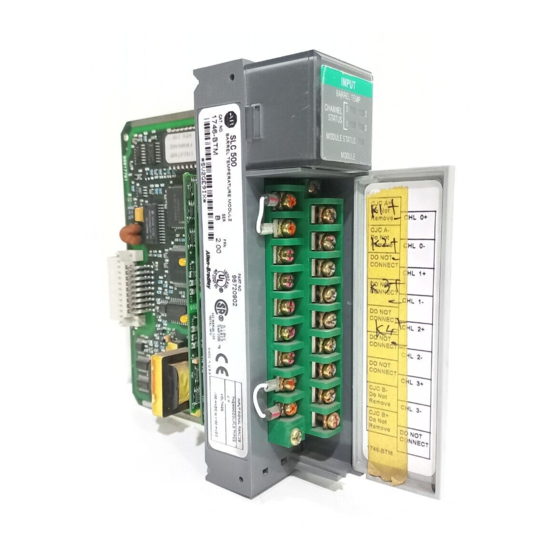
Installing and Wiring Wiring the Module The module has an 18–position, removable terminal block. The terminal block pin–out is shown below. Disconnect power to the SLC before attempting to ATTENTION install, remove, or wire the removable terminal wiring block. Figure 2.1 Terminal block pin out. Retaining Screw CJC A+ Channel 0+... -
Page 24: Wiring Considerations
Installing and Wiring Figure 2.2 Thermistor placement on the bottom of the terminal block Always attach red lug to the CJC+ terminal Wiring considerations Follow the guidelines below when planning your system wiring. • To limit the pickup of electrical noise, keep thermocouple and millivolt signal wires away from power and load lines. -
Page 25: Preparing And Wiring The Cables
Installing and Wiring Preparing and Wiring the Cables To prepare and connect cable leads and drain wires, follow these steps: Figure 2.3 Cable lead and drain wire preparation Remove the foil shield and drain wire from sensor-end of the cable Signal Drain Wire Signal... - Page 26 Installing and Wiring 7. At the source-end of cables from mV devices (See Figure 2.3 and Figure 2.4): – remove the drain wire and foil shield – apply shrink wrap as an option – connect to mV devices keeping the leads short Figure 2.4 Cable Preparation to Minimize Electrical Noise Interference Make unshielded wires Terminal...
- Page 27 2-10 Installing and Wiring Notes: Publication 1746-6.10 - September 1999...
-
Page 28: Configuring The Module
Chapter Configuring the Module You configure the module by setting words and bits for each loop in Configuration Block, N10:0–100, which your ladder logic uses to load the module’s M1 file. We cover bit selections and word descriptions. Refer to the table at the end of this chapter for selections, units, and defaults. -
Page 29: Enable Loop Alarms
Configuring the Module Enable Loop Alarms Word 1, Bit 6 for Channel 1 Set this bit to enable alarms for the designated loop. TC Break Response Word 1, Bits 7 and 8 for Channel 1 If the module detects a TC open wire for a loop in automatic mode, the module responds in one of these ways that you select: TC Break Response disables the loop... -
Page 30: Barrel/Non-Barrel Control
Configuring the Module Barrel/Non-barrel Control Word 1, Bit 12 for Channel 1 You select between barrel and non–barrel control. Select: for these applications: barrel control heat–only or heat/cool non–barrel control heat–only, cool–only, or heat/cool Barrel Control Select barrel control for multiple–zone applications in which there is thermal conduction between the zones. -
Page 31: Inner/Outer Zone Selection
Configuring the Module If you switch a loop between non– barrel and barrel ATTENTION control, you must re–autotune the loop before operating it. If you don’t re–autotune, the autotune values will be wrong for the application and the gains will be greatly distorted. Inner/Outer Zone Selection Word 1, Bit 13 for Channel 1 If you make a selection for barrel control, you also must select... -
Page 32: High/Low Cv Limits
Configuring the Module High/Low CV Limits Words 2 and 3 for Channel 1 Use CV High and Low Limits to set up the loop mode: For this loop mode: Low: High: heat, only 100% cool, only -100% heat/cool -100% +100% TC Break Control Word 4 or O:e.8 for Channel1 If a loop input circuit becomes open (open wire) the loop can not... -
Page 33: Heat/Cool Tpo Period
Configuring the Module in. If the contactor is energized for less than this value, the contactor will not close, but the attempt will count as a cycle. For example, suppose you set the TPO period for 10 seconds and the minimum ON time to 1 second. -
Page 34: Alarm Dead Band
Configuring the Module Alarm Dead Band Word 15 for Channel 1 Once the temperature alarm bits are on, they are kept on until the temperature drops below the high alarm by the alarm dead–band value or rise above the low alarm by this value. The alarm dead band applies to the CV value at the high and low temperature alarms and deviation alarm values. -
Page 35: Ramp Rates
Configuring the Module The values you enter in words 16 and 17 for loop 1 establish a minimum rate of change (°/min) in the temperature input (PV) that you allow when the the output (CV) is at 100% in automatic mode. The temperature change value you enter in word 16 divided by the period value you enter in word 17 is the thermal integrity rate. -
Page 36: Implied Decimal Point
Configuring the Module Implied Decimal Point When entering or reading integer values, the range, given in the associated table, tells you the implied decimal point. It is the number of digits to the right of the decimal point (for an example range of 0.0 thru 3276.7, the implied decimal point is 1). -
Page 37: Startup Aggressiveness Factor
3-10 Configuring the Module Configuration Block, M1 Configuration block (M1 file) contains 101 words as listed below. File, Loops 1-4 N10:0-100 Word numbers for loops 1–4 are in left–most IMPORTANT columns. For corresponding N7:xx address, add 10 to word the number. Startup Aggressiveness The startup aggresiveness factor (SAF) modifies the pre-set point value. -
Page 38: Ramp Rates
Configuring the Module 3-11 The higher the startup aggressiveness factor is, the IMPORTANT closer to setpoint you will go before you switch from the cold startup algorithms to PID control. If your pre-set point is to close to the actual setpoint you can expect overshoot to occur. - Page 39 3-12 Configuring the Module Table 3.A Block Header (word 0 / N10:0) = 8801 (-30719 decimal) Loops 1-4 Set a bit or enter a value Word # to Configure Bit Select or Range Monitor;no PID Control operation mode Control loop with PID Disable loop Type J input type...
-
Page 40: Setting Autotune And Gains Values
Chapter Setting Autotune and Gains Values This chapter shows you how to independently set the gains for each PID loop of the BTM module. This includes: • setting PID gains • autotuning the loops • fine tuning the loops • using the PID equation •... -
Page 41: Autotuning The Loops
Setting Autotune and Gains Values Once autotuning is complete, you must read the gains block from the module to store it in SLC processor memory. You can write the autotune and gains block either of these ways: • Send autotune block to the module in words 1-24 (NXX:110-134). -
Page 42: Fine-Tuning The Loops
Setting Autotune and Gains Values Whenever you write autotune values to the module, it re–calculates PID gains based on measured system parameters stored in the autotune block and your selection of low, medium, or high PID gain level stored in the latest configuration block. If you had changed the level of PID gains selection in the configuration block in the mean time, the PID gains calculated would be different from those calculated originally. -
Page 43: Using The Pid Equation
Setting Autotune and Gains Values If the loop is slow in reaching the set point either at start–up or at a change of set point, (See Figure 4.2) you may be able to improve the loop response by doing one or more of the following (in order of effectiveness): 1. -
Page 44: Entering Autotune/Gains Values With Implied Decimal Point
Setting Autotune and Gains Values Entering Autotune/Gains The autotune/gains block (M0 file) contains 49 words as listed below. For each gain value, you enter a 16–bit integer value. Values with Implied Decimal Point Because loop values are stored and reported in IMPORTANT integer files, you must understand the meaning of implied decimal point (IDP). -
Page 45: Gains/Autotune Block, M0 File, For Loops 1-4
Setting Autotune and Gains Values Gains/Autotune Block, M0 File, for Loops 1–4 Word numbers for loops 1–4 are in left–most IMPORTANT columns. For corresponding NX:xx address, add 110 to word the number. Table 4.A Gains/Autotune (NXX:10-110-159): Block Header (word 0 / NXX:110) = 880B (-30709 decimal) Loops 1-4 Autotune Values (N10:110-134) To Configure... -
Page 46: Control And Autotune A Loop
Chapter Control and Autotune a Loop This chapter explains how to: • control loop operation • autotune a loop Controlling a Loop At initial start–up, you must write the M1 configuration block to establish the module’s mode of control. Then, you must update the output image table any time you want to change the operating mode. -
Page 47: Autotune A Loop
Control and Autotune a Loop through the M1 configuration block through the output image table Control Mode Selections Loop Operation Disable the Loop Hold CV=0, and no temperature or alarms Monitor the Loop Hold CV=0, but monitor temperature and provide temperature and alarms in the status block Control the Loop Disable Loop Control... - Page 48 Control and Autotune a Loop output (CV) changed system dead time Temperature System dead time should be larger than one TPO period for autotune to work properly 1 TPO period Output (CV) Time Figure 5.1 • The autotune algorithm does not take the temperature to setpoint.
-
Page 49: Items To Check Before Autotune
Control and Autotune a Loop Items to check before autotune Make sure that each loop: 1..is properly configured with a valid M1 file and no errors (N10:212-215). 2..is set for barrel mode. 3..is in manual mode and that run setpoints are selected, starting from a cold start. - Page 50 Control and Autotune a Loop 1. Assume using data table N10 in the following example. Set initial conditions: a. Configuration File N10: Table 5.A N10:1 bits 00 01 set for PID control N10:26 bits 00 01 set for PID control N10:51 bits 00 01 set for PID control N10:76 bits 00...
- Page 51 Control and Autotune a Loop 5. Enter runtime temperature setpoints (at least 50 F (28.7 above current temperature) into output image buffer words 184– 187 for loops 1–4. For implied decimal point, enter 2000 for 200 IMPORTANT 6. Invoke autotune. (Starts autotune for loops enabled in step 1.) Set output image buffer table word 192, bit 1 = 1.
-
Page 52: Autotune Non-Barrel Control Applications
Control and Autotune a Loop Autotune non–barrel control applications 1. Enter a safe non–barrel autotune disturbance size in the M1 file. • Disturbance size is the step output that the module uses to autotune. For example, if disturbance size is 15% and current CV is: –... -
Page 53: Using The Output Image Table
Control and Autotune a Loop Using the Output Image The output image table contains 16 words as shown below. You must enter a 16–bit signed integer value for the run temperature setpoint Table and manual output. If you are using the example code from the manual you will not manipulate the output image table directly. -
Page 54: Global Commands To All Loops
Control and Autotune a Loop Global Commands to All Loops Word To Control Selected By 15 14 13 12 11 10 9 Temperature units F =0;C =1 Autotune invoke invoke =1;None = 0 Autotune abort Abort = 1;None =0 Reset error codes None =0;... -
Page 55: Btm Auto Tune
5-10 Control and Autotune a Loop BTM Auto Tune The 1746-BTM Auto Tune procedure was designed to be performed as a one-time event from which all characteristics of the system being controlled could be identified and incorporated into the control scheme. - Page 56 Control and Autotune a Loop 5-11 The second critical procedure is that of finding the maximum rate of change of the system for the given excitation. A number of the BTM’s auto-tune failures are associated with this procedure: ‘temperature will exceed deadtime’, ‘too much noise in the system’, etc.
- Page 57 5-12 Control and Autotune a Loop A synopsis of the complete tuning procedure would be as follows: 1. Wait for all zones to be stable. A module wide event inclusive of all zones enabled for control and autotune at the time of auto tune invoke.
-
Page 58: Chapter 6 Input Image Table
Chapter Monitoring Status Data This chapter describes status data reported by the BTM module in the input image table (16 words), applicable to the sample program. Input Image Table Implied Decimal Point You must interpret the value of displayed 16–bit integer numbers. For temperature values reported in words 0-3, the implied decimal point is 1 place from the right (for a resolution to be 0.1). - Page 59 Monitoring Status Data Values reported in words 12-15 for loops 1–4 vary, depending the bit code reported in input image word N10:192/bits 08-10. You must interpret the reported value according to the implied decimal point: Table 6.B If N10:168/10-09-08 Reports: Implied decimal point is: Interprit: 0 0 1...
-
Page 60: Chapter 7 About The Procedure
Chapter Calibrating the Module About the Procedure Calibrate the module after the first 6 months of operation. Then check the calibration and recalibrate only if necessary once a year. Use this procedure to store calibration values for each channel in EEPROM. -
Page 61: Calibration Procedure
Calibrating the Module Calibration Procedure To calibrate the module, you need a precision dc voltmeter and precision power supply that can display and maintain a calibration voltage to 1/1000 of a millivolt: at 0.000 mV and 90.000 mV. For convenience, calibrate all four channels at the same time. To prepare for the calibration: •... - Page 62 Calibrating the Module 9. Remove the 90.000 mV calibration voltage. 10. With your programming terminal, enter calibration code 1008 Hex into output word 14. 11. Observe bits 0–3 in status word 5. – After the module burns the calibration values into its EEPROM, it returns status–OK bits set, one bit for each channel (F Hex for all four channels).
- Page 63 Calibrating the Module Notes: Publication 1746-6.10 - September 1999...
-
Page 64: Troublshooting With Led Indicators
Chapter Troubleshooting the Module This chapter provides troubleshooting guidelines. Troublshooting with LED The front panel of the module contains five green LED indicators for channel status and one green LED indicator for module status. Indicators INPUT LED: When: Indicates On channel is correctly configured ISOLATED Channel when you enable the channel... -
Page 65: Locating Error Code Information
Troubleshooting the Module Indication Probable Cause Recommended Action: module status self–check is completed satisfactorily normal power–up indicator is ON module is OK module waiting for channels to be enabled module status communication occurring between normal operation indicator is flashing SLC processor and the BTM module Locating Error Code You configure the BTM module to report error codes by setting bits 10–8 to 100 in word 192 of the output image buffer table Refer... - Page 66 Troubleshooting the Module Table 8.A Configuration Error Codes Code Description No error Run setpoint is invalid Manual control value is < -100% or > +100% Heat system gain is less than 0 Heat time constant is less than 0 Heat dead time is less than 0 Cool system gain is less than 0 Cool time constant is less than 0 Cool dead time is less than 0...
- Page 67 Troubleshooting the Module Table 8.B Autotune Error Codes Code Description Autotune terminated because of TC break Start conditions prevent heat autotune Start conditions prevent cool autotune Setpoint will be reached before autotuning is complete Too much noise causing time constant to be 0 Very small gain PV now higher than maximum PV;...
-
Page 68: Obtaining The Sample Program From The Internet
Chapter Sample Program This chapter describes: • Obtaining the sample program from the internet • Configuring Your SLC processor, Off–line • Using the Sample Program • General Programming Notes You can obtain the sample program from the Allen–Bradley website on the Internet and download it to your PC as an executable file. Obtaining the Sample To Access the Internet: Program from the Internet... -
Page 69: Support For 5/03, 5/04, 5/04P, 5/05, And 5/05P Processors Using Btm20.Rss
Sample Program Support for 5/03, 5/04, 5/04P, Using the code in file BTM20.RSS you will be able to have multiple BTMs in a SLC system without having to duplicate code for each BTM. 5/05, and 5/05P Processors The only code that will need to be added will be in the M1/M0 Using BTM20.RSS communications program file 4 and in the main program file 2. -
Page 70: Download And Upload Settings
Sample Program Table 9.A BTM20.RSS N7 Data Table (Continued) Location Description N7:0 User request pending N7:16 Data table for first BTM N7:17 Slot number for first BTM N7:18 Number of BTMs in system N7:19 Misc control Bits N7:20 Rotator Level 1 or 2 check In this version of code you do not command M1/M0 IMPORTANT file transfers thru N7:0, you will now use N7:12... - Page 71 Sample Program Table 9.C BTM20.RSS M1, M0, Input Image, Output Image, and Rotator Code Data Table (Continued) Location Description NXX:160 thru NXX:175 Input image buffer NXX:176 thru NXX:179 Reserved do not use NXX:180 thru NXX:195 Output image table NXX:196 thru NXX:199 Reserved do not use NXX:200 thru NXX:203 Current set points...
-
Page 72: Btm20.Rss Programming Notes
Sample Program BTM20.RSS Programming Notes When programming the BTM with the BTM20.RSS code there are several things to note: 1. You must in the N7 data table define words 16 thru 18. These tell the program what the starting data table the BTMs use, the slot location of the first BTM, and how many BTMs are in the system. - Page 73 Sample Program 6. In program file 4 you will have to add the following rungs for each BTM added to the system. See Figure 9.1 and Figure 9.2. You will need to change the slot reference in the “M” address. You will also need to change Source B of the equal to match the “M”...
-
Page 74: Support For 5/02 Processors Using Btm50220.Rss
Sample Program Support for 5/02 Processors BTM50220.RSS Using the code in file you will be able to have multiple BTMs in a SLC system, but you will have to duplicate the Using BTM50220.RSS ladder logic and create new data table locations for each BTM. BTM50220.RSS Data table layout The data table layout for this version of code has change considerably from the current BTM application code. -
Page 75: Download And Upload Settings
Sample Program Download and Upload Settings Table 9.E Download and Upload Settings N7:0/0 set will download the M1 configuration N7:0/1 set will download the M0 auto tune information N7:0/2 set will download the M0 PID information N7:0/3 set will upload the M0 auto tune information N7:0/4 set will upload the M0 PID information... - Page 76 Sample Program The XX in the data table address above will depend IMPORTANT on the data table location of the BTM. In the example code it is N10 Publication 1746-6.10 - September 1999...
-
Page 77: General Notes For Programming The 1746-Btm
9-10 Sample Program General Notes For This section outlines general programming information concerning the 1746-BTM module. Programming The 1746-BTM 1. Do not set the Autotuning enabled bits in the output image table in the same scan that you set the invoke autotune bit. Figure 9.3 Incorrect way to start an Autotune 2. - Page 78 Sample Program 9-11 Figure 9.5 Correct way to shut down loop 4. An autotune invoke is an edge triggered event. That is the module only looks to see a 0 to 1 transition of bit O:1.12/1. Once the autotune in progress bit I:1.8/11 is on you can turn off the autotune invoke bit O:1.12/1.
- Page 79 9-12 Sample Program 5. The autotune abort bit O:1.12/2 must be turned off after an autotune is aborted, if not the next time you try to enable an autotune it will immediately be aborted. When you set bit O:1.12/2 high you must also check that the autotune in progress bit I:1.8/11 is low.
- Page 80 Sample Program 9-13 Notes: Publication 1746-6.10 - September 1999...
- Page 81 9-14 Sample Program Publication 1746-6.10 - September 1999...
- Page 82 Index procedure alarm dead band hysteresis M0/M1 files autotune block 3-10 configuration block layout module overview calibrating PID equation troubleshooting autotuning monitoring finetuning status data loops operating calibrating module codes and status overview procedure codes calibration configuration block equation 3-10 layout gains overview...
- Page 83 Index Publication 1746-6.10 - September 1999...
- Page 84 Allen-Bradley Publication Problem Report If you find a problem with our documentation, please complete and return this form. Pub. Title/Type Barrel Temperature Control Module User Manual Cat. No. 1746-BTM Pub. No. 1746-6.10 Pub. Date September 1999 Part No. 955138-22 Check Problem(s) Type: Describe Problem(s) Internal Use Only Technical Accuracy...
- Page 85 PLEASE FASTEN HERE (DO NOT STAPLE) Other Comments PLEASE FOLD HERE NO POSTAGE NECESSARY IF MAILED IN THE UNITED STATES BUSINESS REPLY MAIL FIRST-CLASS MAIL PERMIT NO. 18235 CLEVELAND OH POSTAGE WILL BE PAID BY THE ADDRESSEE 1 ALLEN-BRADLEY DR MAYFIELD HEIGHTS OH 44124-9705...
- Page 86 Back Cover Publication 1746-6.10 - September 1999 PN 955138-22 Supersedes Publication 1746-6.10 - April 1998 © 1999 Rockwell International Corporation. Printed in the U.S.A.
Need help?
Do you have a question about the Allen-Bradley 1746-BTM and is the answer not in the manual?
Questions and answers